Abstract—The purpose of this paper is to analyze numerically by
the three-dimensional finite element method, using ABAQUS calculation code, the mechanical behavior of a unidirectional and multidirectional delaminated stratified composite under mechanical loading in Mode II. This study consists of the determination of the energy release rate G in mode II as well as the distribution of equivalent von Mises stresses along the damaged zone by varying several parameters such as the applied load and the delamination length. It allowed us to deduce that the high energy release rate favors delamination at the free edges of a stratified plate subjected to bending.
Keywords—Delamination, energy release rate, finite element
method, stratified composite.
I. INTRODUCTION
OMPOSITE materials, like any material, can degrade under the action of the load applied to them. This resource describes the physical phenomena corresponding to the mechanical deterioration of a composite part, from the first damage to the rupture.
Laminates have a problem specific to laminated materials: inter-laminar fracture. This mechanism of rupture is characterized by a detachment or decohesion between the folds of the laminate [1]-[3]. It is commonly called "delamination".
Originally, the fracture mechanism was developed for isotropic homogeneous materials. However, it is commonly used to characterize the delamination resistance of composite materials [4]. Mode I trials have been performed on composites since the 1960 [5]. For the delamination of composite materials, the analysis is mainly based on the linear elastic mechanism of the fracture adapted to anisotropic materials [6]. The damage is supposed to be confined in a rather small area compared to the other dimensions. This zone is limited in such a way that the macroscopic mechanical behavior remains linear [7]. In the literature, the concept of energy release rate is commonly used to characterize the delamination of composite laminates [6], [8], [5]. Resistance to delamination is measured in terms of GC associated with
initiation and propagation of delamination [4].
In delamination analysis, we distinguish the birth phase of a
Y. Madani is with the Automatic Department, University of science and technology, 31000 Oran Algeria (corresponding author, phone: 00213657765341; e-mail: [email protected]).
H. Achache, is with the Electromechanics Department, University of Mohamed Ben Ahmed Oran2, 3100 Oran Algeria (e-mail: [email protected]).
B. Boutabout. is with the Mechanical Engineering Department, University of DilaliLiabes, 2200 SBA Algeria (e-mail: [email protected]).
crack, the propagation phase of an established delamination. For the prediction of crack initiation at a free edge, edge elasticity calculation techniques [9]-[11], associated with mean-based criteria normal stresses over a characteristic distance from the edge of the structure [7] are generally used as a post-processor of an elastic calculation of a laminate.
For the analysis of the propagation of an established delamination, Linear Mechanics of Breaking approaches are generally used. The calculation of the rate of energy restitution G and its comparison with a critical quantity Gc are used by many authors [12]-[14] for the study of the propagation of a crack. Therefore, the majority of work in delamination characterization is based on the assumption that the damage is confined to a small area relative to the other dimensions. This assumption is generally shared by all for purely unidirectional stacking, and the notion of a damaged area is therefore ignored in standards or standard protocols for determining the delamination toughness of unidirectional composite laminates [8], [15], [16], [5].
The case of mode I was previously treated in another work by Achache et al. [17]. They found that the delamination of the laminate composite in mode I depends on the intensity of the applied load and the surface of the damaged area. The rate of energy restitution is maximum in the middle of the width of the delaminated composite, and it is minimum at the two free ends of the laminated composite material, in particular at the level of the delamination line.
Our study consists in numerically analyzing, using the finite element method and the ABAQUS calculation code [18], the variation of the energy restitution rate according to several parameters such as: the applied loads, the length of delamination and the type of loading, in mode II for a cross-composite material 150 mm long, 20 mm wide, and a wide of 2.6 mm thick.
II. GEOMETRIC MODEL
To better elucidate, the mode II delamination behavior of the stratified composite, the three-point bending of the same geometric model was studied (Fig. 1).
The sample was stressed by a 3-point bending; the two ends of the plate along its length were laid on linear supports so that there would be only two degrees of freedom possible, a translation on the longitudinal axis (x), and a rotation along the axis of (y).
The plate is subjected to a stress applied according to the width of the sample, and this varies from 10 MPa up to 20 MPa.
A delamination having a length of 55 mm was initiated
Static Modeling of the Delamination of a Composite
Material Laminate in Mode II
Y. Madani, H. Achache, B. Boutabout
C
World Academy of Science, Engineering and Technology International Journal of Aerospace and Mechanical Engineering
Vol:12, No:11, 2018
1043
International Scholarly and Scientific Research & Innovation 12(11) 2018 ISNI:0000000091950263
between the 3rd and 4th folds, this zone is characterized by a
tension stress field, which promotes the sliding of the planes. The laminated composite material used in this study is a carbon/epoxy [3] and [5], whose mechanical properties are presented in Table I.
TABLE I
ORTHOTROPIC PROPERTIES OF A CARBON /EPOXY UNIDIRECTIONAL PLI
Symbol Quantity SI unit
E1 Longitudinal Young's modulus GPa E2 Transverse Young's modulus GPa E3 Transverse Young's modulus GPa
ν12 Longitudinal Poisson’s coefficient
ν23 Transverse Poisson’s coefficient
ν31 Transverse Poisson’s coefficient
G12 Longitudinal shear module GPa
G23 Transverse shear module GPa
G31 Transverse shear module GPa
Fig. 1 Geometric model
III. MESH
In this numerical analysis by the finite element method, the plate is modeled by quadrilateral elements with eight nodes of iso-parametric type.
Fig. 2 Mesh model
IV. RESULTS A. Effect of Applied Stress
1. Delaminated Length of 55 mm
The rate of energy restitution is calculated numerically by the finite element method (FEM) at the delamination line. An increase in parameter GII is seen with increasing load. It is also
noted that the values of the parameter GII are maximum at the
free ends of the plate, and they begin to decrease to a minimum value in the middle of the delamination line. The
shape of the curve clearly shows us that the distribution of the parameter GII on the delamination line represents a symmetry
with respect to the center of the line of delamination. For a low load, the rate of energy restitution is almost constant along the line but there is a slight increase in the vicinity of the free ends of the plate. The growth rate of parameter G II increases as the applied stress is increased to reach a maximum corresponding to a stress equal to 20 MPa. It is found that the variation of the rate of energy restitution on the delamination line for the latter stress is visible, with a 6% increase on the free edges of the plate, compared to the values determined in the middle of the plate.
Fig. 3 Distribution of G on the line delamination according to the loads, for a delamination of 55mm
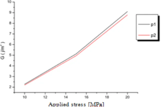
Fig. 4 represents the variation of the parameter GII as a
function of the stress applied for the two positions P1 and P2
on the delamination line.
For the weak constraints, one notices that there is not a big difference in the variation of the parameter GII (one notes only
a difference of 0.1 J/m2), which confirms that this last one is
almost constant along the width of the plate for a stress of 10 MPa.
Note also that the increase of the parameter GII is more
marked when the stress increases by 100%, therefore the rate of restitution of energy G increases by 95%. Note that the difference of the parameter GII between the two positions P1
and P2 is of the order of 0.5 J/m2.
Fig. 4 Evolution of G according to the stress applied for the two positions P1 and P2
P2
P1
World Academy of Science, Engineering and Technology International Journal of Aerospace and Mechanical Engineering
Vol:12, No:11, 2018
1044
International Scholarly and Scientific Research & Innovation 12(11) 2018 ISNI:0000000091950263
2. Delaminated Length of 65 mm
Fig. 5 represents the distribution of the energy release rate GII on the delamination line as a function of the stresses
applied, for a peel length of 65 mm.
It can be seen that the shape of the curve of the energy release rate GII is almost similar to that of the preceding
figure, but with the same amplitude of the applied stress, higher values of the parameter GII are noted. This explains
why the increase of the parameter G II is relative to the stress applied and to the delamination length.
According to the results obtained, the maximum stress applied must not exceed 15 MPa to remain in the elastic range of the composite material. The equivalent stresses of Von Mises developed depend on the type of loading and the geometry of the laminate.
Fig. 5 Distribution of G on the line delamination according to the loads, for a delamination of 65mm
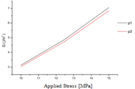
In Fig. 6, the evolution of the rate of energy restitution is shown as a function of the stresses applied for the two positions P1 and P2 with a delamination of 65 mm.
The same observations are observed as in the previous figure, a small difference in the parameter GII, between the
two positions for the small stresses applied, and a relatively high growth rate due to higher applied stresses. A difference between the constraints of 50% leads to an increase in the energy restitution rate higher than 100%. The difference of the parameter G between the two positions P1 and P2 is visible for
a stress of 15 MPa.
Fig. 6 Evolution of G according to the stress applied for the two positions P1 and P2
V. CONCLUSION
Three-dimensional finite element analysis (FEM) of the fracture behavior and stress field of laminated composites allows us to draw the following conclusions:
The delamination of the stratified composite material in mode II depends on the intensity of the applied load and the surface of the damaged area.
The values of the energy release rate are maximum at the two free ends of the laminated composite material, more precisely at the level of the delamination line, and they are minimum in the middle of the width of the plate.
The propagation of the delamination depends on the amplitude of the stress applied and the surface of the delamination zone.
In a composite plate subjected to bending, the delamination is favorable to appear in the free edges of the plate following the high level of the rate of energy restitution (geometric discontinuity).
REFERENCES
[1] Engrand D., A Boundary Layer Approach to the Calculation of Transverse Stresses along the Free Edges of a Symmetric Laminated Plate of Arbitrary Width under in Plane Loading, Composite Structures, (1981) 247-261.
[2] Dumontet H., Study of a Boundary Layer Problem in Elastic Composite Materials, M2AN, 20 (1986) 265-286.
[3] BAR-YOSEPH P., On the Accuracy of Interlaminar Stress Calculation in Laminated Plates, Comp. Meth. in Applied Mech. and Eng., 36 (1983) 309-329.
[4] O'Brien T. K., "Interlaminar fracture toughness: the long and winding road to standardization", Composite part B: Engineering, vol 29, pp. 57-62, 1998.
[5] Davies P., Sims G. D., Blackman B. R. K., Brunner A. J., Kageyama K., Hojo M., Tanaka K., Murri G., Rousseau C., Gieseke B. & Martin R. H., "comparison of test configurations for determination of mode II interlaminar fracture toughness results from international collaborative test programme", Plastics, rubber and composites, vol. 28, pp. 432-437, 1999.
[6] Williams J. G., "Fracture mechanics of anisotropic materials", dans: "Application of fracture mechanics to composite materials", Ed. par K. Friedrich, Amsterdam, Pay-Bas, Elsevier Science Publishers B. V., pp. 3-38, ISBN 0444872868, 1989.
[7] Gong X. J., "Rupture interlaminaire en mode mixte I+II du composite stratifié verre/époxy unidirectionnel et multidirectionnel", thèse: mécanique appliquée, acoustique, et matériaux. Compiègne: Université de technologie de Compiègne, N0 D 459, 1992.
[8] American society for testing and materials, "Standard test method for mode I interlaminar fracture toughness of unidirectional fiber-reinforced polymer matrix composite", Pennsylvanie, USA: ASTM International, N0 D 5528-94a, p 10, 1994.
[9] M. Kenane & M. L. Benzeggagh, mixed mode delamination fracture toughness of unidirectional Glass/Epoxy composites under fatigue loading.
[10] D. Benzerga, A. Haddi, A. Seddak, A. Lavie, A mixed-mode damage model for delamination growth applied to a new woven composite. Computational materials science 14(2008)515-525.
[11] J. Bonhomme, A. Argüelles, J. Viña, I. Viña, Numerical and experimental validation of computational models for mode I composite fracture failure, computational materials science (2009).
[12] Kim R. Y. & Soni S. R., Experimental and Analytical Studies on the Onset of Delamination in Laminated Composites, Journal of Composite Materials, 18 (1984) 70-76.
[13] Mathews, M. J. & Swanson, S. R. « Characterization of the interlaminar fracture toughness of a laminated carbon/epoxy composite. » Composites science and technology, 2007, vol. 67, p. 1489-1498. [14] Bent F. Sørensen, Torben K. Jacobsen, Characterizing delamination of
fibre composites by mixed mode cohesive laws, Composites Science and Technology 69 (2009) 445–456.
World Academy of Science, Engineering and Technology International Journal of Aerospace and Mechanical Engineering
Vol:12, No:11, 2018
1045
International Scholarly and Scientific Research & Innovation 12(11) 2018 ISNI:0000000091950263
[15] Blackman B. R. K., Brunner A. J. & Davies P., "Delamination fracture of continuous fibres composites: mixed-mode fracture", dans "Fracture mechanics testing methods for polymers, adhesives, and composites" Ed. Par D. R. Moore, A. Pavan & J. G. Williams, Oxford, Royaume-Uni, Elsevier Science Ltd, pp. 335-359, 2001.
[16] Brunner A. J., Blackman B. R. K. & Davies P., "Mode I delamination", dans: "Fracture mechanics testing methods for polymers, adhesives, and composites", Ed. par D. R. Moore, A. Pavan& J. G. Williams, Oxford, Royaume-Uni: Elsevier Science Ltd, pp. 277-305, 2001.
[17] Achache H., Madani Y. and Benzerdjeb A.; ”Effect of mechanical loading on the delamination of stratified composite in mode I”International Journal of Mechanical and Mechatronics Engineering, Vol. 10 N°2 (2016), 260-264.
[18] Product Dassault Systèmes Simulia Corp, ABAQUS Standard Version 6.10, Providence, RI, USA. 2010.
World Academy of Science, Engineering and Technology International Journal of Aerospace and Mechanical Engineering
Vol:12, No:11, 2018
1046
International Scholarly and Scientific Research & Innovation 12(11) 2018 ISNI:0000000091950263