3D optical imagery for motion
compensation in a limb ultrasound system
The MIT Faculty has made this article openly available.
Please share
how this access benefits you. Your story matters.
Citation
Ranger, Bryan J., et al. "3D Optical Imagery for Motion
Compensation in a Limb Ultrasound System." Proceedings Volume
9790, Medical Imaging 2016: Ultrasonic Imaging and Tomography,
27 February - 3 March, 2016,San Diego, California, edited by Neb
Duric and Brecht Heyde, 2016, p. 97900R. © 2016 SPIE.
As Published
http://dx.doi.org/10.1117/12.2218386
Publisher
SPIE
Version
Final published version
Citable link
http://hdl.handle.net/1721.1/114851
Terms of Use
Article is made available in accordance with the publisher's
policy and may be subject to US copyright law. Please refer to the
publisher's site for terms of use.
PROCEEDINGS OF SPIE
SPIEDigitalLibrary.org/conference-proceedings-of-spie3D optical imagery for motion
compensation in a limb ultrasound
system
Bryan J. Ranger, Micha Feigin, Xiang Zhang, Al Mireault,
Ramesh Raskar, et al.
Bryan J. Ranger, Micha Feigin, Xiang Zhang, Al Mireault, Ramesh Raskar,
Hugh M. Herr, Brian W. Anthony, "3D optical imagery for motion compensation
in a limb ultrasound system," Proc. SPIE 9790, Medical Imaging 2016:
Ultrasonic Imaging and Tomography, 97900R (1 April 2016); doi:
10.1117/12.2218386
_______________
*Corresponding author: branger@mit.edu; phone 1 617 715-4363; devicerealization.mit.edu | biomech.media.mit.edu
3D optical imagery for motion compensation in a limb
ultrasound system
Bryan J. Ranger
1,2,4,*, Micha Feigin
2,4, Xiang Zhang
3,4, Al Mireault
3,
Ramesh Raskar
2, Hugh M. Herr
1,2, Brian W. Anthony
3,41
Harvard-MIT Health Sciences and Technology Program, Massachusetts Institute of Technology and Harvard
Medical School, Cambridge, MA, USA 02139;
2Department of Media Arts and Sciences, Massachusetts
Institute of Technology, Cambridge, MA, USA 02139;
3Department of Mechanical Engineering,
Massachusetts Institute of Technology, Cambridge, MA, USA 02139;
4Institute for Medical Engineering and
Science, Massachusetts Institute of Technology, Cambridge, MA, USA 02139
ABSTRACT
Conventional processes for prosthetic socket fabrication are heavily subjective, often resulting in an interface to the human body that is neither comfortable nor completely functional. With nearly 100% of amputees reporting that they experience discomfort with the wearing of their prosthetic limb, designing an effective interface to the body can significantly affect quality of life and future health outcomes. Active research in medical imaging and biomechanical tissue modeling of residual limbs has led to significant advances in computer aided prosthetic socket design, demonstrating an interest in moving toward more quantifiable processes that are still patient-specific. In our work, medical ultrasonography is being pursued to acquire data that may quantify and improve the design process and fabrication of prosthetic sockets while greatly reducing cost compared to an MRI-based framework. This paper presents a prototype limb imaging system that uses a medical ultrasound probe, mounted to a mechanical positioning system and submerged in a water bath. The limb imaging is combined with three-dimensional optical imaging for motion compensation. Images are collected circumferentially around the limb and combined into cross-sectional axial image slices, resulting in a compound image that shows tissue distributions and anatomical boundaries similar to magnetic resonance imaging. In this paper we provide a progress update on our system development, along with preliminary results as we move toward full volumetric imaging of residual limbs for prosthetic socket design. This demonstrates a novel multi-modal approach to residual limb imaging.
Keywords: ultrasound, motion compensation, lower-extremity, limb imaging, prosthetics
1. INTRODUCTION
A critical component of a prosthesis is the socket, the cup-like interface that connects the prosthetic limb to an individual’s residual limb.1 Prosthetic socket design plays a pivotal role in ensuring user comfort, in avoiding tissue injury, and ultimately, in the quality of life of the prosthetic user.2 Despite this, creating an effective prosthetic socket remains a
significant challenge as it has been reported that nearly 100% of amputees experience discomfort as a result of wearing their prosthetic limb.3
Conventional fabrication processes for prosthetic socket fabrication are manual, not standardized, heavily subjective and often include very little quantitative patient-specific data.4 Thus, discrepancies exist between the quality of prosthetic
interfaces produced by different prosthetists. To address this, numerous areas of research have emerged that center on collecting quantitative information from a patient’s residual limb, and subsequently creating limb models to support computer-aided design and manufacturing (CAD/CAM) of sockets. This includes, but is not limited to, data collected from computed tomography (CT)5–7, magnetic resonance imaging (MRI)2,8, ultrasound (US)9–12, laser surface scanning13, and
Medical Imaging 2016: Ultrasonic Imaging and Tomography, edited by Neb Duric, Brecht Heyde, Proc. of SPIE Vol. 9790, 97900R · © 2016 SPIE · CCC code: 1605-7422/16/$18 · doi: 10.1117/12.2218386
mechanical indenters to gauge tissue stiffness.14,15 Despite these advancements, many of these tools are prohibitively
expensive, and are not always accessible to a broad patient population.
Recently, there has been increased demand for expanding the clinical applications of musculoskeletal (MSK) US, particularly for rehabilitative applications.16–18 In several ways, MSK US shows significant promise as a means to image and collect quantitative data of an individual’s limb (e.g., limb geometry and biomechanical tissue properties), and demonstrates distinct advantages as compared to X-rays, CT and MRI. More specifically, ultrasound imaging can be used in certain patients that are contraindicated for MRI imaging (e.g., are claustrophobic or obese), is portable, relatively low in cost compared to other imaging modalities, and lacks radiation risk.19
Multiple research groups have pursued volumetric ultrasound imaging of limbs with varying levels of success. Douglas et al.20 provide a thorough review of these technical efforts, portions of which are summarized here. Of particular relevance
are projects pursued by groups at Wright State University9–11 and Sandia National Labs12. Each group has independently
developed ultrasound B-mode systems that construct three-dimensional images of the residual limb. However, neither of the teams advanced to the point where their systems are used routinely in clinical practice. It turns out the mechanical setup of the scan was cumbersome, limb motion (which degrades image resolution) was difficult to compensate for, and final results did not allow for differentiation between tissue types.20
We are developing ultrasound limb imaging systems that address the design challenges highlighted by previous systems. Namely, designing a mechanical setup that allows for full lower-extremity imaging using a clinical ultrasound probe in a water tank, and creating image registration algorithms that robustly compensate for limb motion during scanning. In previously developed systems, motion compensation for image registration was completed exclusively through matching common image features. Feature matching has proven to be an ineffective approach, however, since shared anatomical structures may appear dissimilar in ultrasound images when collected at various probe orientations (e.g., the reflective surface of bone may appear different in neighboring images despite spatial overlap). Alternatively, we are pursuing a method that incorporates optical imagery to track limb motion during a scan.
In this paper, we present a progress update on our imaging system with preliminary results of our multi-modal imaging approach, using a conventional ultrasound probe and 3D optical imagery for motion compensation, for imaging of a human limb. Our first prototype demonstrated a multi-modal imaging approach that incorporated a clinical ultrasound probe, camera for motion tracking, and imaging tank.21 Using that method, we achieved compound ultrasound images that showed
similar anatomical distributions in the leg when compared to MRI; however, some motion artifact still remained. Building on the results from our previous study, we have iterated on the mechanical design of our setup to further automate the data acquisition process and update the optical tracking method. In terms of the motion tracking a 3D camera is now used to acquire a 3D surface as well as provide quantitative information about the location in space of the object being imaged during the scanning procedure. The iterative closest point algorithm (ICP)22 is used on the 3D camera data to define the
transformation due to motion between consecutive image acquisitions. This transformation is used to register and stitch the images together into a final compound image.
2. METHODS
2.1 Prototype Design
A side-view schematic of the system is shown in Figure 1A. A subject places his/her limb in the tank, and the ultrasound probe rotates circumferentially around the limb collecting images at set angular increments. A KinectTM One combination
3D, IR and color camera (Microsoft Corp., Seattle, WA) is positioned and secured below the tank looking upward to track three-dimensional limb and probe position during a scan, as well as collect a model of the limb surface. A top-view schematic depicting the coordinate frame for imaging is shown in Figure 1B, where θ defines the angular increment between ultrasound image acquisitions, and r defines the radial direction.
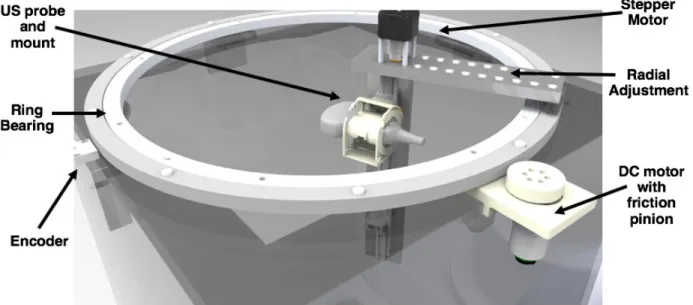
A CAD rendering that depicts the mechanical design of the ultrasound imaging system is shown in Figure 2. The prototype was constructed from a 24 inch3 clear acrylic tank, with a 600 mm-diameter ring bearing mounted to the top. A custom
3D-printed mount was fabricated to secure the ultrasound probe (Cephasonics Inc., Santa Clara, CA) to the rotating portion of the ring bearing; the mount is designed in such a way that allows the probe to be fixed at 0-, 45-, or 90-degree angles
Ultrasound probe I 3D Camera Registration markers 600 mm US probe and mount Ring Bearing Stepper Motor Radial Adjustment DC motor with
J
.
friction
pinion Encoderwith relation to horizontal. The flexibility of acquiring at multiple probe angles permits for different features to be accentuated depending on the orientation of the probe.
Figure 1: (A) Side-view schematic of the prototype ultrasound system. The ultrasound probe is mounted to a ring bearing
that allows for rotation circumferentially around the limb. A 3D camera is mounted below the tank, facing upward, and is used to track motion of the limb during scanning. (B) Top-view schematic showing the coordinate frame for imaging. The ultrasound probe rotates and collects images at set angular increments (θ) circumferentially around the limb. r represents the radial direction.
Figure 2: CAD rendering depicting the mechanical design of the ultrasound system. A ring bearing is mounted to the top of
a clear acrylic tank. An encoder tracks the position of the ring bearing in order to determine the θ-location of the probe. The ultrasound probe is mounted to the ring bearing so that it can rotate circumferentially around the limb. The system may be manually driven, but a stepper motor for vertical translation and DC motor with friction pinion for circumferential rotation are incorporated into the design for more automated data collection. Radial adjustment of the probe can be completed manually into set positions.
Circumferential rotation of the ring bearing can either be driven manually or by means of a DC motor with friction pinion (Pololu Electonics, Las Vegas, NV). A non-captive NEMA-17 stepper motor (Schneider Electric, Cambridge, MA) is incorporated into the design to enable automated vertical translation of the ultrasound probe. Additionally, the radial position of the ultrasound probe can be adjusted manually and locked into set positions; this enables scanning of a diverse range of limb sizes.
The circumferential position (θ) of the probe is tracked using a 1μm-resolution linear magnetic encoder system (Renishaw Incorporated, Gloucestershire, UK). The encoder consists of an adhesive-backed magnetic scale that was taped around the entire circumference of the ring bearing, and a non-contact encoder head to detect variations in the magnetic scale. The circumferential position (θ) of the probe is calculated using the detector’s output count value, and basic geometry.
2.2 Subject Recruitment
Following a procedure approved by the MIT Committee on the Use of Humans as Experimental Subjects (COUHES), both amputee and non-amputee subjects were recruited. Before the scan, the subject is required to complete a questionnaire that inquires about their health to ensure that they will be able to undergo the scan safely; this includes questions that ensure that the subject does not have any open wounds, inflammation, or history of chronic disease. In this paper, we present preliminary results of the arm of a subject, and the residual limb of an amputee subject.
2.3 Image Acquisition and Scan Procedures
MRI
MRI images are acquired to provide ground truth geometry of the limb for comparison to images generated using the experimental ultrasound prototype. The MRI images are obtained using a whole body 3T MRI scanner (Siemens Corp., Elrangen, Germany) with a flexible body/abdomen coil for transmission and receiving. The abdomen coil iss used instead of a knee coil to provide greater coverage of the limb volume. An ultra-short TE MRI (UTE-MRI) sequence was used
(TR/TE=5.8/0.1, acquisition matrix 256x256, 256 slices, voxel size 1.18x1.15x1.00 mm) for image data acquisition. The
subjects are placed in a prone position in the scanner. When scanning a leg, the subject’s thigh is propped up using foam pads so that the distal end of the limb is elevated off the scanning bed; this prevents areas of unwanted tissue compression. When scanning an arm, the subject is also placed in the prone position but with their arm extended above their head. Ultrasound Prototype
The imaging tank is filled with tap water that was approximately body temperature, and all efforts were made to ensure that the subject is comfortable during scanning. To complete the ultrasound scan, the subject is seated above the imaging tank and asked to submerge his/her limb into the water bath. The medical ultrasound transducer, since it is submerged in water, is encased in a sterile medical-grade watertight cover (CIVCO Medical Solutions, Kalona, IA). Once the subject is properly situated, the ultrasound probe completed a 360-degree pass circumferentially around the limb; during this period, the ultrasound probe and 3D camera collected data simultaneously. One 360-degree pass takes on the order of 1-2 minutes to complete. To acquire an image of the limb where the tissue is not deformed, the imaged portion of the limb is not physically constrained; therefore, motion of the limb was due solely to natural movement of the subject.
2.4 Motion Compensation with 3D Optical Imagery
The KinectTM camera provides a depth images (point cloud) along with an IR and RGB (color) image. As water highly
attenuates IR illumination (used for both the depth image as well as the IR image), areas with no object in them are very noisy. Initial processing includes creating an error measure for each pixel in the image based on the local standard deviation of gray scale values. This allows to filter out areas with no object. The image is then segmented based on depth, location and object size to find both the leg and the probe. The 3D point cloud for the leg is further filtered for noise using the moving least squares method.
The iterative closest point algorithm (ICP)22 was used on the 3D point clouds of the leg to define the transformation due
to motion between consecutive image acquisitions. This transformation is used to register and stitch the images together into a final compound axial image slice (motion compensation).
50 100 159 200 259 300 350 CN 050 500 50 100 150 200 250 300 350 400 50 ,W ,59 IN 350 300 350 400 450 500 50 100 150 200 250 300 350 400
0001 006 002 COL 009 OUP WV WE CO? OM
0021 0091 0011 0001 0001 ace 009 roe CO?
The procedure to achieve this was to first rotate collected images to the angle (θ) that they were acquired at and place each at an initial radius (r) in the compound image space. The position of each image is then adjusted using the transformation output by the ICP algorithm. For overlapping spatial regions of the images, the maximum value pixel was chosen as the pixel value for the compound image slice.
Using the approximate probe location gathered from the depth image, we also find the probe location and orientation in the IR image. This is done using a sum of square difference (SSD) comparison with a template image. As the IR image is captured using active illumination as well as due to the attenuation of IR illumination in water, background clutter is eliminated and illumination is constant, making SSD an ideal choice.
3. RESULTS
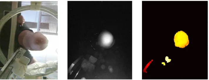
A set of example results from the KinectTM 3D camera, which is placed below the imaging tank, is shown in Figure 3. The
left represents a color image showing the camera view in the imaging tank. The center shows the IR image (on a log scale) depicting separation of the background compared to the color image shown on the left. To the right is the depth image, which has been filtered to remove noise in order to only show leg, probe and rail supporting the probe.
Figure 3: Example set of results from the KinectTM camera of our system of a lower-extremity amputee subject. Left: Color
image showing camera view. Center: IR image (log scale) showing separation of the background compared to the color image. Right: The depth image, which has been filtered based on noise levels to only show leg, probe and rail supporting the probe. Red represents a depth that is close to the camera, while white represents further distances.
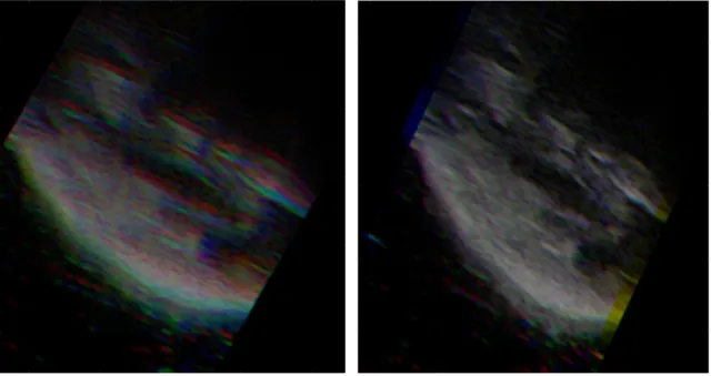
Figure 4 shows an example result of our motion compensation framework on a few individual images. Here, three neighboring image frames are shown without (Figure 4A) and with (Figure 4B) motion compensation. In the figure, each color channel represents a different frame.
Figure 4: Result using our motion compensation framework. Image frames are designated by different color channels. (A)
Before motion compensation. (B) After motion compensation.
For this paper, we present preliminary results of a human residual limb and a human arm. The arm scan, which was acquired when a subject submerged their arm into the water tank and held their hand in a fist, provides a similar data set to a suspended residual limb in the tank (a scan of a leg of a non-amputee proved difficult in this particular study since the subject’s foot would block a large portion of the field of view of the 3D camera). The resulting compound ultrasound image slice of a subject’s arm can be seen in Figure 5, with an MRI scan of the same arm. It is important to note that the MRI and US images may not be the exact same axial slice in the arm since registration markers were not used.
Figure 5: Left: UTE-MRI image of a subject’s arm. Acquisition parameters: TR/TE=5.8/0.1, matrix 256x256, 256 slices,
voxel size 1.18x1.15x1.00 mm. Right: Resulting ultrasound image slice of the same limb from our prototype system.
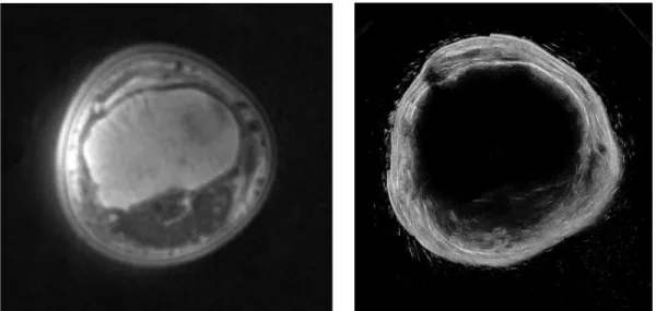
Similarly, a preliminary result from our ultrasound system of a residual limb can be seen in Figure 6, with a corresponding MRI of the same subject. Again, it is important to note that images may not be the exact same axial slice in the residual limb since registration markers were not used.
Figure 6: Left: UTE-MRI image of a subject’s residual limb. Acquisition parameters: TR/TE=5.8/0.1, matrix 256x256,
256 slices, voxel size 1.18x1.15x1.00 mm. Right: Resulting ultrasound image slice of the same limb from our prototype system.
4. DISCUSSION
We present a progress update on our ultrasound limb imaging system with some preliminary results. We first showed the design of the imaging tank, and subsequently introduce a motion compensation framework, using 3D camera imagery, to counteract limb motion during scanning. Finally, we showed initial results of creating a single compound axial image slice of a human residual limb and arm. These results represent steps toward full volume limb imaging for the clinical application to prosthetic socket design.
Figure 3 depicts an example set of results from the KinectTM 3D camera, specifically for an amputee subject’s residual
limb. These data are collected simultaneously with ultrasound image capture, and are used to track both limb and probe motion during the scan. A few neighboring frames are shown before and after motion compensation in Figure 4. When looking at the image on the left, a blurring effect is created due to patient motion. The right figure shows the result of how individual images are shifted in the compound image using optical tracking from the 3D camera depth image.
The arm scan, shown in Figure 5, and residual limb scan, shown in Figure 6, show similar anatomical structures and overall limb geometry as compared to their respective MRI’s. The UTE-MRI was chosen as the ground truth for comparison since it has been optimized to delineate bone boundaries from soft tissue.
This paper represents a proof-of-concept pilot study; therefore, several limitations are noted. First, we present a very limited data set of n=1 arm and n=1 residual limb. In future studies, a larger cohort of patients will be reviewed, along with their respective MRI, for further validation. Moreover, as noted in the results, the MRI slice did not necessarily correlate precisely with the axial slice created using ultrasound. In future studies, MR surface fiducial markers (Beekley Medical, Bristol, CT) that are also visible in ultrasound, will be utilized to ensure a direct comparison between the two imaging modalities. Furthermore, our ultrasound probe used default parameter settings when acquiring data. Because of this, penetration depth, focus, and resolution of the output were not optimized for our water tank setup, resulting in images that did not provide adequate depth. In future scans, we will optimize ultrasound imaging parameters of our probe so that we achieve better depth resolution.
Though preliminary, the results of this paper show the feasibility of using 3D optical data as a means of tracking motion of an imaged body and a clinical ultrasound probe in a water tank, and have warranted future work. In the near term, iterations on the mechanical design of the imaging tank will be completed to allow for volumetric scanning of the entire limb; this includes a more automated acquisition scheme to decrease scan time. With respect to image processing, more advanced registration algorithms to compensate for limb motion in three dimensions, as well as edge detection to create 3D surfaces of skin and bone will be developed.
In a broader sense, this work represents steps toward collecting free-hand ultrasound images of the limb and subsequently stitching them together into an image volume. Upon further development of motion tracking of the probe and limb in three-dimensional space, the ultrasound probe will be decoupled from the mechanical positioning system so that images can be collected free hand. Such a tool would provide clinicians with a means of collecting quantitative data of human limbs for prosthetic socket design by allowing for the creation of 3D CAD surface models of limb geometry as well as biomechanical tissue models based on limb anatomy and elastic properties. Furthermore, such research has many additional clinical applications including imaging of muscular dystrophy and bone density monitoring, as well as ultrasound computed tomography systems that would be improved upon with motion compensation.
5. CONCLUSION
In summary, we present a progress update and show preliminary results as we move toward full volumetric ultrasound imaging of residual limbs for prosthetic socket design. Utilizing ultrasound images collected from a conventional probe, along with data acquired from a 3D camera to compensate for limb and probe motion, demonstrates a novel multi-modal approach to residual limb imaging.
6. ACKNOWLEDGMENTS
This work was supported in part by the National Science Graduate Research Fellowship Program. The authors wish to thank David Sengeh and Arthur Petron of the Biomechatronics Group at the MIT Media Lab, and Jonathan Fincke of the Device Realization Lab at MIT for their help and guidance. We also wish to thank the Martinos Imaging Center at the MIT McGovern Institute for their assistance with acquiring MRI data.
REFERENCES
[1] Laing, S., Lee, P. V.., Goh, J. C., “Engineering a trans-tibial prosthetic socket for the lower limb amputee.,” Ann. Acad. Med. Singapore 40(5), 252–259 (2011).
[2] Lee, V. S. P., Solomonidis, S. E.., Spence, W. D., “Stump-socket interface pressure as an aid to socket design in prostheses for trans-femoral amputees--a preliminary study,” Proc. Inst. Mech. Eng. Part H J. Eng. Med. 211(2), 167–180 (1997).
[3] Nielson, C. C., “A Survey of Amputees: Functional Level and Life Satisfaction, Information Needs, and the Prosthetist’s Role,” J. Prosthetics Orthot. 3(3), 125–129 (1991).
[4] Zheng, Y. P., Mak, a F.., Leung, a K., “State-of-the-art methods for geometric and biomechanical assessments of residual limbs: a review.,” J. Rehabil. Res. Dev. 38(5), 487–504 (2001).
[5] Vannier, M. W., Commean, P. K., Brunsden, B. S.., Smith, K. E., “Visualization of Prosthesis Fit in Lower-Limb Amputees,” Simul. Model. 17(5), 16–29 (1997).
[6] Faulkner, V. W.., Walsh, N. E., “Computer Designed Prosthetic Socket from Analysis of Computed Tomography Data,” J. Prosthetics Orthot. 1(3), 154–164 (1989).
[7] Smith, K. E., Commean, P. K.., Vannier, M. W., “Residual-limb shape change: three-dimensional CT scan measurement and depiction in vivo,” Radiology 200, 843–850 (1996).
[8] Todd, B. A.., Wang, H., “A visual basic program to pre-process MRI data for finite element modeling,” Comput. Biol. Med. 26(6), 489–495 (1996).
[9] He, P., Xue, K., Fan, Y.., Wang, Y., “Test of a vertical scan mode in 3 - D imaging of residual limbs using ultrasound,” 36(2), 1–11 (1999).
[10] He, P., Xue, K., Chen, Q., Murka, P.., Schall, S., “A PC-Based Ultrasonic Data Acquisition System for Computer-Aided Prosthetic Socket Design,” 4(2), 114–119 (1996).
[11] Zheng, J., He, P., Xue, K.., Jin, C., “Image fusion in 3D ultrasound scan of residual limbs,” Proc. First Jt. BMES/EMBS Conf. 1999 IEEE Eng. Med. Biol. 21st Annu. Conf. 1999 Annu. Fall Meet. Biomed. Eng. Soc. (Cat. No.99CH37015) 2, 1061, IEEE (1999).
[12] Morimoto, A. K., Bow, W. J., Strong, D. S., Dickey, F. M., Krumm, J. C., Vick, D. D., Kozlowski, D. M., Partridge, S., Warsh, N., et al., “3D Ultrasound Imaging for Prosthesis Fabrication and Diagnostic Imaging,” Sandia Natl. Labs (1995).
[13] Houston, V. L., Mason, C. P., Beattie, A. C., LaBlanc, K. P., Garbarini, M., Lorenze, E. J.., Thongpop, C. M., “The VA-Cyberware lower limb prosthetics-orthotics optical laser digitizer.,” J. Rehabil. Res. Dev. 32(1), 55–73 (1995).
[14] Zheng, Y., Mak, a F.., Lue, B., “Objective assessment of limb tissue elasticity: development of a manual indentation procedure.,” J. Rehabil. Res. Dev. 36(2), 71–85 (1999).
[15] Ahn, B.., Kim, J., “Measurement and characterization of soft tissue behavior with surface deformation and force response under large deformations.,” Med. Image Anal. 14(2), 138–148, Elsevier B.V. (2010).
[16] Hall, M. M., “Musculoskeletal Ultrasound in Physical Medicine and Rehabilitation,” 38–47 (2013).
[17] Ozçakar, L., Carli, A. B., Tok, F., Tekin, L., Akkaya, N.., Kara, M., “The utility of musculoskeletal ultrasound in rehabilitation settings.,” Am. J. Phys. Med. Rehabil. 92(9), 805–817 (2013).
[18] Nutz, D. J., “A Musculoskeletal Ultrasound Course for Physical Medicine and Rehabilitation Residents,” 56–69 (2010).
[19] Wu, C., Chen, W., Park, G., Wang, T.., Lew, H. L., “Musculoskeletal Sonoelastography : A Focused Review of its Diagnostic Applications for Evaluating Tendons and Fascia,” J. Med. Ultrasound 20(2), 79–86, Elsevier Taiwan LLC and the (2012).
[20] Douglas, T., Solomonidis, S., Sandham, W.., Spence, W., “Ultrasound imaging in lower limb prosthetics.,” IEEE Trans. Neural Syst. Rehabil. Eng. 10(1), 11–21 (2002).
[21] Ranger, B. J., Feigin, M., Pestrov, N., Zhang, X., Lempitsky, V., Herr, H. M.., Anthony, B. W., “Motion compensation in a tomographic ultrasound imaging system: Toward volumetric scans of a limb for prosthetic socket design,” Proc. Annu. Int. Conf. IEEE Eng. Med. Biol. Soc. EMBS, 7204–7207 (2015).
[22] Besl, P.., McKay, N., “A Method for Registration of 3-D Shapes,” IEEE Trans. Pattern Anal. Mach. Intell. 14(2), 239–256 (1992).