HAL Id: hal-00984184
https://hal.archives-ouvertes.fr/hal-00984184
Submitted on 28 Apr 2014HAL is a multi-disciplinary open access archive for the deposit and dissemination of sci-entific research documents, whether they are pub-lished or not. The documents may come from teaching and research institutions in France or abroad, or from public or private research centers.
L’archive ouverte pluridisciplinaire HAL, est destinée au dépôt et à la diffusion de documents scientifiques de niveau recherche, publiés ou non, émanant des établissements d’enseignement et de recherche français ou étrangers, des laboratoires publics ou privés.
Influence of the inductor shape, and the magnetization
processes on a trapped magnetic flux in a
superconducting bulk
Bashar Gony, Rafael-Antonio Linares-Lamus, Qunxu Lin, Kévin Berger,
Bruno Douine, Jean Lévêque
To cite this version:
Bashar Gony, Rafael-Antonio Linares-Lamus, Qunxu Lin, Kévin Berger, Bruno Douine, et al.. In-fluence of the inductor shape, and the magnetization processes on a trapped magnetic flux in a superconducting bulk. Physica C: Superconductivity and its Applications, Elsevier, 2014, 503, pp.S0921453414001440. �10.1016/j.physc.2014.04.036�. �hal-00984184�
Influence of the inductor shape, and the magnetization
processes on a trapped magnetic flux in a superconducting
bulk
B GONY, R LINARES, Q LIN, K BERGER, B DOUINE, and J LEVEQUE
GREEN - Université de Lorraine, Faculté des Sciences et Technologies, Vandœuvre-lès-Nancy, France
E-mail: bashar.gony@univ-lorraine.fr
Abstract. In this paper, we study the form of the inductor for producing a magnetic field in a
superconductor bulk by using a method of PFM (Pulsed Field Magnetization). We tested two inductors: vortex coil and systeme of three coils, where we found the best results with the systeme of three coils. After that, we presente two processes for trapping a magnetic field in the bulk: direct magnetization and successive magnetization where we found similar results.
1. Introduction
High-temperature superconductors are a new kind of superconductors which are promising materials for the permanent magnet applications [1-5]. Single domain bulk melt-processed RE–Ba–Cu–O has a large potential for use in permanent-magnet like engineering applications, such as magnetic bearings [6, 7], and high power density rotating machines [8-12] because it can trap a high value of magnetic fields [13, 14]. This kind of superconductor bulk can also shield the magnetic field and concentrate the flux to obtain a large density of magnetic field in some applications [15].
Until now, the maximum value of remnant magnetic induction in a permanent magnet is about 1.5 Tesla for NdFeB. But by using the principle of trapping the magnetic field by eddy currents in a High critical Temperature Superconductor (HTS), it is possible to obtain 4 T on the surface of a superconducting bulk at 77 K (liquid nitrogen) and 17 T at 29 K [13].
In general, there is an interest to increase the value of the induction. For example, an application that aims to transfer an effort, increase the value of the induction to increase the value of the magnetic energy in the gap and thus the electromagnetic torque. Our aim is to optimize the magnetization of the superconducting bulk and its processes.
There are several methods of magnetization but we chose the most convenient method to implement in situ, it is PFM "Pulsed Field Magnetization" method. The general principle of this method is to discharge a capacitor in a coil which we call the inductor. This discharge will generate a magnetic field pulse which will induce currents and trapping a magnetic field in the superconductor bulk. This value of trapped magnetic field in the bulk depends on [16- 18]: The critical current density Jc in the bulk, the size of the bulk, and the form of the magnetic field pulse applied on the bulk.
In the literature, the PFM method was carried out by using only one coil, a long cylinder, around the superconducting bulk [19, 20]. Some authors magnetize the bulk by using two coils one above it and the second below it [21, 22, 23]. In this paper, we study a small vortex coil above the bulk which is useful for the application where we don’t have a large space to do the magnetization and only one magnetized surface of the bulk is needed. We study also a system of three coils that is useful for the electrical applications where we have enough space (e.g. magnetic coupling, and axial motors applications) and the need for a large value of trapped magnetic field on the two surfaces of the bulk. For both systems, the vortex coil and the two coils, above and below the bulk, in the system of three coils can be removed after the magnetization.
First, we present the experimental devices which we used for doing the magnetization and obtained the profile of magnetic field after the magnetization. We show also the operating mode to obtain the
optimal magnetic field in the superconductor bulk. Then the study of two types of inductors used and comparison of different methods of magnetization are exposed.
2. EXPERIMENTATION 2.1 Experimental means
In this section, we present the superconducting bulk, the two types of inductors, the circuit of magnetization, and the measurement of the trapped magnetic field profile. The work was carried out at a constant temperature of 77 K, the temperature of liquid nitrogen.
2.1.1. Superconducting bulk
We carried out all measurements on a superconducting bulk of YBCO that has the dimensions 16 mm diameter, and 8 mm of height. The critical temperature of this bulk is 92 K. This superconducting bulk has some holes parallel with the Z axe. The diameter of every hole in the bulk is about 0.5 mm with a high of 8 mm [24]. These holes maximize the trapped magnetic field by enhancing the oxygen annealing and the heat exchange with the cooling liquid [25]. Figure 1.
Figure 1. Superconducting bulk.
For measuring the magnetization of the bulk, the magnetic field at the center of the bulk surface is measured by a Hall sensor adapted to low temperatures. The distance between the active part of the sensor and the surface of the bulk is about 0.5 mm.
2.1.2 Inductors
In this domain of magnetization, many types of inductor were tested. For knowing the difference between some shapes of inductor, we test and compare two types (a vortex type, and a system of three coils). We choose this kind of copper coils in order to produce the highest possible value of magnetic field, but we have some limit conditions:
• The maximum of discharge current in the RLC circuit is limited to the thyristor peak current limit, 8000 A. This peak current limits the possible values of R and L of the designed coil. • In order to maximize coupling between the coils and the bulk, the coils are chosen as close as
possible to the bulk, according to the dimension of the superconducting bulk and also to the cooling capacities.
a) The vortex coil
For magnetizing the bulk, we use a copper coil as an inductor with the following parameters:
Table 1. Characteristic of the vortex coil
Number of turns Effective height (mm) Effective diameter (mm) Inductance (��) 8 3.7 41 ∼ 4
To hold the coil, it has been molded with the resin. Figure 2 shows the coil and its position relative to the bulk.
Figure 2. Magnetization with a vortex coil.
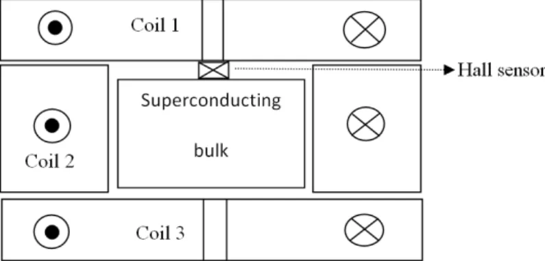
b) The system of three coils
We will use another inductor which consists of three copper coils, the first coil is above the bulk, the second coil is around it, and the third coil is below it. The three coils are connected in series and the field seen by the bulk is created by the sum of the three coils which have the following field settings:
Table 2. Characteristic of the system of three coils
Number of turns Effective height (mm) Effective diameter (mm) External diameter (mm) Internal diameter (mm) Inductance (��) Coil 1, and 3 Coil 2 40 32 20 11.4 52 - - 52 - 16.5 ∼ 30 ∼ 20
Figure 4 shows the system of 3 inductors with the superconducting bulk.
Figure 3. System of three coils around the superconducting bulk. 2.1.3 Circuit magnetization and operating mode
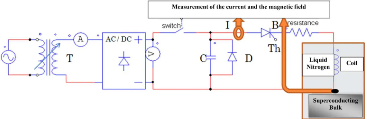
To magnetize a superconducting bulk we use an electrical circuit (figure 4) which consists mainly of a variable transformer 0-350 V, a rectifier AC /DC, 24 capacitors in parallel (total capacity 80 mF), a thyristor can support a maximum current of 8000 A, a diode D, a coil (or inductor), and some measuring devices (oscilloscope, voltmeter and ammeter).
The optimal magnetic field is defined as the minimum value of the peak of magnetic field pulse applied to the superconducting cold bulk to magnetize it with a maximum trapped field. We can also define the pulse related to this field as the optimal pulse. To find the optimal pulse with the experiments, we chose the following operating mode, which consists of five steps:
1 Fix an initial value of the AC output voltage Ut of the variable transformer.
2 Close the switch to charge the capacitor with a DC voltage through the rectifier AC / DC. Note: the thyristor Th is still open in this section.
3 Open the switch after charging the capacitor C.
4 Close the thyristor Th by applying a pulse to its gate. That it produces a current pulse flows in the electrical circuit associated to a pulse of the magnetic field on the bulk.
Figure 4. Electrical circuit.
If this field is high enough to penetrate into the bulk, it will remain a trapped magnetic field into the bulk. We measure and save the magnetic field pulse, the trapped field and the current in the electrical circuit by using the oscilloscope.
5 Repeat the previous four steps by increasing the transformer voltage Ut, until arriving at the optimal magnetic field.
Note: Apply the optimal pulse 2-3 times enhance slightly the trapped magnetic field. 2.1.4 Measurement of the trapped magnetic field profile
After magnetization, and to know the distribution of trapped magnetic field on the surface of the superconducting bulk, we put the bulk on an XYZ table (Figure 5) that allows us to make a matrix of values of the magnetic field in a plane parallel to X0Y with a distance Z = 0.5 mm from the surface of the bulk. We chose one measuring step X = Y = 2.22 mm. Unfortunately for this measurement of magnetic field profile we must remove rapidly the superconducting bulk from the inductor and move it to the XYZ table. The bulk is caught inside the inductor whit a fixation system. So, this movement is in the free air at the room temperature so the magnetization of the bulk decreases slightly during this operation. This is even more critical in the case of three coils system because the extraction of the bulk from the three coils takes more time than in the case of the vortex coil.
Figure 5. Measurement of the magnetic field profile after the magnetization on 20 �� × 20 �� area.
2.2 The different processes of magnetization
We study two process of magnetization and we have compared the results. 2.2.1 Direct magnetization process
In this process (figure 6), two pulses are applied to an initial voltage level and we store the maximum of magnetic field applied on the bulk and the trapped magnetic field in the bulk after 30 minutes of the end of the second magnetic field pulse. Then we cancel the trapped magnetic field by heating the bulk. This process is repeated by increasing the voltage of the capacitor (i.e the applied field) until we find the optimal magnetic field. In other words the bulk is free of any magnetic field whenever the magnetization is carried out at a higher magnetic field pulse.
Figure 6. Direct Process of magnetization. 2.2.2 The process of successive magnetization
In this process (figure 7), we also apply two pulses to a selected voltage level, but we will not cancel the trapped magnetic between two different voltage levels. That is mean, the bulk is already magnetized when a new pulse is carried out (the bulk is kept in liquid nitrogen). We measure the trapped magnetic field 1 min after the end of the second pulse but when we arrive at the optimal field we measure the trapped magnetic field after 30 min of the pulse end.
Figure 7. Successive process of magnetization.
In the two processes, the maximum value of the applied field and trapped field in the bulk are saved.
3. RESULTS AND DISCUSSION
3.1 Study of the influence of the inductor shape
For the vortex coil, the second optimal pulse measured by the Hall sensor and the current pulse in the circuit of magnetization are shown in figure 8. It contains the following information:
Table 3. Magnetization pulse with vortex coil. Current
max (A)
Pulse duration (ms)
Optimal field (T) (with the reaction
of the bulk)
Trapped magnetic field at the end of
the pulse (T)
Trapped magnetic field after 30 min of the pulse
end (T)
6000 2.7 1.24 0.25 0.2
Figure 8. Optimal field Pulse and its current in the inductor.
The figure 9 shows the profile of the magnetic field measured by using the XYZ table for the two surfaces of the bulk after 30 minutes at the end of the magnetization cycle. For the face which is in front of the vortex coil, we find that the maximum value of the trapped field is 0.2 Tesla. This field is in the centre of the bulk face, figure 9 (a). For the other face, the bulk has low values of trapped magnetic field; we find the minimum values at the edge of the bulk and also at the center, figure 9(b).
-2 0 2 4 6 8 x 10⁻³ 0 0.2 0.4 0.6 0.8 1 1.2 1.4 Time (Sec) Magnetic field (T) -2 0 2 4 6 8 x 10⁻³ 0 1000 2000 3000 4000 5000 6000 7000 Current (A)
Magnetic field pulse
Current pulse
Trapped magentic field in the bulk at the end of the pulse
Figure 9(a). Magnetic field profile on the bulk at z=0.5mm, 30 minutes after the magnetization by the vortex coil. In front of the vortex coil.
Figure 9(b). Magnetic field profile on the bulk at z=0.5mm, 30 minutes after the magnetization by the vortex coil. On the opposite face to the vortex coil.
This distribution of the magnetic in the first face of the bulk is due to the easy and direct penetration (the coil is directly in front of the bulk surface), which is not the case for the other face.
For the system of three coils, figure 10 shows the second optimal pulse of field measured by the Hall probe and the current pulse in the circuit of magnetization. From this experiment, we find the following information:
Table 4. Magnetization pulse with 3 coils system Current max
(A)
Pulse duration (ms)
Optimal field (T) (with the reaction
of the bulk)
Trapped magnetic field at the end of
the pulse (T)
Trapped magnetic field after 30 min of the pulse end (T)
1034 20 1.34 0.7 0.45
Figure 10. Optimal field pulse and its current in the inductor. -10 -5 0 5 10 -10 -5 0 5 10 -0.1 0 0.1 0.2 0.3 Axis X (mm) Axis Y (mm) Magnetic field (T) 0 0.02 0.04 0.06 0.08 0.1 0.12 0.14 0.16 0.18 0.2
Maximum magnetic field = 0.2 T
-10 -5 0 5 10 -10 -5 0 5 10 -0.02 0 0.02 0.04 0.06 0.08 Magnetic field (T) 0 0.01 0.02 0.03 0.04 0.05 0.06 0.07 Maximum magnetic field = 0.07 T
-0.01 -0.005 0 0.005 0.01 0.015 0.02 0.025 0 0.2 0.4 0.6 0.8 1 1.2 1.4 Magnetic field (T) -0.01 -0.005 0 0.005 0.01 0.015 0.02 0.025-200 0 200 400 600 800 1000 1200 Time (Sec) Current (A) Magnetic field pulse Current pulse
Trapped magnetic Field at the end of the pulse
The trapped magnetic field is comparable to the one measured at the surface of a permanent magnet placed in the air e.g. NdFeB with a remanent induction of 1.2 T. Figure 11 shows the field profile for the two faces of the bulk measured one hour after the end of the cycle of magnetization (= 30 min in the inductor + 30 min to liberate the bulk and install it on the XYZ table). We observe that the maximum value of trapped field is 0.36 T less than the measured value 0.45 T due to technical problems related to the measurement of the field profile presented in section 2.1.4.
Figure 11. The profile of the magnetic field after the magnetization (the same for the bulk faces top and bottom).
By comparing the two trapped fields in the bulk by using two types of inductors, we found that it is more interesting to use the system of three coils for two raisons:
1- The trapped magnetic field is stronger.
2- The magnetization is the same for the two faces of the bulk.
But the implementation and installation of the experiments with this system is more difficult than the simple vortex coil.
One question is remained, why we have different trapped magnetic fields in the same superconducting bulk when we use different inductors?
If we compare the two optimal pulses of magnetization (figure 8, and Figure 10), we find that we have almost the same maximum value of magnetic field pulse, but we have different pulse duration, in the system of three coils the pulse duration is 10 times more than pulse duration in the vortex coil, due to L, and R of the inductor.
The forces during the magnetization cycle have three principal sources: FL Lorentz force density
FP Pinning force density FV Viscous force density
During the PFM operation, the flux motion depends on the following force balance [19]: FL + FP + FV = 0
Where FV depends on the flux velocity � :
FV =−� |�| �0 �
Where � is the viscosity coefficient, and �0 is a fluxoid quantum.
The presence of a large viscous force must be responsible for the formation of an apparent barrier. The variation of the magnetic field during the PFM operation for the vortex coil is 6-7 times more than its variation in the case of the system of three coils. So we have a large viscous force during the magnetization by using the vortex coil compared with the system of three coils.
-10 -5 0 5 10 -10 -5 0 5 10 -0.1 0 0.1 0.2 0.3 0.4 Axis X (mm) Axis Y (mm) Magnetic field (T) 0 0.05 0.1 0.15 0.2 0.25 0.3 0.35
It’s also the reason that we obtain better results with the ZF, and ZFC method (Field Cooling, and Zero Field Cooling) where the viscous force is negligible and the variation of magnetic field is very slow and its value close to zero.
3.2 Study of different processes of magnetization
We will use the system of three coils for the two process of magnetization due to the last results. Figure 12 shows the evolution of the trapped field in the bulk according to the maximum applied field using the direct magnetization process. We found that the maximum trapped field is 0.47 T with a maximum applied field of 1.34 T and for larger values of the applied field the bulk will saturate.
Figure 12. Trapped field according to the maximum applied field.
Figure 13 shows the evolution of the trapped field in the bulk according to the maximum applied field by using the successive magnetization process. We find that the maximum trapped field of 0.45 T with a maximum applied field of 1.34 T.
Figure 13. Trapped field according to the maximum applied field.
By comparing the results of the two methods of magnetization, we did not find significant differences. So we propose to use the simplest process. If we already know the optimal field for the bulk, the direct magnetization process is advised to apply.
0 0.2 0.4 0.6 0.8 1 1.2 1.4 1.6 0 0.05 0.1 0.15 0.2 0.25 0.3 0.35 0.4 0.45 0.5
Maximum applied field (T)
Tra
ppe
d magnetic
field in the bulk
(T) 0 0.2 0.4 0.6 0.8 1 1.2 1.4 1.6 0 0.05 0.1 0.15 0.2 0.25 0.3 0.35 0.4 0.45 0.5
maximum applied field (T)
Tra
ppe
d magne
tic
4. CONCLUSION
Through our experimental results and simulations, we have shown clearly the benefit of the three coils system in series. We also presented the results from the analysis of two magnetization processes used. In the future works, we hope to enhance the trapped magnetic field in the bulk by using a pulse control system which can increase the time duration of the magnetization pulse. Finally, these works on the magnetization by PFM in liquid nitrogen allow us to discuss the technological choices to consider for magnetize one superconducting bulk or more in a motor application type, or coupling magnetic operated in a lower temperature.
References
[1] Campbell A M and Cardwell D A 1997 Cryogenics 37 567-575
[2] Yamachi N, Nishikawa T, Tomita M, Sawa K and Murakami 2002 Physica C 378 877-882 [3] Sander M 2005 IEEE Trans. Appl. Supercond. 15 1431–1434
[4] Habisreuther T H, Litzkendorf D, Surzehenko O, Zeisberger M, Muller R, Riches J, Scauroth S, Dellith J and Gawalek W 2001 IEEE Trans. Appl. Supercond. 11 3501–3504
[5] Vanderbemden P, Hong Z, Coombs T A, Ausloos M, Hari Babu N, Cardwell D A and Campbell A M 2007 Supercond. Sci. Technol. 75 174515
[6] Coombs T A Campbell A M Storey R and Weller R 1999 IEEE Trans. Appl. Supercond. 9968-971 [7] Mulcahy T M Hull J R Uherka K L Abboud R G and Juna J J 2001 IEEE Trans. Appl. Supercond. 111729-1732
[8] McCulloch M D and Dew-Hughes D 1998 Materials Science and Engineering: B 53 211-215 [9] Oswald B Best K J Setzer M Soll M Gawalek W Gutt A Kovalev L Krabbes G Fisher L and Freyhardt H C 2005 Supercond. Sci. Technol 18 S24
[10] Alvarez A Suarez P Caceres D Granados X Obradors X Bosch R Cordero E Perez B Caballero A Blanco J A 2002 Physica C 372–376, Part 3 1517-1519
[11] Qiu M, Huo H K, Xu Z, Xia D, Lin L Z and Zhang G M 2005 IEEE Trans. Appl. Supercond. 15 3172 – 3175
[12] Stumberger G Aydemir M T Zarko D Lipo T A 2004 IEEE Trans. Appl. Supercond. 14 54–62 [13] Tomita M and Murakami M 2003 Nature 421 517-520
[14] Eisterer M Haindl S Zehetmayer M Gonzalez-Arrabal R Weber H W Litzkendorf D Zeisberger M Habisreuther T Gawalek W Shlyk L Krabbes G 2006 Supercond. Sci. Technol. 19 S530
[15] Ailam E Netter D Lévêque J Douine B Masson P J Rezzoug A 2007 IEEE Trans. Appl. Supercond. 17 27-33
[16] Chen L Cha Y S H Claus H Zheng H Veal B W and PengF Z 2006 IEEE Transactions on Plasma Science 34 1702-1708
[17] K. Berger « Etude des phénomènes couplés magnétothermiques dans les Supraconducteurs à Haute Température », http://tel.archives-ouvertes.fr/tel-00348299, Thèse de doctorat, Université Henri Poincaré - Nancy 1, 2006.
[18] Douine B Sirois F Leveque J Berger K Bonnard C Hoang T Mezani S 2012 IEEE Trans. Appl. Supercond 22 9001604-9001604
[25] Lousberg Gregory P Ausloos M Vanderbemden Ph and B Vanderheyden B 2008 Supercond. Sci. Technol. 21 025010
[19] Mizutani U Oka T Itoh Y Yanagiy Y Yoshikawa M and Ikuta H 1998 Applied Superconductivity 6 235-246
[20] Lihua Chen Yung S. Cha Helmut Claus Hong Zheng Boyd W. Veal and Fang Z. Peng 2006 IEEE Transactions on Plasma Science 34 5
[21] Hiroyuki Ohsaki Tatsuya Shimosaki and Naoyuki Nozawa 2002 Supercond. Sci. Technol. 15 754–758
[22] Hirohisa Matsuzaki Yousuke Kimura Eisuke Morita Hideaki Ogata Tetsuya Ida Mitsuru Izumi Hidehiko Sugimoto Motohiro Miki and Masahiro Kitano 2007 IEEE Trans. Appl. Supercond. 17 2 [23] Hirohisa Matsuzaki Yousuke Kimura Isao Ohtani Mitsuru Izumi Tetsuya Ida Yoshifumi Akita Hidehiko Sugimoto Motohiro Miki and Masahiro Kitano 2005 IEEE Trans. Appl. Supercond. 15 2 [24] X Chaud D Bourgault D Chateigner P Diko L Porcar A Villaume, A Sulpice and R Tournier 2006 Supercond. Sci. Technol. 19 S590–S600