COMPONENT-BASED SYSTEMS ENGINEERING
FOR AUTONOMOUS SPACECRAFT
by
KATHRYN ANNE WEISS
B.S., Marquette University (2001)
SUBMITTED IN PARTIAL FULFILLMENT OF THE REQUIREMENTS
FOR THE DEGREE OF
MASTER OF SCIENCE IN
AERONAUTICS AND ASTRONAUTICS
at theMASSACHUSETTS INSTITUTE OF TECHNOLOGY
August, 2003
MASSF TEHOLITUTE0 Kathryn Anne Weiss, 2003 NOV 0 5 2003 All rights reserved.
LIBRARIES
The author hereby grants to MIT permission to reproduce and to distribute copies of this thesis document in whole or in part.
Signature of Author
U Department of Aeronautics and Astronautics
August 2003
Certified by
Professor Nancy G. Leveson Department of Aeronautics and Astronautics Thesis Supervisor Accepted by
67 Professor Edward Greitzer
H.N. Slater Professor of Aeronautics and Astronautics
Component-Based Systems Engineering
for Autonomous Spacecraft
by
Kathryn Anne Weiss
Submitted to the Department of Aeronautics and Astronautics in partial fulfillment of the requirements for the
Degree of Master of Science.
Abstract
The development of modem spacecraft is a challenging endeavor, especially in light of the increasing complexity of today's technology and ambitious mission goals, despite recent budget and personnel cutbacks. A new approach to spacecraft development that addresses many of the current issues facing the aerospace industry is described. The technique, called Component-Based Systems Engineering, is built upon a systems engineering development environment known as SpecTRM. An example of Component-Based Systems Engineering as applied to a series of autonomous spacecraft known as SPHERES is provided. Simulations of both one- and two-Sphere configurations are performed to illustrate not only the usefulness of the technique but also the benefits that Component-Based Systems Engineering provides.
Thesis Supervisor: Dr. Nancy G. Leveson
Acknowledgements
I feel that writing this thesis has been a journey, through which I have learned a lot not only about engineering but also about myself. There have been many people who have helped make this journey a success and I would like to thank those individuals now.
First and foremost, I would like to thank my advisor Professor Nancy Leveson. You are one of the strongest and most respected women I know and an excellent role model. Thank you for all of your advice, guidance and especially for showing me how to be a strong woman in academia.
Thank you Professor Dave Miller and the SPHERES team, especially John Enright, for allowing me to work on your project and providing me with all of the information necessary to use SPHERES as my test-case. A big thanks goes to all of my labmates and Jeffrey and Patrick from Safeware for their constant support and help. I have learned so much from each of you and you have all, in your own ways, helped me to finish this thesis. Thank you very much.
To my best friends - Erin, Melissa and Sara - without you guys, I really think Boston and MIT would have driven me crazy! Thank you for listening to me all those times I called in the middle of the night freaking out about school. Thank you for keeping me grounded and sane through this whole process and for constantly reminding me of who I am and how far I have come.
Nicolas, thank you for being you. There aren't words to describe how much you have done for me over the past two years. You know that I could not have done this without you and I cannot thank you enough. You have been my anchor. Merci beaucoup!
Mom, Dad, Annie and Robert - I love you guys! Thank you for always being there for me and never letting me quit. You have carried me through thick and thin as I've made my way from college to graduate school. I can't tell you how much I appreciate your love and support.
I would like to thank God for giving me the strength to accomplish the endeavors that I thought were impossible. Finally, I would like to thank my grandma, Elsie Kirsch, for her courage and wisdom. She showed me that anything is possible and has made me believe that I can accomplish anything I set my mind to. She is my guardian angel and I would like to dedicate this thesis to her memory.
Table of Contents
Abstract 2
Acknowledgements 3
Table of Contents 4
List of Figures 6
Chapter 1. The Problem 7
Section 1.1 Faster, Better and Cheaper Spacecraft 7
Section 1.1.1 Mars Climate Orbiter 8
Section 1.2 Solar Heliospheric Observatory 9
Section 1.3 Ariane 5 11
Section 1.4 Current Problems in the Aerospace Industry 12 Section 1.4.1 Spacecraft Software Structure and a Lack 12 of Autonomy
Section 1.4.2 Loss of Domain Knowledge 14
Section 1.4.3 Miscommunication Among Multi- 14 disciplinary Engineering Teams
Section 1.5 Summary 15
Section 1.6 Thesis Outline 15
Chapter 2. Component-Based Systems Engineering 17
Section 2.1 Component-Based Software Engineering and Reuse 17
Section 2.2 Systems Engineering 18
Section 2.3 What is Component-Based Systems Engineering? 20
Section 2.4 Summary 23
Chapter 3. SpecTRM-GSC 24
Section 3.1 Intent Specifications and SpecTRM 24
Section 3.1.1 Analyses 27
Section 3.1.2 Simulations 27
Section 3.2 SpecTRM-GSC 28
Section 3.2.1 Fully Encapsulated 29
Section 3.2.2 Well-Defined Interfaces 29
Section 3.2.3 Generic 30
Section 3.2.4 Component-Level Fault Protection 30
Chapter 4. SPHERES Example 32
Section 4.1 SpecTRM-GSC Structure 33
Section 4.2 Subsystem Example 35
Section 4.3 Guest Scientist Programs 42
Section 4.4 Simulation 43
Section 4.5 Summary 45
Chapter 5. Conclusion 46
References 50
Appendix A: Propulsion Subsystem 52
Appendix B: PADS 65
Appendix C: Communication Subsystem 76
Appendix D: Sphere Controller 83
Appendix E: Guest Scientist Programs 91
List of Figures
Figure 1. Example Spacecraft Decomposition 22
Figure 2. Intent Specification Hierarchy 25
Figure 3. SPHERES Functional Decomposition 33
Figure 4. Level 1 System Goal 36
Figure 5. Level 1 Hazard Identification and Classification 37
Figure 6. Level 2 Design Principle 38
Figure 7. Example of System Specific Information 38
Figure 9. Level 3 And/Or Table 40
Chapter 1
The Problem
In today's economy, NASA and its contractors do not have the political or economic backing to accomplish the highly publicized and successful space missions that, 50 years ago, received seemingly limitless funding and nationwide support. In an attempt to continue the exploration of space on budget allocations that seem to be waning with every year, the aerospace industry has been forced to rethink the way they engineer spacecraft. One way NASA has attempted to compensate for diminishing funds and support has been the Faster, Better, Cheaper approach. This chapter outlines the problems with Faster, Better, Cheaper and the inherent difficulties faced by the aerospace industry that set the stage for the approach to spacecraft engineering discussed in this thesis.
1.1 Faster, Better and Cheaper Spacecraft
Traditionally, spacecraft developed by NASA cost approximately $1 billion and take, on average, a decade to complete. The failure of one of these missions is debilitating to NASA and its contractors. In order to minimize the cost of mission failures while maximizing the amount of science done on a limited budget, NASA proposed a "Faster, Better, Cheaper," or FBC, approach to develop the next generation of space missions. During the 1990s, NASA operated under Chief Administrator Dan Goldin's FBC approach. These missions would have a budget of $150 to $350 million and take only three or four years to complete. NASA proposed accomplishing this goal through the use of small-scale Earth and space science missions, based upon proven technologies, which would theoretically require fewer managers and staff. Through reuse and a
small managerial staff, NASA had hoped to launch ten or more spacecraft a year.
In 1999 alone, four missions (Mars Climate Orbiter, Mars Polar Lander, Wide Field Infrared Explorer and the two Deep Space 2 micro-probes) failed using the FBC approach and six of the 25 missions between 1996 and 2000 were lost [20]. Clearly, the FBC approach has not provided NASA with a spacecraft development approach that meets the new needs of creating spacecraft under a lower budget and in smaller time frame. There are many reasons why the
FBC approach has failed to fulfill its goals; resources were highly constrained and guidance was lacking due to many budget and workforce cuts throughout the 90s [18]. NASA accepted significant risk that manifested itself as a lack of attention to process [18]. One of the processes that suffered under this approach was software reuse. Because FBC decreased cost through the use of proven technologies, many aspects of spacecraft software were reused from one mission to the next. The previously stated lack of attention to process caused poor implementation of reuse. One example of the poor implementation of reuse is the loss of the Mars Climate Orbiter, described below.
1.1.1 Mars Climate Orbiter (MCO)
The Mars Climate Orbiter, or MCO, was part of the Mars Surveyor Program (MSP), which NASA established in 1994 to explore Mars. The first missions in MSP were the Mars Pathfinder and the Mars Global Surveyor. These missions were highly successful. The next two missions, Mars Polar Lander (MPL) and MCO, were scheduled to launch during the next minimum energy Earth-Mars transfer opportunity. The development teams had only 26 months to prepare for these two missions. In order to accomplish these demanding goals, the project decided to rely heavily on previous designs from MGS and Pathfinder.
The objective of the MCO mission was to deliver measurement devices for the collection of Martian climate and atmospheric data to a low, near-circular, Sun-synchronous orbit around Mars. The Mars Orbit Insertion (MOI) occurred on September 23, 1999. During MOI, the spacecraft signal is lost for nearly 25 minutes because of Mars occultation. The spacecraft signal dropped out 39 seconds earlier than predicted and never appeared again. From studying the telemetry, the investigation team was able to determine that there was an error in the spacecraft's navigation measurements of nearly 100 km. This resulted in a much lower altitude than expected
and eventually led to the vehicle's break-up in the atmosphere.
An MGS-heritage Software Interface Specification indicated the exact format and units that the Angular Momentum Desaturation (AMD) files should have. This heritage specification indicated that Metric units should be used for the impuse-bit in the AMD files, because the equations supplied by the MGS-heritage software used Metric units. However, the equations in the AMD files that made the impulse-bit calculations were supplied by a vendor that used
English units. The conversion factor from English to Metric units was erroneously left out of the AMD files. Consequently, the AMD files did not conform to the heritage specification. The
4.45 conversion factor was left out of the MCO software, which led to an error in the state at
closest approach to Mars and the break-up of MCO [5].
MCO p rovides a c lear e xample o f t he d ifficulties w ith r euse. N ot o nly d id the MCO development team reuse software from MGS, but they also used vendor-supplied equations for in their AMD files. Because the MGS software had worked before with the vendor-supplied equations, there was little or no attention paid to the interface between these components. The conversion factor was included in the MGS software, but was never documented [5]. It is surprising that the MCO development team would not have checked that the units matched between the two software components. As stated in a paper written by several of the people involved in the development of the MCO and MPL, "the best chance to find and arrest this problem existed at the early levels of development" [5]. However, many of the procedures adopted d uring t he e arly s tages o f d evelopment, s uch a s t he r euse o f M GS-heritage s oftware, were accepted because they were consistent with the FBC philosophy [5]. Reuse in and of itself did n ot c ause t he M CO t o f ail; the improper implementation of reuse that was caused by the shortened timeline and budgetary constraints was a major contributing cause to the loss.
Poor implementation of reuse has also occurred outside of the FBC approach. Similar problems also surfaced in a joint project between NASA and the European Space Agency (ESA) called SOHO and in the Ariane 5 launch vehicle. These aerospace accidents (SOHO and Ariane 5) and their relationship to reuse are described below to provide further insight into this difficult problem.
1.2 SOlar Heliospheric Observatory (SOHO)
SOHO, or the SOlar Heliospheric Observatory, is a joint effort between NASA and ESA to p erform h elioseismology a nd m onitor t he s olar a tmosphere, c orona and w ind. S OHO w as launched on December 2, 1995, was declared fully operational in April of 1996, and completed a successful two-year primary mission in May of 1998. It then entered into its extended mission phase. After roughly two months of n ominal a ctivity, c ontact w ith S OHO w as lost June 2 5,
1998. The loss was preceded by a routine calibration of the spacecraft's three roll gyroscopes (named A, B and C) and by a momentum management maneuver [21].
In order to increase the amount of science done during the mission and to increase the gyros' lifespans, a decision was made to compress the timeline of the operational procedures for momentum management, gyro calibration and science instrument calibration into one continuous sequence. The previous process h ad included a d ay b etween c ompleting g yro c alibration and beginning the momentum management procedures. Because the gyro calibration in the new compressed timeline was immediately followed by a momentum management procedure, despinning the gyros at the end of the gyro calibration and re-enabling the on-board software gyro control function was not required. However, after the gyro calibration, Gyro A was specifically despun in order to conserve its life, while Gyros B and C remained active. The modified predefined command sequence in the on-board control software had an error; it did not contain a necessary function to reactivate Gyro A, which was needed by the Emergency Sun Reacquisition. This omission resulted in the removal of the functionality of the spacecraft's normal safe mode, ESR, and ultimately caused the s equence o f e vents t hat 1 ed t o t he loss o f telemetry. In addition, there was another error in the software that resulted in leaving Gyro B in
its high gain setting following the momentum management maneuver. This error originally triggered the ESR [21].
The first error was contained within a software function called ACONFIGN. ESR requires the use of Gyro A for roll control. Any procedure that spins down Gyro A must set a flag in the computer to respin Gyro A whenever the safe mode is triggered. When A_CONFIGN was modified, the software enable command was omitted due to "a lack of system knowledge of the person who modified the procedure" [21]. Because the change had not been properly communicated, the operator procedures did not indicate that Gyro A had been spun down. In this accident, the two software errors were due to improper software change procedures due to lack of knowledge about the software and system design by those making the
1.3 Ariane
5
On June 4, 1996, the maiden flight of the Ariane 5 rocket ended in disaster when, 40 seconds after launch, the launcher veered off its nominal flight path and exploded. The preliminary accident investigation showed that the launcher performed nominally until +36 seconds, at which point both the back-up and active Inertial Reference Systems failed, the two solid boosters swiveled to an extreme position causing the rocket to veer abruptly and finally the launcher self-destructed. The investigation board rapidly concluded that the Inertial Reference System (IRS) was at the heart of the accident.
Because the design of the Ariane 5 IRS was similar to the one used on the Ariane 4, a decision was made to reuse the IRS software from the Ariane 4 on the Ariane 5. The time sequence of the Ariane 5 lift-off is significantly different from that of the Ariane 4. An alignment function included in earlier versions of the rocket to restart an aborted countdown could no longer be used in Ariane 5. However, the function was left in the Ariane 5 software for commonality reasons, "based on the view that, unless proven necessary, it was not wise to make changes in software which worked well on Ariane 4" [15]. The alignment function had not been shut down in the previous Ariane rockets until 50 seconds into flight mode. Therefore, the unchanged alignment function would also remain active 50 seconds into the flight mode of the Ariane 5. In addition, the trajectory of Ariane 5 also differs from that of Ariane 4 and results in considerably higher horizontal velocity values. The higher horizontal velocity led to a BH (horizontal bias variable) value that was much higher than expected. This, in turn, caused an operand error in an alignment function. An exception was raised causing the nozzle of the solid rocket boosters to deflect, from which the launcher experienced high aerodynamic loads that led to its explosion 39 seconds into flight [15]. Clearly, the reused Ariane 4 software was not suitable for the Ariane 5 without considerable changes.
In an analysis of reuse and the Ariane 5 accident, Weyuker observes that many engineers believe if the software components are reusable, they do not have to be reevaluated for integration into the new system [27]. The Ariane 5 and MCO accidents were examples of what happens when software components are not reevaluated and properly integrated into the new system. The poor implementation of reuse led to complete losses in both cases.
The software components Weyuker refers to are the building blocks of an approach to software development called Based Software Engineering, or CBSE. Component-Based Software Engineering is one way the software industry has incorporated reuse into its software development practices. The next chapter defines Component-Based Software Engineering and discusses its costs (why it is easy to poorly implement CBSE) and benefits. The third a erospace a ccident example involved an improper implementation of software change, a topic that will be addressed in Chapter 3. Unfortunately, poor reuse practices are not the only problems currently facing the aerospace industry. The next section describes other factors that are making the development of the next generation of space vehicles an even more difficult task.
1.4 Inherent Difficulties of the Aerospace Industry
Not only are aerospace companies faced with the problems caused by poor implementation of component-based software engineering and reuse, but they are also facing difficulties within their own industry. The following problems in the aerospace industry add to the complexity of developing a suitable methodology for creating the next generation of spacecraft.
1.4.1 Spacecraft Software Structure and a Lack ofAutonomy
Traditionally, spacecraft software has been highly event-based: a time or an action triggers another action in software. Consequently, the spacecraft must adhere closely to its predefined operational model to assure that mission objectives are achieved. These sequences are extremely specific to each spacecraft and mission. Therefore, much of the control software cannot be reused from one spacecraft or mission to another.
In addition, the occurrence of unpredictable events outside nominal variations is dealt with by high-level fault protection software. This software may be inadequate if time or resources are constrained and recovery actions interfere with satisfying mission objectives [24]. In this c ase, the spacecraft enters a safe mode in which all systems are shut down except for those needed to communicate with Earth. The spacecraft then waits for instructions from the ground controller [6]. Safe mode is problematic for two reasons. First, if the spacecraft is far
from earth, there is a large communication delay. During the cruise phase of flight, the delay may not cause any problems; the spacecraft has time to await new instructions from Earth. However, if the spacecraft is executing an event sequence during a safety-critical flight phase, such as an orbit insertion, the procedure may prove to be extremely costly and possibly fatal [6]. Second, large and expensive deep-space mission such as Cassini require an enormous number of ground controllers to support each phase of flight.
Recently, researchers at the Jet Propulsion Laboratories (JPL) have proposed a new approach to designing spacecraft software. The Mission Data System, or MDS, is presently under development by NASA and is based on the principles of Artificial Intelligence (AI). MDS is a goal-based system, which is defined as a system in which all actions are directed by goals instead of commands [24]. A goal is a constraint on a state over a time interval and elaboration is the process by which a set of rules recursively expands a high level goal into a goal network [6]. The new low-level goals are then merged with the previous goals, thereby providing the spacecraft with the ability to deal with previously unknown situations. The summation of these goals forms the knowledge base from which the agents in the Al architecture will gather information to make decisions for the spacecraft.
The proponents of MDS suggest that the problems with traditional software (specificity and inability to handle faults) are easily dealt with through the use of such an architecture. First, the entire architecture is reused from one spacecraft to the next; the only aspect of MDS that changes are the goals for a particular mission. Second, fault tolerance is no longer considered a separate entity. Because a failure mode or other anomalous condition is treated as just another possible set of system states, the spacecraft does not have to alter its nominal operations [6]. It simply relegates the fault by attempting to fulfill its mission goals given its current state, a process no different than if the spacecraft was not in a fault detected state.
Although MDS appears to be a suitable alternative to current spacecraft software architecture, several issues have been raised that question the approach. First, some researchers argue that Al has not matured to the point where it can be reliably used in safety-critical systems. Second, MDS has been under development for nearly ten years, and it is still not finished. Although JPL touts Remote Agent as a complete success for Al, Remote Agent never actually controlled Deep Space 1. There has been no proof from either MDS or the Remote Agent project that suggests that AI is a feasible and appropriate software architecture for a spacecraft
controller. Finally, is there a middle ground between time-stamped commands and artificial intelligence? These two approaches seem to lie on the opposite extremes of the software architecture spectrum. A more moderate approach may be more suitable for the next generation of spacecraft.
1.4.2 Loss of Domain Knowledge
As the Apollo-era spacecraft engineers retire, the wealth of knowledge that they have acquired throughout their careers has the potential for being lost [12]. The knowledge needs to be captured and recorded in an easily readable format so that it can be passed on to the next generation of spacecraft engineers. One of the most important aspects of this domain knowledge is r ationale, for e xample, w hy a c ertain d esign or implementation decision was made. In the past, this information has not been transferred and takes years of experience to learn. This is the type of information that needs to be recorded.
1.4.3 Miscommunication Among Multi-disciplinary Engineering Teams
Multi-disciplinary engineering teams are common in the aerospace industry. Spacecraft need a variety of subsystems that range from attitude determination and control, to communications and power. These subsystems are all controlled by software that allows the spacecraft to accomplish its mission objectives. Spacecraft development requires the expertise of engineers from fields as different as mechanical engineering and computer science. These individuals have extremely diverse backgrounds, talents and communication skills. They u se different terminology (sometimes for the same concepts) and language specific to their field. They are accustomed to certain tools and problem solving strategies. These differences make the engineering effort difficult and create communication problems among team members. A common medium is needed for cross-disciplinary communication on spacecraft engineering teams to help facilitate understanding among team members and decrease the ambiguity caused by their diverse backgrounds.
1.5 Summary
There are two main problem areas facing the aerospace industry today. First, the poor implementation of component-based software engineering practices, wide spread code reuse and changes to existing software are creating catastrophic failures for many companies in the industry. These losses cannot continue to be sustained especially in light of the push to create faster, better and cheaper spacecraft. Second, there are problems within the aerospace industry itself. The event-based software sequences that have been used by the spacecraft industry for years are becoming obsolete. New, more complex missions are forcing engineers to rethink the way they design spacecraft software. The lack of spacecraft autonomy forces aerospace companies to maintain a large number of expensive ground controllers for fault tolerance. The attempts to alleviate these software structure problems with artificial intelligence have not yet come to fruition. The aging of the intellectual workforce at NASA and its contractors threatens to eliminate a large source of domain knowledge that has been acquired through years of experience. And, finally, communication between engineers from various fields may lead to
severe misunderstandings, which can eventually lead to costly mishaps.
1.6 Thesis Outline
This thesis proposes a new approach to spacecraft development that uses the principles of Component-Based Software Engineering and Systems Engineering to provide engineers with an environment in which it is feasible to produce spacecraft faster under tighter budgets. Chapter 2 provides background on Component-Based Software Engineering and Systems Engineering. It then defines the approach to spacecraft development that combines the principles of these two techniques and which can be used to solve some of the problems outlined in this chapter. This technique is known as Component-Based Systems Engineering.
Chapter 3 identifies and describes the systems engineering development environment called SpecTRM, which provides a platform for Component-Based Systems Engineering. SpecTRM is a toolkit that allows users to create intent specifications, which will serve as the reusable components that are central to this approach.
Chapter 4 applies Component-Based Systems Engineering to SPHERES, a group of satellites that perform high-risk metrology, control and autonomy algorithms inside the United States Node of the International Space Stations. Two Guest Scientist Programs are modeled to illustrate the ease with which additional spheres can be added to the system after intent specifications have been created. Finally, Chapter 5 contains the conclusions drawn from the research and the test case.
Chapter 2
Component-Based Systems Engineering
This chapter defines Component-Based Software Engineering and the current uses of the technique in addition to some of its negative aspects. Various definitions of systems engineering are also provided as well as identification of a few characteristics of systems engineering that are constant throughout these definitions. A methodology for spacecraft development is then outlined that combines the principles of both Component-Based Software Engineering as well as systems engineering
2.1 Component-Based Software Engineering and Reuse
Component-Based Software Engineering, or CBSE, is the process by which software code is specified, designed, implemented, tested and maintained using a collection of functional elements that communicate through pre-specified interfaces. It has been proposed that reusing these components can significantly lower development costs and shorten development cycles. It can also lead to software systems that require less time t o specify, design, test and maintain, while satisfying high reliability requirements [26].
Many software engineers suggest that creating the components with a d omain-specific language can further enhance the benefits of CBSE. Domain-specific languages (DSLs) are created to be as close as possible to the expert's conceptual view of the application domain, thereby allowing the user to easily describe their systems [23]. When these DSLs used in combination with CBSE are high-level, the approach is referred to as Domain-Specific Software Architectures (DSSAs) [1]. Many industries, including aerospace, are researching the usefulness of DSSAs and CBSE for software development. At Honeywell, research is being conducted in applying DSSAs to Guidance, Navigation and Control [10]. The researchers suggest that using DSSAs helps software developers experience the benefits of CBSE and the benefits of DSLs. Using DSSAs allows multiple phases of the lifecycle (design, implementation and testing) to be reused. This is an improvement over CBSE, because it only reuses code, which comprises merely 10-20% of the software development effort [10].
However, many software professionals agree that a practical approach to performing any of these component-based software development techniques has not yet been developed [1]. The lack of successful implementations of these techniques is due to a variety of industrial factors as well as some of the observed limitations of CBSE described below.
First, software components that have been successful within a different project are assumed to be "proven" and do not need to be reevaluated for integration into the new system, as seen in both the Ariane 5 and MCO accidents. In many cases, when the engineers do want to properly integrate the component into their system's software, sufficient documentation does not accompany the code, due to proprietary reasons on the part of the vendor. Consequently, engineers have a fairly difficult time determining how the module actually works and how it will operate within its new environment. Third, unused portions of a reusable component are often left in the system, because the developers do not know the effects of removing code snippets. Finally, reusable components are difficult to change correctly because of the aforementioned lack of documentation.
Clearly, reuse has both its benefits and its costs. However, if reuse is to really contribute to faster, better and cheaper spacecraft, the reuse methods NASA and its contractors employ need to be refined. The rest of this chapter defines systems engineering and describes how its principles can be applied to CBSE to help the aerospace industry implement reuse practices more effectively.
2.2 Systems Engineering
A system can be defined as a series of interrelated components that work together toward a common p urpose. T he systems developed today are b ecoming increasingly c omplex. T his complexity is a result of interconnections, interactions and interdependencies between the components (which may be systems themselves) that comprise the system. Because of this complexity, one component of the system cannot be engineered independently of the other components. A system-wide view of the components and how they contribute to and interact with the system-as-a-whole must be taken. The components must be engineered within the context of their place within the system. This approach is called systems engineering.
There are many definitions of systems engineering. The NASA Systems Engineering Handbook defines systems engineering as "a robust approach to the design, creation and operation of systems" [19]. This approach consists of identifying and quantifying system goals, creating alternative design concepts, performing a trade-off analysis of these designs, selecting and implementing the best design, verifying that the design was properly built and implemented and finally assessing how well the system meets the goals [19].
Another definition comes from the International Council on Systems Engineering: "Systems engineering is an interdisciplinary approach and means to enable the realization of successful systems. It focuses on defining customer needs and required functionality early in the development cycle, -documenting requirements, then proceeding with design synthesis and
system validation while considering the complete problem: - Operations
- Performance
m Test
- Manufacturing - Cost & Schedule - Training & Support - Disposal
Systems engineering integrates all the disciplines and specialty groups into a team effort forming a structured development process that proceeds from concept to production to operation" [11].
The MIT's Engineering Systems Division characterizes systems engineering as "a process for designing systems that begins with requirements, that uses and/or modifies an architecture, accomplishes function and/or physical decomposition, and accounts for the achievement of the requirements by assigning them to entities and maintaining oversight on the design and integration of those entities" [16]
There are m any more d efinitions o f systems engineering, b ut these definitions and the examples above all contain many similar ideas. First, systems engineering is multidisciplinary. Complex systems are built up of a variety of subsystems, which include everything from human operations to electronics. The systems engineering effort involves using the expertise of the engineers from e ach o ft he engineering disciplines that c ontribute to the system functionality. Systems engineering is also process inclusive. It involves interdisciplinary trade-off analyses
and evaluation of customer need and requirements satisfaction at each stage in the development lifecycle.
Systems Engineering is a much superior approach to the development of today's complex systems, because it requires that engineers have a thorough understanding of not only the subsystem with which they are working, but also how the subsystem a ffects its e nvironment. Caldwell and Chau note that, "Each person must be able to see a larger portion of the whole than the traditional partitioning according to subsystems" [2]. In particular, an avionics engineer must not only understand all of avionics but also their many interactions with other parts of the space system [2]. In addition, systems engineering allows engineers to reduce cost and risk through the evaluation of multiple design alternatives at each stage in the development lifecycle [19]. Clearly, systems engineering must p lay an integral r ole in a n ew approach t o e ngineering t he next generation of spacecraft.
2.3 What is Component-Based System Engineering?
As discussed in the previous chapter, reuse is critical in decreasing the cost of spacecraft development. However, when Component-Based Software Engineering is implemented incorrectly, its effectiveness is decreased and in some cases catastrophic accidents occur. The Mars Climate Orbiter and Ariane 5 accidents are examples of what happens when CBSE and reuse are implemented improperly. Furthermore, the SOHO accident exemplifies poor implementation of software change. Systems engineering was created to deal with these types of problems. Systems engineering stresses that subsystems must be developed as parts of a whole instead of independent entities. The awareness of interconnections, interactions and interdependencies helps to prevent accidents that stem from poor reuse and change practices. Since CBSE focuses on reusing individual software components alone without addressing its implications on other aspects of the system, this awareness is not present and accidents like MCO, Ariane 5 and SOHO can occur. Combining the ideas and processes of systems engineering with CBSE may alleviate some of these problems.
In a combined technology, engineering teams would perform Component-Based Systems Engineering instead of Component-Based Software Engineering, in which e ach c omponent or subsystem is developed using a systems engineering development environment. As previously
stated, systems engineering is a process-inclusive approach to designing a system, that is, systems engineering development environments are created to foster documentation, trade-off analysis and testing throughout every stage of the engineering development lifecycle.
A systems engineering approach is especially important for the software portions of the system. Today's systems are primarily software driven. Accidents involving computers are usually the result of flaws in the software requirements, not coding errors [13]. Although the system is developed with a component-based approach, applying systems engineering principles to this approach helps engineers to recognize software interconnections at every stage of the lifecycle, including requirements specification. Thorough documentation, trade-off analyses, testing and the recognition that each software component is a part of the system-as-a-whole increases the quality of requirements specifications by uncovering problems early in the lifecycle and thereby decreasing the cost of correcting these mistakes. Requirements specifications are analyzed before any code is ever written or any hardware implementation is completed.
The first step in applying the Component-Based Systems Engineering approach involves a decomposition of the system. Depending on the properties of the system, this may be a functional, physical or logical decomposition. Functional decomposition is a natural approach for spacecraft, which are composed of components that are grouped into subsystems based on the functionality they provide to the system-as-a-whole. At the highest level, software manages the spacecraft and is called the controller. The controller integrates the various subsystems and usually allocates resources and tasks to them. The next level of decomposition is the subsystem level. All spacecraft have similar subsystems, which include attitude determination and control, power, t hermal, g uidance a nd n avigation, c ommunications a nd p ropulsion. These subsystems are directed by the spacecraft controller to accomplish mission objectives. The subsystems can be further decomposed into their constituent components. For example, most attitude determination and control subsystems are composed of some combination of the following components: reaction control systems, reaction wheel assemblies, inertial measuring units, star trackers, sun sensors and horizon sensors. The spacecraft decomposition is complete when the individual hardware elements are reached. For the generic spacecraft, functional decomposition yields the three levels discussed above: the spacecraft controller, the subsystems and the individual components. Figure 1 illustrates an example decomposition of a generic spacecraft.
Now that the spacecraft has been decomposed into a series of components, the next step in Component-Based Systems Engineering is to develop the spacecraft from the individual components to the spacecraft controller using a systems engineering development environment. Because the spacecraft developed by a given company follow many common development patterns and use similar components, spacecraft components could be built to be generic, which makes them reusable. These components would be created with the previously described systems engineering approach in the systems engineering development environment and therefore the entire engineering development process can be reused instead of merely software code. The company would create a library of these components. When a new spacecraft is needed, components are combined to create a generic subsystem. The subsystems are refined to reflect the specific goals and mission objectives of the project. They are then combined to form the spacecraft controller for the particular spacecraft.
Spacecraft Controller
ADCS Power Thermal GNC Comm \...
r---r---
---RCS RWA Sun Sensor M
Attitude Control Attitude Determination
Figure 1. Example Spacecraft Decomposition
This methodology decreases the time it takes to develop a new spacecraft because it does not start from scratch, one of the main advantages of using a component-based development approach. Because spacecraft engineers develop the components, they are specific to the domain of spacecraft engineering, which aids engineers on other projects to easily incorporate these components into their projects. In addition, the entire process of developing the components and
subsystems of the spacecraft with the principles of systems engineering and the assembly of the subsystems and controller is reused. Details specific to the spacecraft and its mission can be easily added to the generic components, making the design suitable for the wide range of spacecraft applications.
2.4 Summary
Combining the systems engineering and component-based approaches to project development allows engineers to experience the benefits of Component-Based Software Engineering without the detrimental effects of improper implementation of reuse. Instead of performing CBSE, engineers can perform Component-Based Systems Engineering, in which the entire process of developing a component or subsystem of a system is reused. The development is performed in a systems engineering development environment, which supports the principles of systems engineering such as a common means of communication between the various types of engineers on the development team as well as placing the component or subsystem in context within the larger system. The next chapter describes a systems engineering development environment that provides the foundation for and implementation of Component-Based Systems Engineering.
Chapter 3
SpecTRM-GSC
The construction of reusable components using a systems engineering approach requires a platform upon which these components can be built. This chapter proposes the use of intent specifications and SpecTRM as a platform for Component-Based Systems Engineering. Each component is an intent specification built in SpecTRM, which is a toolkit that allows users to create intent specifications as well as perform formal analyses on the model. Finally, the properties of the reusable components that emerge from the use of the Component-Based Systems Engineering technique and SpecTRM are identified and described.
3.1 Intent Specifications and SpecTRM
Intent specifications are based on research in human problem solving and on basic principles of system theory. An intent specification differs from a standard specification primarily in its structure: the specification is structured as a set of models designed to describe the system from different viewpoints, with complete traceability between the models. The structure is designed (1) to facilitate the tracing of system-level requirements and design constraints down into detailed design and implementation, (2) to assist in the assurance of various system properties (such as safety) in the initial design and implementation, and (3) to reduce the costs of implementing changes and reanalysis when the system is changed, as it inevitably will be. Because of its basis in research on how to enhance human problem solving, intent specifications should enhance human processing and use of specifications and our ability to perform system design and evolution activities. Note that no extra specification is involved (assuming that projects produce the usual specifications), but simply a different structuring and linking of the information so that specifications provide more assistance in the development and evolution process [14].
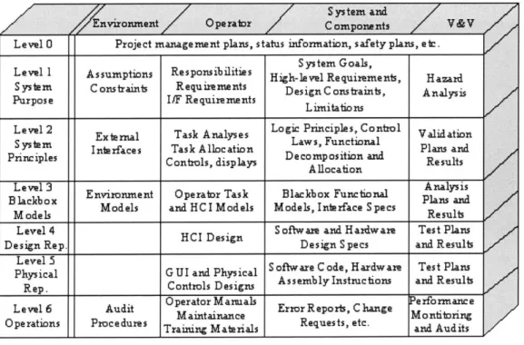
There are seven levels in an intent specification as seen in Figure 1 [14]. Levels do not represent refinement, as in other more common hierarchical structures, but instead each level of an intent specification represents a completely different model of the same system and supports a
different type of reasoning about it: each model or level presents a complete view of the system, but from a different perspective. The model at each level may be described in terms of a different set of attributes or language. Refinement and decomposition occurs within each level of the specification, rather than between levels [14].
The top level (Level 0) provides a project management view and insight into the relationship between the plans and project development. Level 1 of an intent specification is the customer view and assists system engineers and customers in agreeing on what should be built and whether that has been accomplished. It includes system goals, high-level requirements, design constraints, hazards, environmental assumptions, and system limitations. The second level, System Design Principles, is the system engineering level and allows engineers to reason about the system in terms of the physical principles and laws upon which the system design is based.
Level 0 Project manage ment plans, status information, safety plans, e te. S ys tem Goals,
Level 1 Assumptions Res ponsibilities High-le vel Re quirements, H azard System Cotraint, Requirements DesignConstraints, Analysis Purpos e I/F Re quirements Lmitations
Level 2 External Task Analyses Logic Principles, Control Validation S ystem Interfaces Task Allocation Laws, Functional Plans and
Principles Controls, displays De comp osition and Results Allocation
Level 3 Environment Operator Task Blackbox Functional Analysis Slackbox Models and HCI Models Models, Interface S pecs Plans and
M ode ls Results
Level 4 D S oftware and H ardware Test Plans Design Rep. HCI Design Design Specs and Results
Physical GUI ard Physical S oftware Code, Hardware Test Plans Rep. Controls Designs AssemblyInstmctions and Result Level 6 Audit Operator Manals Error Reports, C hange Performance Operations Procedures Tr nti teals Requests, etc. ari Adits
Figure 2. Intent Specification Hierarchy
The third, or Blackbox Behavior level, enhances reasoning about the logical design of the system as a whole and the interactions between the components as well as the functional state without being distracted by implementation issues. This level acts as an unambiguous interface between systems engineering and component engineering to assist in communication and review
of component blackbox behavioral requirements and to reason about the combined behaviour of individual c omponents u sing informal r eview, formal a nalysis, and s imulation. T he 1 anguage used on this level, SpecTRM-RL, has a formal foundation so it can be executed and subjected to formal analysis while still being readable with minimal training and expertise in discrete math.
The next two levels provide the information necessary to reason about individual component d esign a nd i mplementation i ssues. F inally, t he s ixth 1 evel p rovides a view of the operational system. Each level is mapped to the levels above and below it. These mappings provide the relational information that allows reasoning across the hierarchical levels and tracing from high-level requirements down to implementation and vice versa.
Intent information represents the design rationale upon which the specification is based. This design rationale is integrated directly into the specification. Each level also contains information about underlying assumptions upon which the design and validation is based. Assumptions are especially important in operational safety analyses. When conditions change such that the assumptions are no longer true, then a new safety analysis should be triggered. These assumptions may be included in a safety analysis document (or at least should be), but are not usually traced to the parts of the implementation they affect. Thus even if the system safety engineer knows that a safety analysis assumption has changed (e.g., pacemakers are now being used on children rather than the adults for which the device was originally designed and validated), it is a very difficult and resource-intensive process to determine which parts of the design used that assumption [14].
The safety information system or database is often separated from the development database and specifications. In the worst case, system and software safety engineers carefully perform analyses that have no effect on the system design because the information is not contained within the decision-making environment of the design engineers and they do not have access to it during system design. By the time they get the information (usually in the form of a critique of the design late in the development process), it is often ignored or argued away because changing the design at that time is too costly. Intent specifications integrate the safety database and information into the development specifications and database so that the information needed by engineers to make appropriate tradeoffs and design decisions is readily available [14].
Interface specifications and specification of important aspects of environmental components are also integrated into the intent specification, as are human factors and human interface design. The separation of human-automation interface design from the main system and component design can lead to serious deficiencies in each. Finally, each level of the intent specification includes a specification of the requirements and results of verification and validation activities of the information at that specification level [14].
SpecTRM, which stands for Specification Toolkit and Requirements Methodology, is a development environment that allows users to easily create, modify and analyze intent specifications. SpecTRM includes many features important to the intent specification process. First, an empty intent specification in SpecTRM contains headings that, when filled out, help ensure specification completeness. By providing the user with an initial structure to their specification, SpecTRM helps the user to think about aspects they may have otherwise left out. Second, SpecTRM provides an easy link creator. Links between levels provide traceability within the specification from the highest requirements all the way down to implementation. This is especially useful for tracking c hanges and p erforming interface t esting. F inally, S pecTRM provides various analyses that can be performed on the Level 3 blackbox model [25].
3.1.1 Analyses
SpecTRM currently provides two analyses that can be performed on the individual intent specifications: non-determinism and robustness. A model is deterministic if for any given system state and set of inputs, there is only one transition for each state and mode [25]. A model is robust, if for any given system state and set of inputs, a transition exists, i.e. a behavior is defined for all possible inputs [25]. These analyses allow the system engineers to eliminate all inconsistencies a nd i ncompleteness b efore t he s imulation i s r un. T he L evel 3 m odels c an b e checked automatically for these properties [7].
3.1.2 Simulations
SpecTRM models are executable. Because the Level 3 blackbox model is a formal representation of an underlying state machine, the model can be executed given a set of inputs.
Individual models can be executed in isolation and multiple models can be executed in an environment in which they interact with each other. Components can be linked to their parent subsystems and the subsystems to the controller to simulate the system-as-a-whole.
There are many benefits to running simulations in SpecTRM. First, simulations allow system developers to observe the results of interactions between components and the functionality of the subsystem specification and model. Testing blackbox behavior is especially important at this stage in the development lifecycle, because errors in the requirements specifications and/or the blackbox model can be uncovered before any code has been implemented. After the spacecraft has been created and deployed, changes will need to be made to the on-board software. Code maintenance comprises nearly 70% of the software lifecycle and changes to the software can be costly [26]. An executable state machine provides the software maintainers with the ability to incorporate changes to the code from the formal requirements specification, and simulate the effects those changes will have on the rest of the system, again before any code has been implemented. As evidenced by the SOHO accident described in Chapter 1, improper software change procedures can be as detrimental to a system as poor implementation of reuse.
Third, executable blackbox models help developers to perform trade-off analyses. Engineers can simulate alternative design strategies and determine which approach is most suitable given the constraints and requirements of the system. Finally, different types of visualizations of the underlying state machine allow users to facilitate the creation of a mental model of the system's functioning. A high quality mental model of the system will improve the requirements creation and reviewing process [3]. Clearly, having a formal, executable, blackbox model of the system provides engineers with the variety of benefits that aid in the proper implementation of a component-based development approach.
3.2 SpecTRM-GSC
Intent specifications provide the features needed to perform Component-Based Systems Engineering. As described in Chapter 2, the construction of a system using Component-Based Systems Engineering begins with a decomposition of the system. After the system has been decomposed into its subsequent subsystems and individual components, the system is developed
from t he b ottom-up. I n t he e xample g iven i n t his t hesis, t he c omponent intent s pecifications were constructed using SpecTRM. For spacecraft, the intent specifications were labeled SpecTRM-GSCs, or SpecTRM-Generic Spacecraft Components. There are four main characteristics of SpecTRM-GSCs that are crucial to the success of this technique: each component must be fully encapsulated, have well-defined interfaces, be reusable and contain component-level fault protection.
3.2.1 Fully Encapsulated
Each SpecTRM-GSC must b e fully encapsulated, m eaning that all the functionality o f that component should be contained within the component intent specification. Conventionally, much of the control and software for attitude determination and control components was traditionally distributed b etween the controller, the subsystem and component itself. By fully encapsulating the operations of each device within one intent specification, the m odularity o f design process and ease with which components are reused increases.
For example, a reaction wheel assembly will always receive torque commands as inputs. It then spins the reaction wheels to achieve the desired torque. Instead of associating these operations with the attitude determination and control subsystem (ADCS) from the beginning of development, an intent specification for the reaction wheel assembly is written independently of the ADCS, thereby disassociating the component from its possible uses. By capturing only what and how the reaction wheel assembly provides instead of what it will be used for, the component becomes far more modular not only between spacecraft but also within the same spacecraft. In other words, the component can be used in the ADCS of many different spacecraft as well as different subsystems of the same spacecraft. For example, in some extreme cases, thermal
subsystems can use the friction of the spinning reaction wheels to generate heat.
3.2.2 Well-Defined Interfaces
Like components in Component-Based Software Engineering, the SpecTRM-GSCs must also have well-defined interfaces. All components must adhere to standard naming conventions and input/output requirements. I t i s extremely important that the c onstruction o ft he Level 3
blackbox models of the SpecTRM-GSCs follow a consistent pattern in terms of how blackbox elements are named in order to avoid confusion and increase the ease with which components are combined to create subsystems. Consistency in the construction of the intent specifications is especially important in the case of inputs and outputs, because these are the modeling elements through which the components communicate with their parent subsystem. Therefore, a convention for both names and the type of information that the inputs and outputs transfer must be defined from the beginning of development and then strictly followed.
3.2.3 Generic
Because the components are fully encapsulated and have well-defined interfaces, they are also reusable. To enhance this reusability, specific information should be left out of the specification, making each SpecTRM-GSC highly generic. The system engineer inserts system-specific information when the components are used for a particular spacecraft subsystem. For example, when a digital sun sensor is used in an ADCS specification, the system engineer must specify the particular model being used and other information specific to that model number. If the sun sensor selected is the Adcole Digital Sun Sensor Model 18960, for example, the engineer must specify that the sun sensor uses a 15 bit input from its sensor heads. In the SpecTRM-GSCs, the use of both bold face and underlining highlights such information. These font characteristics alert the system engineer that the information is specific to a particular model number and should be changed when the generic component is instantiated in a particular
spacecraft design.
3.2.4 Component-Level Fault Protection
Component-Based Systems Engineering employs three levels of fault-protection: intra-component fault protection, inter-intra-component fault protection and inter-subsystem fault protection. These three levels ensure that fault protection covers the entire system; not only must the design account for component failures, but also for failures resulting from the interactions between components and subsystems. At the intra-component level, the fault protection logic assures that if the component is working in an off-nominal mode, it will alert its subsystem.
Then, at the inter-component level, the subsystem determines how to handle that fault. T his feature is especially important in autonomous spacecraft.
3.3 Summary
Intent specifications and SpecTRM provide a platform upon which Component-Based System Engineering can be performed. SpecTRM-GSCs help to capture domain knowledge through recording the rationale behind decision-making at each step in the development lifecycle. They abstract away the details of design so that the specifications can be reusable from one project to the next. Various analyses can be performed on SpecTRM-GSCs, which aids in the development of autonomous systems. System performance can be tested through simulation before any hardware is built or any code is written. During maintenance, changes to the software can be easily documented and incorporated into the new system. Engineers can also simulate design alternatives for trade-off analyses as well as visualize the underlying state machine to obtain a different perspective of the system. Most important, SpecTRM-GSCs grant users the benefits of reuse without the potential drawbacks. The next chapter provides an example of Component-Based Systems Engineering using SpecTRM as applied to a real spacecraft.
Chapter 4
SPHERES Example
SPHERES stands for Synchronize Position Hold Engage Reorient Experimental Satellites. It was created by the MIT's Space Systems Laboratory to provide NASA and the Air Force with a reusable, space-based test-bed for high-risk metrology, control and autonomy technologies [17]. T hese t echnologies are critical to the operation of distributed s atellite and docking missions such as the Terrestrial Planet Finder and Orbital Express. In addition, guest scientists from around the world will have access to this test-bed so they can independently design, code and debug estimation, control and autonomy algorithms for testing in the micro-gravity conditions of space (SPHERES will operate aboard the International Space Station) [9]. The experiments performed by NASA, the Air Force and the guest scientists are an important step in making many future space missions possible, especially those that require the ability to autonomously coordinate and synchronize multiple spacecraft in tightly controlled spatial configurations.
SPHERES was chosen as the case study for testing Component-Based Systems Engineering for many important reasons. First, S PHERES is an autonomous system. I t was created to execute maneuvers without the guidance of a ground controller. In fact, the only interactions the astronauts aboard the ISS have with the SPHERES system involves simply loading programs and replenishables onto the spheres. Since Component-Based Systems Engineering was developed to support autonomous spacecraft, it was important to test the technique on an autonomous system. Along the same lines, it was also important that the system be highly modular to test the component-based aspects of the technique. Third, and most essential to the research, was the need to test the technique on a real system. In order to evaluate the scalability and applicability of this method, it was critical to test the process on a real spacecraft system. These three criteria made SPHERES an excellent experimental subject for testing Component-Based Systems Engineering. This chapter describes the process of reverse-engineering SPHERES using the Component-Based Systems Engineering approach, which involved (1) outlining the structure of SPHERES, (2) creating SpecTRM-GSCs from the
SPHERES project, (3) creating two example Guest Scientist Programs and (4) performing analyses on the SpecTRM-GSCs.
4.1 SpecTRM-GSC Structure
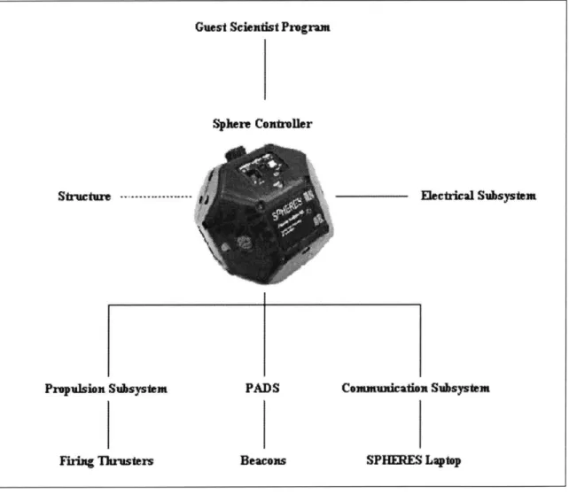
As outlined in Chapter 2, the first step in performing Component-Based Systems Engineering is a functional decomposition of the spacecraft. Figure 3 illustrates the SPHERES decomposition. SPHERES can operate with one, two or three spheres.
Guest Sciendtt Program
Sphere Centroller
Structure
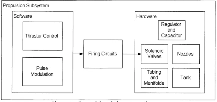
---Propulsion Subsystem PADS
Firing Thrusters Beacons
Electrical Subsystem
Cemundcatiox Subsystem
SPHERES Laptp
Figure 3. SPHERES Functional Decomposition
Each node in the decomposition tree represents a different SpecTRM-GSC, or intent specification. At the highest level is the Sphere Controller. The Sphere Controller provides the