Publisher’s version / Version de l'éditeur:
Vous avez des questions? Nous pouvons vous aider. Pour communiquer directement avec un auteur, consultez la première page de la revue dans laquelle son article a été publié afin de trouver ses coordonnées. Si vous n’arrivez pas à les repérer, communiquez avec nous à [email protected].
Questions? Contact the NRC Publications Archive team at
[email protected]. If you wish to email the authors directly, please see the first page of the publication for their contact information.
https://publications-cnrc.canada.ca/fra/droits
L’accès à ce site Web et l’utilisation de son contenu sont assujettis aux conditions présentées dans le site LISEZ CES CONDITIONS ATTENTIVEMENT AVANT D’UTILISER CE SITE WEB.
Building Research Note, 1972-04
READ THESE TERMS AND CONDITIONS CAREFULLY BEFORE USING THIS WEBSITE. https://nrc-publications.canada.ca/eng/copyright
NRC Publications Archive Record / Notice des Archives des publications du CNRC : https://nrc-publications.canada.ca/eng/view/object/?id=04e52074-37cf-419a-9320-ab5d01eceb50 https://publications-cnrc.canada.ca/fra/voir/objet/?id=04e52074-37cf-419a-9320-ab5d01eceb50
NRC Publications Archive
Archives des publications du CNRC
This publication could be one of several versions: author’s original, accepted manuscript or the publisher’s version. / La version de cette publication peut être l’une des suivantes : la version prépublication de l’auteur, la version acceptée du manuscrit ou la version de l’éditeur.
For the publisher’s version, please access the DOI link below./ Pour consulter la version de l’éditeur, utilisez le lien DOI ci-dessous.
https://doi.org/10.4224/40000625
Access and use of this website and the material on it are subject to the Terms and Conditions set forth at
Remote measurement of large deflections in fire tests
THl
B92
1
no. 84I
c. 2 I
- - - -
REMOTE MEASUREMENT
OF
LARGE
DEFLECTIONSIN
FIFCE TESTS
by
T.T.
Lie and J . E . Berndt
-- P l V l S l Q N O F B U I L D I N G R E S E A R C H
-
N A T I O N A L R E S E A R C H C O U N C t L Q T T A W A C A N A D A OttawaREMOTE MEASUREMENT O F
LARGE
DEFLECTIONSEN
FIRE TESTSby
T . T . Lie and J . E . Berndt
In experimental investigations of the fire resistive properties
of structural elements it i s often nece a s a r y to measure large deflections of t e s t specimens. The simplest a n d m o s t commonmethod of d e t e r - m i n i n g deflections makes u s e a£ a calibrated tape or rule. Taking such measurements during the course of a fire t e s t has, however, become
hazardous and difficult owing t o the increasing u s e of materials that
develop combustion products that may be toxic or reduce visibility.
Remote recording of the deflections is therefore desirable. Such a remote recording system must
a) record deflections of up to 2 0 in, as a function of
t h e ;
b) be reliable at temperatures in a range f r o m room
temperature to about 1 50
OF;
c ) be capable of u s e in an environment of dense smoke;
d)
be
small (so that it can be i n s e r t e d between hydraulicjacks such as those used in the laboratory of DBR/NRC
for applying a load during a fire t e s t ) .
A survey of the literature indicates that although n u m e r o u s versions of
displacement-measuring devices have evolved there are none tbat completely
satisfy the above requirements.
An
attempt has t h e r e f o r e been madet o design and construct an appropriate device.
In general, t w o methods are used for measuring large dis- placements [ 1 3 ,
i.
e , optical and electro-mechanical. Because ofthe possibility of s m o k e development during a t e s t , optical methods w e r e n ~ t considered in this case. Of the various electro-mechanical techniques one was chosen in which the displacement of a certain point
on a t e s t specimen could be converted into an electrical signal with the aid of a linear potentiometer, Such conversions are described in
References 2 , 3 and 4.
A d e v i c e was constructed that could measure displacements in
(Figure l ) , simple to operate,
and
can be constructed at a low cost (approximately $ 2 0 f o r material and 7 hours of labour, based on theconstruction of five units by DBR/NRC).
DESCRIPTION
OF
DEVICEThe device is shown in Figure 1. Components include: I , Aluminum frame.
2 . Pulley onto which a steel wire, 0 . 0 1 -in. diameter, is wound. The s t e e l w i r e i s connected at the point where displacement is
t o be measured. The cavity of the pulley contains a spring f r o m
a
standard 8-ft steel measuring tape. Thespring
keeps the wire taut as it unwinds from the pulley. The maximum forceexerted by the spring i s 1 2 5 g .
3 . C o v e r plate of aluminum that prevents the spring from escaping
from the cavity.
4. S c r e w w i t h a slot t o f i t t h e end of the tape spring.
5. Nut to lock the screw (paint 41 and thus the end of the tape spring.
Locking is done by tightening the nut against the frame [I).
6 .
Magnet t ofix
the device at a suitable location during the test.7. S c r e w to attach the magnet ts the frame (point 1 ) .
8 . Three-pin plug used t o connect a three-wire cable to the potentiometer (point
9).
9 . Ten-turn l i n e a r potentiometer (resistance 1 kfl f 3 per cent, tem- perature coefficient 11.11 x
IO'~/F
deg, temperature range - 8 5 to185"F, linearity 0 . 2 5 per cent). The potentiometer is fastened to the f r a m e (point 1) with the aid of the nuts (points 10 and 1 2 ) and toothed lock washer (paint I I ) . The pulley (point 2) is secured to
the shaft of the potentiometer by means of f i e screw (point 1 3 ) .
PERFORMANCE AND CE-XARAGTERETIGS
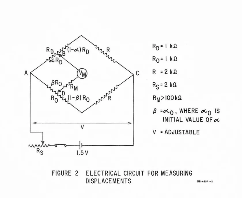
A potentiometer (ELD) is placed in an arm of a Wheatstone Bridge (Figure 2 ) . A suitable range f o r
VM
is 100rnV,as this corresponds tothe normal range of output of t h e m a c o u p l e s used in f i r e t e s t s . Thus the same meters, usually multipoint recorders, can be used f o r rneasur
-
ing both temperature and deflection.The
maximum
deflection of interest in f i r e t e s t s is about 20 in.T o obtain 100 m V for
a
deflection of ZO in., each inch of deflectionshould be converted into 5
m V
meter output voltageVM. The
methodof calculating
VM
is described in Appendix A,and
suitable values ofthe bridge resistances and voltage
V,
f o r a sensitivity of5
m V
per inch deflection, are given in Figure. 2 and Appendix A .h practice the sensitivity of the circuit is adjusted to the desired value by varying the voltage
V.
Once the sensitivity is set, the outputvoltage to the meter VM i s zeroed by varying the resistance between AD. At r o o m temperature the main errors in the displacements
measured by the device are caused by non-linearities of the bridge and
potentiometer (RD), and by the eccentricity and imperfect roundness of
the pulley. Calibration shows that the t o t a l error resulting from these causes i s l e s s than 3 per cent f o r deflections in the range of 0 . 2 5 to I in. and
less than 1 per cent for higher deflections. Another possible error is
that associated with defamation of the steel wire under dynamic f o r c e s
caused bymovement of the t e s t specimen. W h e n these forces are not
greater than approximately 150 g the e r r o r i s negligible.
In
fire t e s t s the rateof
deflection of t e s t specimens is usually within t h s e limits.At higher temperatures errors in displacement measurements
are mainly due to
a) change in the resistance of the potentimeter that converts displacement into electric current
(RD]
b) expansion of the pulley
c) expansion of the steel. wire.
These e r r o r s can be large, but they c a n be reduced by choice of suitable values f o r the potentiometer resistances and wire lengths. Because errors tend t o compensate for each 0 t h ~ ~ the t o t a l error c a n
be made negligibly small.
Change in the resistance of
RD
with temperature rise will causean increase in the reading of t h e meter
VM.
B y using small initial values ofa
and 0, f o r exasnple 0.05, the e r r o r can be made quite small,This c a n be done by turning the pulley about one half turn caunter-
clockwise from i t s r e s t position and attaching the wire to the test specjmen.
A s shown in Appendix B , the meter w i l l then give in the range of deflections
of 1 to 20 in. a reading that is approximately 0 . 3 per cent too high when the ambient temperature r i s e s by 9 0 F deg ,
The err or due t o expansion of the aluminurn pulley and that
due to expansion of the steel wire tend to compensate each other. B y choosing suitable lengths f o r that part
of
the wire on the pulley(ap)
and that between the pulley and the t e s t specimen(a,),
the angularposition of the pulley can be made insensitive to temperature.
It
isshown
in
Appendix C that this is true when fl=
0.4375 lo. Thus f o r Pa
value ofR
P
= 2 5 in.,
a suitable length f o r measuring deflectionsof
fire t e s t specimens, A. should be approximately 57 in.
Def lectians of the specimen will alter the ratio of to Lo and
thus introduce
a
small error due t o temperature effect.#
or anambient temperature r i s e of 90 F deg the e r r o r is of the order of
0 . 2 per cent
in
the range of deflections under study (0 to 20 in. ). This e r r o r causes t o o low a meter reading, and it practically compensates the error of 0.3 per cent due to change of resistance of the potentiometer with temperature. As a consequence, in the range of deflections from1 to 20 in. and at temperatures up t o about 90 F deg above room tem-
perature the total error w i l l be approximately the same as that at r o o m temperature, i . e . less than 1 per cent.
REFERENCES
1 . W a r d , H. S . Some Reasons and Techniques for M e a s u r i n g L a r g e Structural Displacements. The Engineering Journal,
Vol.
54, No. 6 , 1971, p. 14-21.2 . Lebow, M . J . S o m e Principles of Transducer Design. ISA
Transactions, Vol. 2,
No.
1,1963,
p. 85-92.3. Chudnovskii,
V.
Y.
,
M . P. K o r o l , andV.
G . Zagorodnii. Converter f o r Large Linear Displacements. MeasurementTechniques, Vol. 13, No. 3, 1970, p. 339-340.
4. Burn, K. N. Instrumentation f o r a Consolidation Study of a Clay Deposit Beneath an Embanhnent. Geotechnique, Vol.
IX,
APPENDIX A ELECTRIGAL CIRCUIT
B y
applying Kirc?hofFs law to circuitsABC,
ABD and BCD(Figure
2) the equations f o r the currents t h o u g h these circuits canbe set up. Solving the equationsgivesthe current through the meter,
and f r o m this the voltage
V
betweenB
and D can be derived. F o r a meter having a resistance%igh in comparison with the resistancesin the a r m s of the bridge, the voltage
VM
c a n be given byT o obtain a reading of 100
m V
for a deflection of 20in.,
variouscambinations of values of bridge resistances and supply voltage V can
be chosen.
It
c a n be verified by means of Equation ( 1 ) that for a pulleywith a diameter of 2 in. the above requirement c a n be satisfied by the following c m b i n a t i o n
a
w h e r e b o i s the initialvalue o f u0'
(approximately 0.05, corresponding to about one half turn counterclockwise
of the potentiometer
+
from its restposition)
approximately 30.0 IT m V , adjustable.
In
practice,V
is adjusted during the calibration of the device at a valueAPPENDIX
B
ERROR
DUE TO
CHANGEOF
RESISTANCEOF
THE POTENTIOMETERThe error caused by a change in the resistance of the potentio-
meter of the device
RD
(Figure 2 ) can be calculated by means of Equation 1 ),T o keep the error small it is essential to make the initial value
a
.
ofa
small. T h i s implies that B, which is adjusted so as t o equala0
tomake
VM
zero at the start of the t e s t , is small. a l s o ,F o r R = 0 . 05, a temperature coefficient of resistance
RD
of11. 11 x ~ O - ~ / F deg, a temperature rise of 90
F
deg and l -in. deflection1
(a
=
0.05+
lOrrD
,
where D is the diameter of the pulley) it followsfrom Equation C1) that
Because at the initial temperature the voltage
VM
is 5m V ,
the error resulting from a temperature rise in the potentiometer of 90 F deg isthus 0.012675 m V , or roughly 0.3 per cent.
In
the s a m e way, f o ra
deflection of 20 in. the e r r o r due t o a temperature rise of 9 0
F
deg i sAPPENDIX
G
ERROR D U E T O EXPANSION O F P U L L E Y AND W I R E WITH
NO
DEFLECTION
OF
THE TEST SPECIMENIt
is a s s u m e d that the wire, with less than four turns woundround the pulley, will slip over the pulley when it expands. This assumption has been verified by heating only the pulley and observing
the change of the voltage
VM.
B y choosing suitable lengths of wire f o r t h e pulley and the wire
between the pulley and t e s t specimen it is possible to make the zero
position of the pulley insensitive to temperature. The condition is that
at any temperature
1 9 - a = n i-r
D2
0 D
where
A s
=
the total wire length at the temperature under consideration .to=
initial w i r e length between pulley and t e s t specimenn
=
initial numberof
turns of s t e e l wire on the pulley8
Dr = diameter of the pulley at the temperature under con- sideration.
A' can be written as
at
= A (1 -t-a,
T)w h e r e
R
=: the length of the steel wire at r o o m temperatureas
=
the expansion coefficient of steelT = temperafxre o f t h e w i r e .
Dt can be w r i t t e n as
where
D
=
the diameter of the pulley at r o o m temperatureaa
=
the expansion coefficient of aluminum.n can be written as
0 A
where
= the length of the steel w i r e on the pulley at r o o m
temperature.
From Equations (2-51, it is possible to make the zero position of the pulley independent of temperature, when
- 6
- 6
or for
a
=
7 x 1 0 /F d e g a n dm a =
2 3 x 10/F
deg whenS
For
R
=
2 5 in., the length As of the steel wire between pulley andP
t e s t specimen should be 5 7 . 1 4 in. to make the zero position of the pulley insensitive t o temperature.
APPENDIX
D
ERROR
DUE
TO
EXFANSIONOF
PULLEY
AND WJRE WHEN TESTSPECIMEN DEFLECTS
When there is deflection, the equation for the position of the pulley will be
where
t
=
the length of the steel wire between pulley and t e s tspecimen at time t after the start of the deflection
n
=
the number of turns of the steel wire on the pulley att
time t .
The movement of the pulley at time t i s no - nt turns. T h i s
will cause a change in t h e indication of the miflivolt meter of
Substitution
in
Equation(8)
ofR
1'-
4
n=
2
a n d n 7 33n D
t r D f gives- 6
-6F o r Ap = 25 in., I
=
57.14 in.,a,
=
7 x 10 ]OF,a
=
23 x 10/OF,
a-with a deflection of 1 in. ( B t = 58.14 in. ), the indication of the meter
becrrmes
G
=
4 . 9 8 9 6 8m V .
This indicates a meter reading that is approximately 0 . 2 1 per cent too
low. In the same way it can be shown that f o r a deflection of 20 in, t h e meter reading will be approximately 0 . 1 9 per cent too low. The error
due to expansion of the pulley and the steel wire is thus roughly 0.2