Publisher’s version / Version de l'éditeur:
Journal of Sound and Vibration, 33, March 1, pp. 103-115, 1974-03-01
READ THESE TERMS AND CONDITIONS CAREFULLY BEFORE USING THIS WEBSITE. https://nrc-publications.canada.ca/eng/copyright
Vous avez des questions? Nous pouvons vous aider. Pour communiquer directement avec un auteur, consultez la première page de la revue dans laquelle son article a été publié afin de trouver ses coordonnées. Si vous n’arrivez pas à les repérer, communiquez avec nous à PublicationsArchive-ArchivesPublications@nrc-cnrc.gc.ca.
Questions? Contact the NRC Publications Archive team at
PublicationsArchive-ArchivesPublications@nrc-cnrc.gc.ca. If you wish to email the authors directly, please see the first page of the publication for their contact information.
NRC Publications Archive
Archives des publications du CNRC
This publication could be one of several versions: author’s original, accepted manuscript or the publisher’s version. / La version de cette publication peut être l’une des suivantes : la version prépublication de l’auteur, la version acceptée du manuscrit ou la version de l’éditeur.
Access and use of this website and the material on it are subject to the Terms and Conditions set forth at
The impact insulation assessent of covered concrete floors
Ford, R. D.; Hothersall, D. C.; Warnock, A. C. C.
https://publications-cnrc.canada.ca/fra/droits
L’accès à ce site Web et l’utilisation de son contenu sont assujettis aux conditions présentées dans le site LISEZ CES CONDITIONS ATTENTIVEMENT AVANT D’UTILISER CE SITE WEB.
NRC Publications Record / Notice d'Archives des publications de CNRC:
https://nrc-publications.canada.ca/eng/view/object/?id=4e36b526-b6fe-4672-ac88-cdadc0a1c59b https://publications-cnrc.canada.ca/fra/voir/objet/?id=4e36b526-b6fe-4672-ac88-cdadc0a1c59bL E S PLANCI-IERS D E B E T O K COUV l n e
>
c h o c s c l a s s l q u e e s t l a m 6 t h o d e d ' e s 2 c h o c s . I1 e s t n h c e s s a l r e d e c o n n a i t r e l e c h a m p s o n o r e p r o d u l t p a r m a c h 1 n e 5 c h o c s s u r l e p l a n c h e r n u e t l e s s p e c t r e s d e f o r c e d u m d r t s u r l e p l d n c h e r n u c t l e p l a l l c h e r c o u v e r t . L e s rCsu1L;lts c d l ~ u s ' a c c o r d e n t b l e n d v e c l e s d o n n C e s ~ n e s u r 6 c s . C e l d c o n f l r m e l a d C f ~ n l t d u c o m p o r t e m e n t d ' u n r e v f t c m e n t d e s o l e n t e r m e s d ' a r n 6 l l o r d t 1 o n l ' l s o l a t l o n d e s ~ m p a c t s e n c e q u l c o n c e r n e l e s p l a n c h e r s d e d d l l e s s r e v g t e m e n t s d e s o l m o u s .Journal of Sound and Vibration (1974) 33(1), 103-1 15
THE IMPACT INSULATION ASSESSMENT O F COVERED
CONCRETE FLOORS
Acolrstics Crourp, Departmeilt of Puure and Applied Physics, University of Salford, Salford MS 4 WT, Eizglaizd
AND
A. C. C. WARNOCK
Burildiizg Physics Section, Division of Building Research, Natioizal Research Cozcizcil of Canada, Ottawa, Canada
(Received 15 August 1973, and in revised form 8 October 1973)
The standard tapping machine is the most commonly used source for impact insulation testing of floors and floor coverings. In this paper the stages of the transmission of impact noise through a floor are considered. The force spectrum of the hammer impulse is calcu- lated digitally. By assuming that the cushioning effect of the floor covering can be separated from the concrete floor on which it is laid, it is possible to predict the sound field produced by the tapping machine. It is necessary to know the sound field produced by the tapping machine on the bare floor and the force spectra of the hammer on the bare and the covered floor. The predicted results agree well with measured cases. This validates the definition of the behaviour of a floor covering in terms of impact insulation improvement when used on concrete slab floors. It also shows that impact insulation improvement can be calculated from a knowledge only of the hammer impact spectrum. An ageing or hardening process which occurs after successive hammer blows on soft floor coverings is also described.
1. INTRODUCTION
The criticisms of the International Standard Tapping Machine [I] and its use in evaluating floors for impact insulation are many and varied but, curiously, a great number of countries have adopted the machine as the impact source, the resultant noise spectrum then being compared with a national criterion which is regarded as acceptable.
The chief criticisms of the machine are that the force spectrum has a greater high frequency content than a footstep and that the forces involved are much greater than those applied in walking. Spectral analysis of the impact noise confirms that footsteps produce substantially lower sound pressure levels with a greater proportion a t low frequencies. All this would not in itself be important if the subjective evaluation of floors correlated well with results obtained by the tapping machine method but several authors have demonstrated that there can be appreciable variance and that the results depend upon the type of impact [2-61. Nevertheless, in spite of its inadequacies, the tapping machine will clearly be around for many years to come. I t must, therefore, be of benefit to understand more clearly the physical processes which are occurring. These processes have, to some extent, already been investigated in previous research work [7], in which analogue analysis of the force pulse spectra was under- taken.
In the work reported in this paper measurements of the force spectra have been determined digitally from the force pulses. The noise spectrum resulting from a hammer blow on a floor
104 R. D. FORD ET AL.
surface has been measured. The physical properties of one concrete floor have been determined from which predictions have been made of the impact noise transmission characteristics of the floor. The results show that the cushioning effect of a resilient floor covering can be separated from the effects of the concrete floor on which it is laid. This validates, for single concrete slabs, the method of defining the impact behaviour of a floor covering in terms of its impact insulation improvement [8]. Furthermore, it opens up the possibility of measuring the impact behaviour of the covering by studying just the impact, so obviating the need for a special reverberant test room and sound measuring equipment. A possible longer term benefit could be an appreciation of those properties which are desirable in a floor covering material obtained by studying the shape of the impact force history. This paper shows that an ageing or hardening process occurs during impact tests on thick carpet which must be taken into account if accurate impact tests are to be performed.
2. APPROACH T O THE PROBLEM
The most promising theoretical approach to the problem of a concrete floor slab radiating sound as a result of being struck impulsively is outlined in the appendix of reference [7]. Energy enters the slab during the impulse and at the same time energy is absorbed due to natural damping processes. The slab is assumed to be a reverberant system so that the energy balance equation yields
p2 = F 2 N
Zq2n f M S ' (1)
where V 2 is the mean square velocity of the slab, F 2 is the mean square force of one impulse averaged over one second, N is the number of impulses per second, Z is the point impedance of the slab, q is the loss factor of the slab, M its mass per unit area and S its surface area.
V 2
and F2 usually refer to frequency bands (for example,+
octaves) and Z and q are both functions of frequency.The radiated sound power is
W = R S V 2 , (2)
where R is the radiation factor and is another function of frequency. Finally, the sound pressure level in a room below the slab is dependent upon the room absorption: i.e.,
where
p2
is the mean square pressure, pc is the characteristic impedance of air and A is the absorption of the room.The whole method is in terms of energy and, although the original source is impulsive, the energy is averaged out to long term mean values. Even this simplified approach is difficult to use in practice because of the uncertainty in defining values for Z , q and R for the slab and F2 for the impulse.
The premise in this paper is that for a concrete slab, either alone or with a resilient covering such as vinyl or carpet, 2, q and R are functions of the slab alone and are independent of any resilient layer. The resilient layer, through its resilient properties, affects F' by modifying
the force history of the impulse. It should be possible, therefore, to obtain the force spectrum by analysing the impulse.
At low frequencies, Z is greatly coloured by a few major resonances, but at medium and high frequencies its average value over a frequency band should tend to
IMPACT INSULATION OF COVERED FLOORS 105 where B is the cylindrical bending stiffness of the slab. Again, at low frequencies, R is deter- mined by the slab geometry and the resonances, but above the critical frequency its value should tend to that of the characteristic impedance of air. The damping depends primarily on the edge mounting conditions of the slab and must be measured.
The object, then, is to measure as many of the parameters as is possible and to test the premise that, for a given floor slab, the resulting sound level is directly related to the impulsive forcing function. The transfer function of the slab is defined as the ratio of the radiated sound power to the mean square input force: i.e.,
The supposition is that G is independent of the floor covering, the effect of which is contained in the force spectrum.
Although G can be broken down into smaller parts, as discussed before, from the experi- mental point of view it may be more useful to measure the transfer function directly. The force spectrum is available from the Fourier transform of the impulse. The radiated sound power may be obtained by carrying out a normal impact test on the floor slab by using the tapping machine, which gives 10 impacts per second.
I S 0 Impact Transmission test results may be quoted in terms of the sound pressure level (ISPL) in the room below the floor. This is the
Q
octave sound pressure level in the room corrected for 10 m2 of absorption. From equation (3), for 10 m2 of absorption,or
ISPL = PWL - 4 dB,
where PWL is the radiated sound power level in a
Q
octave band r e 10-l2 watts. Now, from equation (4)G
-- -
-.-
W 110-l2 10-l2 F2 1 0 ' and therefore
10 log,,
(&)
= ISPL - 6 dB, ( 6 )where F L is the force level in a
3
octave band in dB r e 1 N, i.e., 2010g,,F, for one impact per second.The impact insulation improvement of a covering on a concrete floor is given by (ISPL)barc f l o o r - (lSPL)covcrcd floor.
If, as is assumed, the transfer function is independent of the floor covering, then Impact insulation improvement = F L co,,cre,c - FL,,,,
,,,,.
106 R. D. FORD ET AL. 3 . EXPERIMENT
3.1. IMPACT PULSES FROM THE TAPPING MACHINE HAMMER
The standard I S 0 tapping machine hammer is constructed of steel and brass. It weighs 0.5 kg and falls 41 mm t o the test surface. The hammers are restrained on the first rebound. Because of its construction the hammer itself is very rigid and when it falls upon a very hard surface such as concrete the impact is short and sharp. By considering the blow as a n impulsive force of constant value F, for time T , limiting values can be deduced. The impact velocity of the hammer is 0.89 ms-'. The impulse FcT must equal the change of momentum of the hammer. Thus, for a perfect rebound, if m is the mass and uo the impact velocity,
More generally, if K is the coefficient of restitution,
If K = 0 the minimum value of the impulse is 0.445 Ns.
In order t o make a more detailed study of the force history of a hammer blow o n various surfaces, a single specimen hammer was constructed with characteristics identical t o those of a tapping machine hammer. Its motion was measured by an internally mounted acceler- ometer. If it is assumed that the hammer is a rigid body, Newton's second law may be used t o determine the force which it imparts. Because of limitations of the electronic instrumentation the system did not operate down t o zero frequency, but cut off at -2 Hz. This meant that the accelerations when the hammer was in the air were not measured, but the error is small since the acceleration during impact is relatively large.
The impact pulses observed must be considered as those from the tapping machine in perfect condition. In normal tests it is difficult t o get the correct distance of hammer fall for every hammer and t o ensure that the head strikes the surface squarely. On concrete the repeated blows tend t o fracture the surface quite rapidly, producing fine sand. This may also expose any large diameter aggregate, creating an uneven surface. On carpets, evidence will be given that repeated impacts change the properties of the carpet.
TABLE 1
Samples used in the tests
Concrete floor Sample Sample no.
Building Physics (a) Bare concrete 1 n
Section N.R.C. (2.4 m Permapolisli Vinyl 2
Ottawa x 2.4 m Permapolish Vinyl on 2 mm cork 3
x 0.10 m)
Acoustics Group (b) Bare concrete l b
University of (2.97 m Felt ( 4 mm thick) 4
Salford England x 2.97 m Rubber bound felt (4 mm thick) 5
x 0.17 m) Rubber backed pile carpet 6
Impact pulses for hammer blows o n several surfaces were investigated. These are described in Table 1. Two specimen pulses are shown in Plate 1. Plate I(a) is for the hammer on bare concrete. The pulse width is -0.4 ms and the height is -5000 N. The signal in this case was passed through a 4.5 kHz low pass filter t o reduce the effects of ringing of the hammer. T h e oscillating tail of the pulse is due t o the filter but does not affect the spectral analysis below the cut-off frequency. Plate l(b) is the impulse o n a soft carpet (sample (6)); the width is -8 ms
Plate 1. Tapping machine hammer impulses (a) on bare concrete and (b) on soft carpet (sample (6)).
Plate 2. Tapping machine harnnler impulses on soft carpet (sample (6)). The traces were taken simul- taneously, the upper from a detector in the hammer, the lower from a detector in the floor.
IMPACT INSULATION OF COVERED FLOORS 107 and the height 150 N. A lack of symmetry about the maximum value is more pronounced here, which is probably due to the energy losses (damping) within the sample. Pulses for other samples lay between these extremes.
In order to check that the impulsive force measured by the accelerometer was equal t o the force transmitted to the floor, the hammer was dropped on to a piezoelectric ceramic disc, cemented into a concrete floor. The voltage output from the disc was related to the applied force by a step loading method. The assumption was made that this calibration could be applied to the dynamic case and that the disc response was not dependent on the area over which the force was applied. Traces from the accelerometer and the disc, with sample (6) on the floor, are shown in Plate 2. Within the accuracy of the experiment the traces appear identical. Similar results were obtained with other samples.
The mean square force per Hertz F,(f) of the impact pulse F(t), which begins at t = 0 and ends at t = T, is determined in a single sided spectrum given by
F;(,f) = 2 F ( t ) exp (2rrvt) d t
I6
The mean square force in a
4
octave band ofcentre frequency fo, which ranges from frequenciesfl tofz(f2 >,fJ is
f2
F 2 ( h ) =
1
lFl(f)12df (8)f l
At frequencies less than about 1/4T the slope of the pulse is not important and it can be replaced by a boxcar function, as discussed in section 3. I, of width T a n d height F,, where
Thus, from equation (7)
and for a
Q
octave with centre frequency foEquation (10) is plotted for an impact with K values of 0 and 1 as dotted lines in Figures 1 and 2.
Three methods may be used to analyse the pulses at higher frequencies : analytical, analogue or digital.
Major problems arise in the analogue method due to the short signal duration, although this method has been used with success elsewhere [7]. The analytical procedure involves fitting a function to the observed pulse shape and solving equation (8). The half wavelength sinusoidal pulse has been commonly used. There are two drawbacks to this representation: first, discontinuities occur at the beginning and end of the curve and, second, a symmetry about the maximum is assumed which may not exist in practice (see Plate l(b)). Preliminary investigations suggest that a polynon~ial of about nine coefficients could be used to describe the pulse reasonably accurately.
The digital method of determining the spectrum was adopted as being the most accurate. The pulses were digitized by using a pencil follower system. The calculation of the Fourier
108 R. D. FORD ET AL.
transform was carried out by a standard integration method, in which logarithmic frequency increments were used. The accuracy of the calculations is better than 1 dB over the extent of the plotted curves, but some inaccuracies may have been introduced during the digitizing process.
Frequency (Hz)
Figure 1. Hammer forcespectra for oneimpact/second obtained by digital analysis ofexperimentalimpulses for several floor coverings. The coverings are described in Table 1.
Figure 2. Hammer force spectra for one impactlsecond obtained by digital analysis of experimental impulses for the first (I), 15th (11), 240th (111) and 5000th (IV) drop of the hammer on soft carpet (sample (6)).
IMPACT INSULATION OF COVERED FLOORS 109 The
+
octave r.m.s. force spectra as defined by equation (8) for each of the samples (1) to (5) are plotted in Figure 1 . The 3 dB/octave rise of the spectra at low frequencies as predicted in equation (10) can be seen. As expected, the effect extends to the highest frequencies for the pulses of shortest duration.In order to investigate the effect of many impacts on a single area of a compliant floor covering, the impact pulses of a hammer dropped on the same area for the lst, 15th, 240th and 5000th time were recorded. Since a single tapping machine hammer drops twice each second, the latter two figures correspond to tests lasting 2 minutes and 45 minutes, respectively. The spectra of these pulses for sample (6) are plotted in Figure 2. It can be seen that the high frequency content of the pulse increases with the number of previous impacts on the same area. This suggests that the stiffness of a carpet builds up with the amount of 'working' the carpet suffers. A full description of the effect could be achieved by an analysis of the impact
pulses.
It can be concluded that the impact test results on this type of carpet depend on the amount of "working" it has undergone and it is reasonable to assume that similar effects will occur due to wear and dirt. The average impact test lasts from about 2 minutes to 30 minutes depend- ing on the instrumentation so that a curve between that for 240 and 5000 impacts is probably most representative of the average force spectrum over the time of the test.
A similar effect, but much reduced, was observed for hammer blows on the harder fibre floor coverings, samples (4) and (5).
3.3. MEASUREMENT OF THE SOUND FIELD DURING IMPACT TESTING
Two floors were used for impact testing. These were concrete slabs of dimensions given in Table 1, which were set into the recesses in the ceilings of two reverberant rooms. Both slabs were freely resting at the edges. The samples tested on each floor are indicated in Table 1. The four tapping machine positions recommended by the ASTM [9] were adopted. In tests below floor (a), three microphone positions were used with a rotating vane; below floor (b), four microphone positions.
The results are quoted in terms of the ISPL, as defined in section 2. The results for the two concrete floors are given in Figure 3 and those for the various samples in Figures 7-1 1. The ASTM recommendation suggests that measurements should be made down to 50 Hz, but this was extended down to 3 1 Hz because, particularly with carpets, there is a comparatively
I I I I I I I 1
63 I25 250 500 1000 2000
Frequency (Hz)
Figure 3.
+
octave impact noise levels of the tapping machine on two bare concrete floors normalized to 10 mZ of absorption.R. D. FORD ET AL.
s
63 125 250 500 I003 2030
Frequency (Hz)
Figure 4. Transfer functions of the two concrete floors in 3 octave bands. The measured and calculated curves are shown.
large amount of radiated sound energy at low frequencies. The accuracy of the measurements at these frequencies is not expected to be great since it is doubtful whether a truly diffuse field existed in the rooms- used. The standard error in the results was always less than 1 dB for frequencies greater than 63 Hz and then rose to -2 dB on average at 25 Hz.
3.4. INVESTIGATION OF THE PROPERTIES OF THE FLOORS
The bare concrete floors are used as the standard or reference surfaces. The experimental transfer functions of the slabs have been obtained by substituting the measured ISPL's and the force spectrum for concrete into equation ( 6 ) , and they are shown in Figure 4. An attempt
was also made to calculate the transfer function of floor (a) from equation (5). The loss factor was determined in the following manner. The floor was excited in a particular octave frequency band by a vibrator. The average decaying signal from an accelerometer mounted at 3 positions on the floor was observed when the vibrator was stopped. If T 1 is the reverberation time of the floor, defined as the time taken for the energy to decay by 60 dB, then the loss factor is
given by
2.2
The centre frequency of the octave band isfo. The results are given in Table 2. At frequencies above 200 Hz (above the critical frequency) it may be assumed that the high frequency approximations for R and Z described in section 2 are valid. The damping has been measured, so a theoretical value of G may be obtained in the frequency range from 250 to 4000 Hz. This is shown in Figure 4 and lies about 3 dB above the measured value.
In order to investigate this discrepancy further, the velocity response of the bare concrete floor was measured when it was excited by the tapping machine. The velocity was obtained by integrating the acceleration measured on the underside of the slab. The velocity distribu- tion across the surface was uneven and altogether measurements were made at 13 locations in order to obtain a reliable root mean square value.
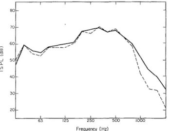
The four tapping machine positions recommended in the standard impact test were used. The velocity spectrum is shown in Figure 5 together with the calculated spectrum, as obtained by using the force spectrum for impact on concrete in Figure 1, the measured values of q and the high frequency approximation for Z in equation (1).
IMPACT INSULATION OF COVERED FLOORS
TABLE 2
The loss factor offloor ( a ) in octave bands
Octave b a n d
centre frequency M e a n value Loss factor
fo (Hz) of T 1 (s) 'l
Frequency ( H z )
Figure 5. Velocity of bare concrete floor (a) when excited by the tapping machine. The solid line is measured
4
octave band level, the dotted line is calculated.the
Frequency (Hz)
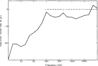
Figure 6 . Radiation factor (R) of bare concrete floor (a). The solid line is the calculated value for the 3 octave bandlevel, plotted in dB as lOlog,,(R/pc). The dotted line is the high frequency theoretical value.
112 R. D. FORD ET A L .
There is good agreement at the high frequencies and better agreement than might have been expected at the lower frequencies where individual resonances should predominate in the response.
"
63 125 2500
Frequency (Hz)
Figure 7. j- octave impact noise levels of tapping machine on Permapolish Vinyl (sample (2)), normalized to 10 m2 of absorption. The solid line is for the measured results, the dotted line for the calculated results.
1 I I I 1
63 125 250 500 1000
Frequency (Hz)
Figure 8. 3 octave impact noise levels of tapping machine on Permapolish Vinyl on 2 mm of cork (sample (3)), normalized t o 10 m2 of absorption. The solid line is for the measured results, the dotted line for the calculated results.
The radiation factor, R, may be calculated from equation (3), by using the measured velocity levels and the ISPL for the impact test on the bare concrete floor (a) (see Figure 3). This is shown in Figure 6 together with the high frequency theoretical value of pc. From 31 5 to 2500 Hz the measured radiation factor is consistently low by about 3 dB and so it appears that the discrepancy between the measured and calculated values of the transfer function is in the radiation term.
IMPACT INSULATION OF COVERED FLOORS 113
By using the experimental transfer function in Figure 4 and the corresponding force spectra from Figures 1 and 2, the ISPL's for the various floor coverings on concrete floors were calculated from equation (6). These are plotted in Figures 7-1 1 and can be compared with the
Frequency (Hz)
Figure 9. Q octave impact noise levels of tapping machine on felt carpet (sample (4)), normalized t o 10 mZ of absorption. The solid line is for the measured results, the dotted line for the calculated results.
Frequency (Hz)
Figure 10. JJoctave impact noise levels of tapping machine on rubber bound felt carpet (sample (5)), normalized t o 10 mZ of absorption. The solid line is for the measured results, the dotted line for the calculated results.
experimental levels. Generally, agreement is excellent. For sample (6) in Figure 11 the ISPL's predicted from the force spectra for the 1 st and 5000th blows are given. The latter gives better agreement a t high frequencies. Generally there is a random discrepancy between the calcu- lated and experimental values at low frequencies which is attributable to the difficulty in making accurate measurements in this area. At the highest frequencies the tailing off of the calculated results consistently occurs before the experimental results.
R . D. FORD ET AL.
20
'\
I I I I I
i
3 1 6 3 I25 250 500 Frequency (Hz)
Figure 11.
4
octave impact noise levels of tapping machine on soft carpet (sample (6)), normalized to 10 mZ of absorption. The solid line is for the measured results and the dotted lines show the calculatedresults for the 1st (I) and 5000th (IV) hammer blow.4. CONCLUSION
The transmission of impact noise through concrete slab floors, the source beinga standard tapping machine, has been investigated. By using a simple statistical treatment, and assuming that the action of the floor covering can be separated from the action of the floor, an expression for the transfer function of the floor has been deduced (equation (6)). From the transfer function and the impact spectrum of the hammer on a given floor covering a value for the impact sound pressure level has been calculated, which agrees well with the respective measured values for several different cases.
The agreement of the calculated and measured values of ISPL's shows that, to a close approximation, the effect of a resilient covering can be considered additive to the transfer function of a bare concrete slab. There is some small discrepancy at high frequencies and this could be due to the resilient layer changing the overall damping of the floor. A hardening or ageing effect produced in soft carpets has been described. Although it appears that the effect is only marked in soft carpets, it should clearly be brought into consideration in any carpet testing technique.
REFERENCES
1. I S 0 1960 Recommet~dation R140 Field and Laboratory Measurements of Airborne and Impact Sound Transm~ssion.
2. R. J o s s ~ 1970 (January) Cahiers du centre Scientifq~re et Technique d~r Batiment, No. 106. Une machine destinee B reproduire fidelement les bruits de pas pour 1'Ctude du comportement reel des rev&tements du sol.
3. T. MARINER 1964 B~rilding Research 1, 53-60. Technical problems in impact noise testing.
4. T. MARINER and H. W. W. HEHMANN 1967 Jo~rrnal of the Aco~rsticul Society of America 41,206- 214. Impact noise rating of various floors.
5. D. OLYNYK and T. D. NORTHWOOD 1968 Jo~rrnalof the Aco~rstical Society of America 43, 730-733.
Assessment of footstep noise through wood joists and concrete floors.
6. A. COBLENZ and R. J o s s ~ 1968 (June) Cahiers d~r centre Scientifique et Tech~iiq~re ~ L L Batiment,
IMPACT INSULATION OF COVERED FLOORS 115 7. B. G. WAITERS 1965 Journal of the Aco~tstical Society of America 37, 619-630. Impact-noise
characteristics of female hard-heeled foot traffic.
8. I S 0 1970 (June) Draft Recommendation ISOITC3 Laboratory Measurement of the Effectiveness of Floor Coverings in Reducing Impact Noise Transmission.
9. ASTM 1971 (November) Proposed Method of Laboratory Measurement of Impact Sound Transmission through floor Ceiling Assemblies sing the Tapping Machine.