A.
MULTIPATH TRANSMISSION
Prof. L. B. Arguimbau
Dr. J. Granlund
Dr. C. A. Stutt
H. W. E. R. CrossKinzinger
Manna
Paananen
E. M. Rizzoni G. M. Rodgers R. D. Stuart1. Speech and Music. Transatlantic Tests
The present series of tests has been completed and will
in the next Quarterly Progress Report.
be discussed in some detail
J. Granlund, C. A. Stutt, L. B. Arguimbau
2. Television
Tests are being made to check the typical requirements placed on a television system by multipath conditions. A single-line scanner is being constructed to display test pat-terns from local television stations and provide a measure of the relative delays and
amplitudes of the various paths.
E. M. Rizzoni
3. Simplified FM Receiver
The design of the i-f amplifier has been completed, using the approximation technique outlined in Technical Report No. 145 by J. G. Linvill. Seven tuned circuits are used as opposed to the typical six circuits used in home receivers. This design has met the requirements broadly outlined in the Quarterly Progress Report, October 15, 1951.
Limiters have been made, using gated-beam (6BN6) tubes; they have been compared with the crystal diode limiters discussed in earlier Quarterly Progress Reports. The gated-beam type has been found to saturate more fully than the crystal type and to be superior in most respects. In particular, it has been found workable in conjunction with wide-band discrimination and preserves all the accompanying advantages of low
6AI
Fig. IX-1
(IX. COMMUNICATION RESEARCH)
capture ratios.
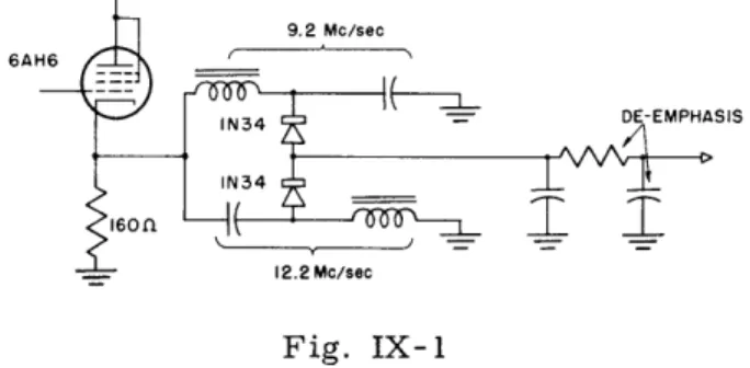
A slight modification of the wide-band detector discussed in Technical Report No. 42,
by J. Granlund produces the circuit shown in Fig. IX-1. Notice that the cathode supplies
the bias needed for the crystals.
R. A. Paananen
The design of a tuning head for a frequency modulation broadcast receiver has been
brought to the working-model point. Using variable capacitor tuning, and a single stage
of tuned radiofrequency amplification, all spurious responses are down at least
80 db (for interfering signals below 0. 4 volt) and the sensitivity is comparable to usual
commercially available receivers.
At a slight sacrifice in spurious response rejection,
sensitivities can be improved by increasing the couplings in the input tuned circuits.
Noise figures as low as 6 db have been measured, in the latter case.
H. H. Cross
The effect of discriminator bandwidth on adjacent and alternate channel interference
is under investigation.
B. STATISTICAL THEORY OF COMMUNICATION Prof. J. B. Wiesner Prof. W. B. Davenport, Jr. Prof. R. M. Fano Prof. Y. W. Lee Prof. J. F. Reintjes Dr. P. Elias
B. A. Basore
R. S. Berg
J. J. Bussgang
M. Coufleau
C. A. Desoer
L.
Dolansky
B. M. Eisenstadt
E. Green, Jr.
Howland
G. Kraft
A. J. Lephakis R. M. Lerner M. J. Levin1. Multichannel Analog Electronic Correlator
A suitable integrating circuit has been developed.
The remainder of the design work
for the correlator has been completed.
Testing of the equipment is proceeding.
Y. W. Lee, J. F. Reintjes, M. J. Levin
2. Analog Electronic Correlator for Second-Order Correlation
The second-order autocorrelation function of a random or periodic function fl(t) is
defined as
f
fl(t) fl(t
-T
+ T1) fl(t + T
2)
dt.
Equipment is not yet available for plotting this function.
However, if T
1 =0
111( 0 , T2)
= lim
T-oo
f
(t) f(t + T) dt.For this special case the second-order autocorrelation function can be obtained by
crosscorrelating f (t) with fl(t). This hasELECTRONIC ANALOG CORRELATOR QU A CHANNEL CIRCUIT B CHANNEL f(t) Fig. IX-2
Arrangement for obtaining second-order autocorrelation functions.
been done as shown in Fig. IX-2.
LADDER NETWORK Fig. IX-3
Squaring circuit.
1
111(
T1)
) = lim
T--oo(2)
(IX. COMMUNICATION RESEARCH)
The squaring circuit(J. S. Rochefort: "Design and Construction of a Germanium-Diode
Square-Law Device, " Master's Thesis in Electrical Engineering, M.I.T. 1951) makes
use of the nonlinear properties of 1N34 germanium diodes (see Fig. IX-3).
A
two-terminal ladder network composed of resistors and these diodes has been constructed.
This network has a variable driving-point impedance such that the current through it
is proportional to the square of the voltage across it.
The voltage across a small
resistor in series with the network is then proportional to the square of the input voltage.
The sign of the output should be positive whether the input is positive or negative for
proper square-law action. This characteristic is obtained by using a push-pull driver
circuit.
Since the driver circuit works into a varying impedance it was designed to
have a very low output impedance for accurate operation. Appreciation is expressed
to Mr. Rochefort for providing the necessary information for the design of this unit.
If the function fl(t) in Eq. 1 is periodic and has the spectrum Fl(n) with the
funda-mental angular frequency wl, so that
oo00
f (t) =
F
1(n) e
(3)
n= -c
it can be shown that the second-order autocorrelation function of fl(t) is
o00
0m
j(m+n)wl(Tl
+ T2)
111(T2) =21 F1(m) Fl(n) F 1(m+n) e
m=-oo n=-oo
For the particular case where fl(t) is an odd-harmonic function, 111(T 1 , T2) vanishes for all values of T1 and 72 since Fl(m+n) is zero.
Figure IX-4b shows the autocorrelation function of the half-wave rectified sinusoid
which is illustrated in Fig. IX-4a. Figure IX-4c shows the second-order
autocorrela-tion funcautocorrela-tion of this wave.
For a wave of the form shown in Fig. IX-5a, the
auto-correlation function and the second-order autoauto-correlation function are given in
Figs. IX-5b and IX-5c respectively.
Y. W. Lee, J. F. Reintjes, M. J. Levin
3.
Information Theory
a. Transmission of information through channels in cascade
Further investigation of this problem has indicated that the operation of the
inter-mediate receivers is the important factor in the performance of the over-all system.
For example, in the pulse code modulation system analyzed previously the receiver
requantizes the received pulses. This requantization process eliminates the noise in
almost all instances although errors are introduced once in a while.
(A relatively
Half -wave rectified sinusoid. Fig. IX-4b Autocorrelation of waveform in Fig. IX-4a. Fig. IX-4c Second-order autocorrelation of waveform in Fig. IX -4a.
Triangular wave with odd harmonic function.
Fig. IX-Sb
Autocorrelation of waveform in Fig. IX-Sa.
Fig. IX-Sc
Second -order autocorrelation of waveform in Fig. IX-Sa.
General data pertaining to curves: AT
=
5 IJ.sec; number of samples=
8000;Fig. IX-6
E as in Eve.
Fig.
IX-8
S as in Hiss.
Fig. IX-lO
Z as in Craze.
Fig. IX-7
U as in Boot.
Fig. IX-9
F as in Gaff.
Fig. IX-II
A as in Father.
high S/N is assumed.) The introduction of definite errors can be shown to result in additional loss of information; it appears that any attempt to eliminate a fraction of the noise necessarily involves an additional loss of information. On the other hand, if some of the noise contained in the signal is eliminated, the fraction of information lost in the next transmission is reduced. It appears therefore that there is some optimum degree of noise elimination. In the above case the over-all system is improved by quantization, at the intermediate stations, to the original levels, although in some cases quantization to a larger number of levels may be better. The question of noise elimination is the main problem under study.
C. A. Desoer, R. M. Fano
b. Vocoder
The possibilities of a high quality vocoder are being investigated using, initially, the approach of tracking the harmonics of pitch frequency (1). This and related
tech-niques are critically dependent upon an accurate knowledge of the pitch period of voiced sounds. Previously used methods of obtaining the pitch period appear unsatisfactory for our purposes. We are currently investigating the use, in this connection, of the
"Ianalytic function" (2) of speech. The analytic function of a speech wave is a complex function of time. Its real part is the speech wave itself, and its imaginary part is the same speech wave in which each frequency component has been shifted in phase by 90.0
To this end, a wideband (50 cps to 15, 000 cps) phase-splitter has been constructed. When the outputs of the phase-splitter are connected to the vertical and horizontal deflection plates, respectively, of an oscilloscope, patterns result which constitute a polar representation of the analytic function.
As a by-product of the above work, such polar patterns may be useful as a new form of visible speech. Several patterns are shown in Figs. IX-6 through IX- 11. In addition to the static characteristics that may be observed in these photographs, dynamic
char-acteristics have been observed which might play an important role in the visual identi-fication of speech sounds.
Possible uses for this method of representation are being investigated.
R. M. Lerner, R. M. Fano
References
1. R. M. Fano: The Information Point of View in Speech Communication, J. Acous. Soc. Am. 22, No. 6, 694-695, 1950
(IX. COMMUNICATION RESEARCH)
C. HUMAN COMMUNICATION SYSTEMS
Dr. L. S. Christie J. B. Flannery D. G. Senft
Dr. R. D. Luce J. Macy, Jr. A. G. Simmel
F. D. Barrett P. F. Thorlakson
1. Technical Report
Our major project during the past quarter has been the preparation of a technical report summarizing the results and developments of the past two years. The report will describe the 1949-1950 experiments of Professor A. Bavelas and associates, who first explored the problem area of task-oriented groups. The work of the past year, involving a more intensive study of a restricted part of the problem area and employing more refined experimental techniques, will also be described.
The principal experimental program (1) has been concluded. The primary purpose of this program was to examine learning within a task-oriented group. The results shed light on earlier work of Leavitt and Smith. Considerable time has been spent on the complex data analysis required. This analysis will be concluded during the next quarter. The principal development in experimental technique, "Octopus", is reported briefly below and will be discussed in full in the forthcoming report.
F. D. Barrett, L. S. Christie, R. D. Luce, J. Macy, Jr.
2. A Problem in Data Analysis: Programming for Whirlwind I
For the analysis of the data from experiments on network patterns and group learning (1) it is necessary to have the distributions of the number of time units, i. e. opportunities to send a message, required to distribute all the relevant information to
all the members of the group, assuming equilikelihood for the use of the different channels going out from any individual.
For many networks this problem appears sufficiently complicated mathematically to warrant a quasi-empirical approach by means of random numbers and the use of high-speed computing machinery. Whirlwind I was made available for this work, and a code has been developed which is of sufficient generality to permit adjustment to different networks by very simple modifications. If it should become of interest to investigate n-man groups, n 4 10, or to make some assumptions other than equilikelihood for the use of the different channels going out from the individuals in the group, the completed code may serve as a core around which such modifications can be constructed.
We define matrices S such that s.. = 1 or 0 according as individual j has or has not the information originally possessed by individual i, and matrices T such that tij = 1 or
0 according as individual i is sending all the information at his disposal to individual j or to someone else, letting the diagonal terms be unity in the matrices of both types.
If we further let I be the identity matrix I 18ij I and E the universal matrix Ieij I,e
having e.. = 1 for all i and j, we may state our problem as follows. Given
S =I (1)
S = S T (2)
n
n-l n
where the product in Eq. 2 is the Boolean matrix product defined in strict analogy to the ordinary matrix product by
S' = ST if and only if n SU = (ik
)
tkj) k=lWe want to know the distribution of N where SN = E and for all n < N, S E.
The Whirlwind I program constructs the T-matrices as needed by means of random digits fed from a tape into the high-speed storage in blocks of 375, guided by a set of 5 control numbers peculiar to the network under investigation. The distribution of the values of N < 10 will be typed out.
Testing of the program is under way.
A. G. Simmel
3. "Octopus"
The electrical experimental device (2), nicknamed "Octopus, " for running controlled experimental groups of human subjects, has been partially completed. The individual stations for the subjects and the central control unit have been completed and tested, and preliminary trials using military subjects have been successfully completed. Con-struction of the component parts of the automatic data-recording and analyzing unit has been finished, and final assembly and testing of this unit is nearing completion. The tape-recording device, using binary sequences time-multiplexed on punched magnetic recording tape, has been completed. Future experiments employing Octopus are in the planning stage.
J. Macy, Jr.
4. Experiment on the Persistence of Organization
In conjunction with Harvey Hay, graduate student in the Department of Economics, M. I. T., an experiment has been designed to detect the persistence of inappropriate voluntary organization within a task-oriented group. The question being asked is: Given a group having a simple task to perform and communication by written messages
(IX. COMMUNICATION RESEARCH)
network to another ? It has been found in earlier experiments of a similar type that
under certain networks, groups develop an internal organization which is appropriate
to that network. Does such an informal organization persist in a new network, or does
it decay as rapidly as it is formed, when it is no longer appropriate? Further, does
the experience and consequent learning of the first network tend to affect adversely
learning in the second network?
For any group of subjects the experiment will have three phases. Five trials will
be performed on a network which we shall call P. Following these, a questionnaire
will be administered. After a break for lunch, two sets of 15 trials each will be run
on different networks, each followed by the same questionnaire as used after P. Our
interest is only in the last two phases.
The network P is run in order to eliminate a
transient phase of confusion and adjustment to the apparatus. P was chosen to be a
network within which very little organization can occur in five trials. The questionnaire
is also used after P so that the subjects will have the same knowledge as to the content
of the questionnaire when entering phase two as when entering phase three. In addition
to P, there will be three networks used in the afternoon sessions: circle C, star S,
and diablo D.
The combinations to be run are PPC, PPD, PSC, PSD, PDC, PCD.
10 groups will be run in each combination.
The apparatus to be used for this experiment is a modification of that described in
reference 1; and, in particular, includes the important feature that all communication
occurs in a quantized time scale. This, or something equivalent to it, is necessary for
the determination of the time order of the messages sent.
The subjects to be used are enlisted Army personnel.
L. S. Christie, R. D. Luce, J. Macy, Jr.
References
1. Quarterly Progress Report, Research Laboratory of Electronics, M. I. T. Jan. 15,
1951, pp. 79-80
2.
Quarterly Progress Report, Research Laboratory of Electronics, M. I. T. April 15,
1951, p. 52
D. REPLACEMENT OF VISUAL SENSE IN TASK OF OBSTACLE AVOIDANCE
Dr. C. M. Witcher E. Ruiz de Luzuriaga
A small project has been set up in the Laboratory; its object is to extend the field of sensory replacement to the visual domain as specifically applied to the problem of independent travel by the blind. Analysis of the performance of all obstacle avoidance devices developed to date strongly suggests that their major failing has been a result of inadequate means for transmission of information from device to user. In all schemes thus far employed the information was transmitted to the user as a time series of data; each element provided information as to the presence or absence of an obstacle in some small specified portion of the environment. Thus the necessary integration always had to be done within the brain of the user.
The present aim of our project is to devise a method of transmission of information from guidance device to user in which part of the integration process can be taken over by the device, enabling a much needed increase of speed in the process and affording a
decrease in the mental effort which must be expended by the user.
We have started from the obstacle avoidance device developed a few years ago by the Signal Corps, and which appears to be the most reliable and satisfactory type available at present. Our proposed solution to the problem of providing integrated information consists of two modifications of this device: 1) addition of an automatic optical scanning system, and 2) presentation of the information through the presence or absence of projecting points, or, more precisely, round-headed pins, at various posi-tions on a signal presentation plate. The positions of the pins, which at any moment project above the surface of the signal presentation plate, can be quickly surveyed by very slight movements of the index finger of the blind user, and he can thus obtain an almost instantaneous, if rather crude, picture of the obstacles in his immediate envi-ronment. The positions (radial and angular) at which pins appear on the plate will correspond roughly to the positions of the obstacles in range and azimuth, much like the situation represented by a PPI radar presentation. The moving pins will be actuated by relays fed from the output of the small hearing-aid amplifier of the device. The mechanical design of the system is now fairly complete, and the circuits for relay operation have been checked experimentally.
In addition to this system for presentation of information, a tentative design for a step-down indicator, an element which has long been recognized as a necessity for safe travel, has been completed.
(IX. COMMUNICATION RESEARCH)
E. COMMUNICATIONS BIOPHYSICS
Prof. W. A. Rosenblith K. Putter
1. Interaction of Cortical Activity and Evoked Potentials
Sizable responses to clicks are recorded from the auditory area of the cerebral cortex of anesthetized animals. The present study proposes to investigate systemati-cally the extent to which these evoked responses modify cortical activity and are in turn affected by this activity. Preliminary experimentation has been started at the
Massachusetts General Hospital. The use of correlational techniques for purposes of data analysis is projected.
W. A. Rosenblith with Dr. M. A. B. Brazier (Massachusetts General Hospital) 2. Variability of Cortical Responses to Acoustic Clicks
Responses to clicks recorded by fine wire electrodes from the auditory area of the cortex of anesthetized animals are characterized by large variability. If a theoretical useful quantitative description of such responses is to be given, reliable data on cortical variability are essential.
A large number of responses have been recorded simultaneously from two locations of a cat's auditory cortex; the rate of stimulation was varied from 2 clicks per second to 1 click every 10 seconds. The data are being analyzed by different statistical techniques in order to determine the character of the observed variability. If the variability is non-random, an attempt will be made to differentiate between response-induced nonrandom-ness and nonrandomnonrandom-ness due to physiological periodicities (e. g. cortical rhythms).
The experiments were carried out at the Psycho-Acoustic Laboratory, Harvard University.
W. A. Rosenblith, K. Putter, with K. Safford (Harvard Psycho-Acoustic Laboratory) 3. Instrumentation
A useful device for the analysis and presentation of electrophysiological data recorded in response to discrete stimuli might have the following properties: a) it would take "peeks" of adjustable duration at preset intervals after the occurrence of the stimulus; b) it would quantize the evoked response at the highest level reached during the "peeking-interval; " and c) it would present the central tendency and the variance of the quantized data and also record the data in sequential form.
A preliminary model of such a time-gated amplitude quantizer having most of the enumerated features is now in the design stage.
F.
ELECTRONEUROPHYSIOLOGY
J. Y. Lettvin
W. Pitts
B. Howland
With the design and building of two constant-current stimulators, a machine that
manufactures the numerous microelectrodes used in our experiments and an elaborate
control device for programming whole experiments, an electrophysiological laboratory
is being set up.
The shop is now working on the design and construction of a new
stereo-tactic instrument.
We have been applying a constant input-volley to the spinal cord, and plotting the
potential field and its changes with time at as dense a network of recording points within
the cord as is practicable.
Since the cord is narrow and a good conductor, the potential
at each point is determined by an integration over all the sources and sinks of current
in the entire cross section; and the more remote suffer only a small decrement with
distance.
These sources and sinks represent the activity of cells and fibers where they
are, for flow of current from the inside of a cell outward makes a source in the
exter-nal medium in which we measure; current inward makes a sink.
The density of these
sources and sinks can be calculated by taking the Laplacian of the potential; the
com-puting room has been doing this for us numerically from the potential maps derived from
earlier experiments.
The result is a series of maps representing the successive
acti-vity of different groups of cells or fibers. From these maps we hope to find out how the
groups of cells combine to produce the complicated structure of the spinal reflex, and
how the transmission of information to them along pathways descending from the brain
so modifies the structure as to control movement.
To this end we plan first to complete
our analysis of the sequence of maps of sources and sinks produced by various inputs to
the isolated cord, then to note the differences when certain of the most important
descending systems are stimulated concurrently. Somewhat aside from this, we expect
these maps to contribute crucial evidence for or against our earlier theory of inhibition
at the synapse.
// We plan to apply the same methods, combined with various forms of statistical
anal-ysis, to a study of some of the higher sensory systems, such as the visual cortex and
lateral geniculate, from the point of view of communication theory. To record the
potentials from one or a few points on the surface of the cortex, as has been usually
done, does not, in our opinion, furnish suitable material for such an analysis; for we
This section has been supported in part by the Department of the Navy, Office of Naval
Research, under Contract No. N5 ori-07868. Authority: NR 113-004/9-6-51,
Bio-logical Sciences Division.
(IX. COMMUNICATION RESEARCH)
cannot ordinarily discover which of the numerous groups of cells and fibers, distinct in
function and connections, are responsible for the potentials recorded. But the two
methods: that of measuring potential histories at enough points to compute sources and
sinks, localizing the generators of the potentials; and the statistical methods of
com-munication theory, should provide more information about the system, and better means
of analyzing it.G. PARALLEL CHAIN AMPLIFIER
The behavior of the high frequency amplifier chain of a parallel chain amplifier has been reported in the Quarterly Progress Report, October 15, 1951. An average gain of about 5 db per stage was obtained over a band from 130 to 260 Mc/sec using 6AK5's with double-tuned interstages.
An input circuit for this chain has been tried. The results are mentioned here only as they give an idea of the problem of network complexity when dealing with small shunt capacitances. It will be shown that the use of this input circuit should have considerably improved the gain of the chain. Instead it was found that the gain was slightly reduced. The poor results are probably due to stray capacitances disturbing the network struc-ture.
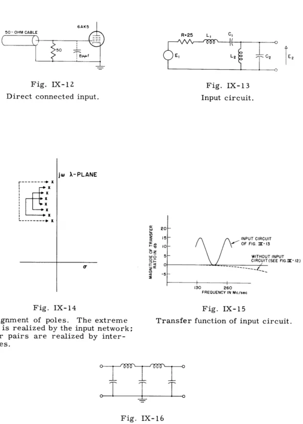
The input capacitance of the first stage is about 8 p.aif. The input is fed from a terminated 50-ohm cable, which provides a 25-ohm source. Originally, the cable was connected directly to the grid as shown in Fig. IX-12. The input circuit tried is shown in Fig. IX-13, where the source is represented by its Thevenin equivalent. Here R = 25 ohms and C2 = 8 pif, and the products LIC1 and L2C2 are equated to make this circuit the bandpass equivalent of a simple series LC circuit.
If R is temporarily assumed zero, the poles of the transfer ratio, E2/E 1, will occur on the jw axis, say at wI and w2. Then, if we solve for the element values we find
1
2 1
C = C
1 212
(3)
1l W2
Returning to the lossy case, R * 0, we may conveniently express the transfer ratio in terms of the critical frequencies of the lossless case, w1 and w2 , and also R and C2
E2 (2 ,1 2 2 2
=4 Z 3 2 2 ) . (4)
1
+
RC 2(o 2 - 1 X + (2 1) + RC 2W12 2 11+ X
1We may now quickly evaluate the contribution of the input network over the band for a simple but representative case.
6AK5 50- OHM CABLE
Fig. IX-12
Direct connected input.0
X
--- * X L .. ... Fig. IX-13 Input circuit. jw X-PLANE a, INPUT CIRCUIT OF FIG. I- 13 WITHOUT INPUT CIRCUIT (SEE FIG.I- 12)- /
130 260 FREOUENCY IN Mc/sec
Fig. IX-14
Assignment of poles. The extreme pair is realized by the input network; other pairs are realized by
inter-stages.
Fig. IX-15
Transfer function of input circuit.
.
T
T.
Fig. IX-16
An interstage used in the
low frequency chain.
First we notice that the multiplying factor of the transfer ratio is (W -
1
) 2.
To aid in selecting two poles from the whole array of poles of the over-all transfer
function, we also consider the multiplying factors of the interstage networks used in
this chain. These multiplying factors are equal to (
b-
wo)/2C
where the w's refer to
the critical frequencies of a particular interstage and C is the shunt capacitance
imposed at each terminal pair. We maximize the over-all multiplying factor, which is
just the product of the individual multiplying factors, by pairing the poles as shown in
Fig. IX-14.
This maximization gives the greatest spread for the poles of the input
network and equal spread for the poles of the interstages. For this arrangement C
1turns out to be about 5
p.Lff.For expediency, let us set wl and w
2equal to the upper and lower edges of our band
(corresponding to 130 and 260 Mc/sec).
The magnitude of the transfer ratio at the band
edges is, from Eq. 4, equal to 1/[RC
2(
2- w1)
=
6. 1 (ratio) or 15. 7 db. Similarly, at
the geometrical band center, this ratio is identically one or zero db.
In Fig. IX-15
these values are used to sketch the approximate transfer ratio over the band. The
transfer ratio of Fig. IX-12 is also sketched for comparison.
(Of course, with the
addition of the input network, the interstages are appropriately realigned. ) Thus we
see that the input network should result in an over-all improvement of gain.
The low frequency chain has been built, but the alignment has not been completed.
After some delay, a setup was obtained to measure the gain over this band
(0-130 Mc/sec).
Also, a generator to sweep the entire band (0-260 Mc/sec) for
align-ment purposes has been built, using a thermally-tuned klystron.
After the gain measuring equipment was set up and a calibration run taken, a
pre-liminary run was made on the gain. This run showed serious attenuation between
120 Mc/sec and 130 Mc/sec.
The trouble was traced to a self-resonance of series
coils in two circuits of the type shown in Fig. IX-16.
Although some care had been
taken to keep the distributed capacitance of these coils small, they were found to
reso-nate in the affected region, producing zeros there.
The coils are being rewound, and
it is expected that the new coils will remedy this trouble.
R. K. Bennett
H.
A METHOD OF WIENER IN A NONLINEAR CIRCUIT
Technical Report No. 217 has been prepared and has been scheduled for publication.
S. Ikehara
(IX. COMMUNICATION RESEARCH)
I. TRANSIENT PROBLEMS
Prof. E. A. Guillemin Dr. M. V. Cerrillo F. Reza
1. Network Synthesis for Prescribed Transient Response
A given transient time function f(t) is to be the unit impulse response of a finite passive lumped-parameter network. The problem is to find the pertinent system function h(s) of this network.
If, for the moment, one were to consider a periodic time function f(t), the desired system function could be found at once from a Fourier series representation for f(t); and the requirement that the system function be rational could be met through being content with the approximation to f(t) afforded by a partial sum. A study of the nature of this approximation could be dealt with in the time domain according to familiar techniques; and since no further approximations in the frequency domain were called for, the ultimate response would be assured of having the approximation properties of the partial sum.
One way of dealing with a given transient function f(t) of finite duration is to con-sider its periodic repetition in several ways such that an appropriate combination of the resulting periodic functions cancels everywhere except over the first period. A
simple pattern accomplishing this end is described in the following.
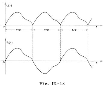
Suppose a desired f(t) is the transient pulse shown in Fig. IX-17. We consider the two periodic repetitions of this function as shown in Fig. IX- 18 and observe that the corresponding transforms hl(s) and h2(s) are readily constructible from the appropriate Fourier series for fl(t) and f2(t). If we could synthesize a pair of two-terminal net-works N1 and N2 having the driving-point functions hl(s) and h2(s), it is clear that their unit impulse responses would be fl(t) and f2(t) respectively. Or we can say that if we were to apply an excitation fl(t) to N1 or an excitation f2(t) to N2, the response in each
case would be a unit impulse. If we now observe that
and
f(t) = f2 (t) t -
)
(2)we can conclude that if we apply an excitation f(t) to N1 the response is a unit impulse at t = 0 followed by a negative unit impulse at t = T/2; while if we apply an excita-tion f(t) to N2 the response is a unit impulse at t = 0 followed by another at t = T/2.
Therefore, f(t) applied to N1 and N2 in series produces simply an impulse at t = 0, or the latter produces f(t), which is what we wanted. It remains to fill in the details with appropriate mathematical symbols.
We begin by considering the periodic function f p(t) shown in Fig. IX- 19, consisting of a repetition of f(t) at half-period intervals. Writing the Fourier series
f (t) = E akejkt
k=- oo
we have for its transform
h (s) ak p(s)
hp(S) s - jkw q( " k=-oo
(4)
The transforms hl(s) and h2(s) are readily constructible from h (s).
p
hl(s) = hp (s) oo ak(1 +e-Jk)
s - jkwand
00 a_(1 - e- j k w I-.a h2(s) = h (s)Noting that the factor (1 + e- j kw) factor (1 - e-jkw) equals 2 for k
(1 - e- ST/) K'
-00
equals 2 for k even and zero for k odd, while the odd and zero for k even, we have more simply
hl(s) = 2 k=0+(2,4, .. ) oo k=+(1, 3 ... .)
and
h2(s) = 2Fig. IX-17
The desired transient time function.
ak P1(s)
s-jk
ql(s)
ak P2(s)-jk
S
(7) (8)That is to say, hl(s) is twice the sum of the even order terms in h p(s), given by Eq. 4, while h2(s) is twice the sum of the odd order terms.
As long as the sums in the expressions for hp(s), hi(s) and h2(s) are regarded as having an infinite number of terms, these transforms are, of course, not rational and the polynomials
Fig. IX-18
The auxiliary periodic repetitions of f(t).
fp(t)
- T/2 T r/2 - ./2
Fig. IX-19
The basic periodic repetition of f(t) from
which the auxiliary functions of Fig. IX-18
are derived.
fp*(t) I I f*(t-r/2)+A f(t) af(t) ,.~~~- "1. III v. . -I I I A f IFig. IX-20
Approximation to the periodic function of
Fig. IX-19 afforded by a partial sum of its
Fourier series, and the imperfectly delayed
version of this function.
O II % #
1
ir\
/'""
-
rj
p(s), q(s), p1(s), q1(s), pZ(s) and q2(s) are not finite. Since we anticipate replacing these expressions by their partial sums, it is appropriate even at this stage to think of the polynomials as though they were finite. They obviously have real coefficients even though the Fourier coefficients ak (which are residues of the h functions in their j axis poles) are complex.
If we think of networks N1 and N2 as having the driving-point functions hl(s) and h2(s), then a unit impulse u (t) applied to N1 produces fl(t) and if applied to N2, it produces f2(t). If we now interchange the roles of excitation and response, and say that fl(t) applied to N1 or f2(t) applied to N2 produces u (t), then the system functions for these networks are the reciprocals 1/hl(s) and 1/h 2(s). Noting Eqs. 1 and 2 we may then state that f(t) applied to N1 having the system function 1/hl(s) produces the response
uo(t) - u 0(t -) (9)
while f(t) applied to N2 having the system function 1/h 2(s) produces the response
u (t) + u
0(t
-
).
(10)
Wherefore, f(t) applied to N1 and N2 in series with the resultant system function (1/hl) + (1/h 2) produces the response 2uo(t); or if we again interchange the roles of excitation and response and consider the series combination of N1 and N2 as having the
system function
1
1
2
then its unit impulse response becomes (1/2) f(t), as may readily be verified through substitution of Eqs. 5 and 6 into Eq. 11, which yields
1 S
P(s)
" P2(s)h(s) = h p(s) (1 - e-s 2p(s) " (12)
Since the time-domain equivalent of this equation reads
f(t) = (f (t) - f(t-T)) (13)
the above statement is seen to be true.
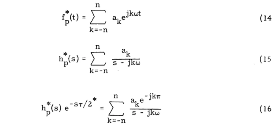
Neglecting second-order effects, it is easy to show that when one replaces the above infinite series by their partial sums, the resulting transient response is as good an approximation to f(t) as the partial sum of the Fourier series given in Eq. 3 is to f p(t) over any one of its periods. Thus, if we indicate any approximate function through attaching an asterisk to the corresponding exact function, we may write
(IX. COMMUNICATION RESEARCH)
n
f (t) =
)
akeJt
(14)
k=-n
n
ah(s)
=k
(15)
h
p
(s) s -jkwk=-n
and
n -jk*
h
(s) e-ST/2* ake (16)p
s - jko
(16)
k=-n
where n is a finite integer.
Figure IX-20 shows how the approximation to f p(t) given by the partial sum (Eq. 14)
might look, and correspondingly how the inverse transform of the frequency function
(Eq. 16) will appear. It is important to note that this time function may be regarded
as an imperfect version of f (t) delayed by a half period. Thus, the perfect version of
f (t) delayed by a half period differs from the function shown in the bottom half of
Fig. IX-20 in that it is exactly zero throughout the first half period. The imperfect
version, by contrast, has the same nonzero ripply variations here that it has in any of
the corresponding subsequent half-period intervals. Observe, however, that the
imper-fect and perimper-fect versions are exactly alike everywhere except during the first half period
where they differ by the residual ripple which in Fig. IX-20 is denoted by Af(t). That
is to say, the net difference Af(t) between the imperfectly and the perfectly delayed
functions f (t) is nonzero only for the interval 0 < t <
7/2!
p
In the frequency domain we can express this result through writing
h
(s)e-/
2h (s) e- r/2+ Ah(s) (17)
p
p
and interpreting Ah(s) as a frequency function whose inverse transform is Af(t) and
hence is nonzero only for 0 < t <
7/2
where it amounts to a small ripple. From Eq. 17
we may now form
- s r/ 2 - s / 2
h(18)
e
e
+(18)
h
p
Through squaring and neglecting the term involving (Ah)
2 ,we have
-
ST
ST*=e -S-+
-
2h
2AheT/
-
sr/2(19)
h
p
whereupon the pertinent relation (Eq.
12) becomes
h
*(s) =h
(s) (1 - e- *) =h
(s) (1 - e-T) - Ahe- s r / 2 (20)7
p
7 P20
and the corresponding time function is
f(t)
= (fp(t) - fp(t-) -Af(t
- . (21)The first term in this last expression equals one-half the function f*(t) for the
* p
interval 0 < t < T and is zero otherwise. The second term is f (t) for
7/2
< t < T with Pits sign changed. The result (except for a factor of 1/2) equals f (t) for 0 < t < '/2, -f (t) for T/2 < t < T, and is zero otherwise.
p
The second-order effects, which have been neglected, will slightly alter the form of f*(t) during the interval 0 < t < T, and will prolong the error in an asymptotically decreasing fashion thereafter.
The method of finding a system function appropriate to a desired transient pulse of arbitrary shape as discussed in the above paragraphs is the logical generalization of a method used during the war for designing networks to produce rectangular radar pulses. It took the writer approximately ten years to stumble upon this generalization.
E. A. Guillemin
2. Basic Existence Theorems
Section 1
A New Integral Representation of Laplace Transforms
1. 0 A set of new integral expressions for the representation of direct and inverse Laplace transformations will be presented first. These integral expressions are the basic tool for proving a set of existence theorems for fundamental problems in the theory of network synthesis. Several existence theorems are presented in this report.
1.1 Let
f(t) = f 0 for t > 0, and such that
If(t)I
< Mect (1) 0 for t < 0where M and c are finite positive constants. Let co , the abscissa of convergence, be the lowest bound of c which satisfies this inequality. Then, as is well known, f(t) is Laplace transformable. Its transform F(s) is analytic in the right half of the s plane beyond the line parallel to the w axis and at a distance co from it.
The direct and inverse Laplace transformations are given, respectively, by the integrals
(IX.
COMMUNICATION RESEARCH)
00F(s) = f(t) e
- s tdt
0
f(t) = I JF(s) est dsfT17
1d
s + iwwhere r is a line going from -ioo to ioo such that all the singularities of F(s) lie to the
left of
F.
1.2 For the purpose of our representation we shall select
F
as a symmetric curve,
having the branches
F
and F'.
F'
is the image of
F
with respect to the real axis, as
shown in Fig. IX-21. An arbitrary point of the s plane will be denoted by
s =
cr
+ iW
(3)
For points on the contour
Ewe
shall use, for convenience, the notation
S = y + iX
(4)
Finally, the analytic expression for 1 is
(y,
) = 0
(5)
A simple algebraic process shows that the second integral in (2) can be expressed
by an integral along
F
only,
1
f(t)
=
f
from which we obtain the form
f(t) =
±
eyt U(y,k) [sin Xt dy +F-F(S) eSt dS - F(S) et dS Zi
cos Xt dX
+V(y,k) [cos Xt dy
- sinXt dX]
(7)
in which
F(s)
=
U(o-,
) + iV(cr, w)
F(S) = U(y,X)+ iV(y, X)
(8)
1.3 Let us indicate by I the distance from the point P to yo along the curve T as
indicated in Fig. IX-22.
From Eq. (5) we get
ad
a d X=
- dy + - d = 0
(9)
The contour P is defined by the function €(y, X) 0.
Fig. IX-22
The contour
I,
the coordinate I and the direction cosines of
d.
s PLANE
Fig. IX-23
The contour r.
(IX. COMMUNICATION RESEARCH)
cos 0(y,X)
=sin
(y, x) =
dya
)2
2~
2a
(
)
D
(10)
A few algebraic manipulations lead to
f(t) = f e IF(y, k) sin
[Xt
+ (y, ) + (y, )] dcUF(S)
=
IF(y,X)
I
ei(y,
X)
'1.4 We shall now obtain the corresponding expression for F(s).
F(s) = 0
(11)
(12)
Since
f(t) est dt
then one can multiply (7) by (e
s tdt) and integrate between zero and infinity.
By
reversing the order of integration (which is justified here because r is to the right of
the singularities of F(s)), and considering the integrals
e-st e sin t
X
(s-y) 2 +
2
s-y)(s-y) +
x
(13)
one gets
F(s) = IfU(y,X) [Xdy + (s-y) d + V(y,k ) [(s-y) dy - dk]
By introducing the functions defined by
s - - =
(s-y) +
(s-y) +
x
1(s-y) + X
cos K(s, y, k)
sin K(s, y, X)
in which
(14)
(15)
one gets
F(s) = F(y,X) sin K(s,, y,) +(y,)+ (y) d (16)
1.5 The expressions for f(t) and F(s) of a strategic contour are very useful in proving
the final forms at which we are aiming.
They also play a basic role in later theorems.
The new contour is the semi-infinite line obtained by setting y = -o
=
constant > c .
See Fig. IX-23.
This particular contour will be designated by 0
The corresponding integrals follow by setting dy
=
0, or 0
=
w/2, and
dX = dl. They
are
yt
f(t)
=
e
1
U(Y
o ,) cos
Xt
- V(Yo,
) sin
Xt
dX
o
(17)
= e- IF(yO, X)I
cos [Xt + (yo,k) dXP
(s
-
) + X
(18)
=
IF(
,X)I
cos[K(so,
k) + P(,)
dX
r
o1. 6 Our aim is to produce two final sets of basic integral representations.
The first
of these sets reads
2 r vt..
rf (t)
=-
e'
U(y, ) Lcos Xt dX +
sin
Xt dYjI
r
=2f
eYtU(y,X) [sinXt + 0(y ,)]
Cd
7
F(s)
=
j
Xdy + (s-y) d)
U
)
S(s-y)
2
+X
=
.sin
K(s,
y, )
6(y,
)1
U(y,
k) d~i
(19)
Iwhich
both f(t) and F(s) in terms of the real part of F(s)
permits us to express
which permits us to express both f(t) and F(s) in terms of the real part of F(s)
(IX. COMMUNICATION RESEARCH)
along the contour F.
A direct proof of (19) is rather long for this report. Instead, we shall first furnish
a simplified (and correct) proof, valid for the particular contour F o . The passage fromF
to F is not difficult.0
1.7 The proof for
Fo
follows with ease by introducing Hilbert transforms. (See, for example, E. A. Guillemin: "' The Mathematics of Circuit Analysis, " John Wiley, New York 1949, pp. 330-349.)Let f(z) = U(x,y) + iV(x, y), z = x + iy. The transforms are given by
+00
U(x,
y) =-f
xU(o, d Tx0) x 2+
(y-
n)
+00
V(x,y) = -f (y- ) U(0,
d
-00
(20)
To apply them to our case we F0 + F'. We obtain
0
set x = y - yo, y = X, and designate by 0 the contour
U(y, X) = - Y) U(Y, d
S(V
-Vo) + (X-)
Fo
V(y,) = - (_ -YO)2 ( 2 d_)1
'T
-
(y
-y
0+
(X-Tl)
10
/
where yo > c
o.
Substituting these expressions in (7) and
gration (justified by the condition yo > c ) one gets
1
f(t)
= U(yo,1) d f et U(y,X) (sinF I r0
inverting the order of
inte-Xt dy + + V1(Y, X) (cos Xt dy
-cos
Xt
dX)
sin
Xt
dk
where
Y - ¥o U(Y,X ) =V
(V
-YO)
2+(X-q)
(22)
V(Y,X)
=-(
(X-
n)
(V -
,)2 + (×-hi
(21)
(21a)
One recognizes immediately that expressions (22) are, imaginary parts of the function
F
1(S) = s - (y0 + in) =respectively, the real and
(23)
The corresponding time function, say fl(t), is
S
0t
fl(t) =
e +(o +i)tfor t < 0
(24)
for t > 0
Now, expression (7) reveals immediately that the bracket parenthesis of (21a) is exactly the function fl(t). Consequently, Eq. (21a) becomes
f(t) =
(y +iq)t
U(y
0,
)e
dq = e T U(y , 0 ) cosit + i sin t] d' for t >, 0
(25)
Finally, recalling that U(y
0, 1) (in
one gets, by changing 9 to X
for t < 0
Laplace transforms) is necessarily an even function,
S2e U(y ,
k)
cosX t d for t > 0r
f(t) =
0 fort <0
where yo > c . By the direct Laplace transformation of (26) we get
2(s -Yo
)
F(s) = ITU(o, X) dX
(s - o) +Xfor yo > co
(26)
(27)
. L(IX. COMMUNICATION RESEARCH)
Therefore, expressions (26) and (27) show the veracity of (19), at least for =
0o
1.8 Expressions (26) and (27) produce both f(t) and F(s) in terms of a generic function U(Y0o , ) for F = o . These expressions can be solved for U(a, o).From the first integral in (2) one gets
F(s)
=
U(cr,
)
+ iV(a,wo)=
f(t) e
-3
t(cos ot
-
i sin ot) dt
from which
U(cr, w)
=
Je
- tcos
wt f(t) dt
0
0oU(Yo,
X)
=
e
of(t) cos
Xt
dt
0
which inverts (26).
The inversion of (27) is obviously given by
U(o-, o) = Real (F(s))
U(o , ) = Real (F(s)s = S for S = 'o +
For convenience we shall put these integral representations together for
I
=will be very helpful in a subsequent discussion.
yt
f(t) = 2 e t o2(s -
yo)
F(s) = U( 0,kX) = e oU(o, X) = Real
'f
U(y ,X) cos Xt dXU(y
0,
X) dX
(s - y
) 2+
X2
f(t) cos
Xt dt
F(s)4s = Sfor S
=
-y
+
iX
Hence(28)
(28a)
ii
(29)
po . 0They
(30)
where yo > c
0The reader may note the apparent simplicity of these expressions and
the interchangeability of the functions U(-
o, X) and (
f(t) e
t) along a contour
r=r
o
1.9 We must now prove the correctness of (19) for any F contour (for which all the
singularities of F(s) lie to the left of
F).
A simple (heuristic) reasoning renders a
lucid proof. It is based on the following well-known facts of the Laplace transforms.
Let f(t) have F(s)
=
U(cr, w)
+
iV(or, o) as Laplace transforms.
Now, let us construct a new function
G(s) = U(a-, o) - iV(o-,
o)
Then
0
for t> 0
L-1(G(s)) = g(t)
for
(31)
f(t)
for t < 0
(The proof follows by setting
f(t) = f2(t) + fl(t)
0
= f2(t) - f1(t)
where f
2(t) is an even function of (t), and f
1(t) is an odd function of t.)
To prove our expression (19), we use
(7)
and set
g(t)
=
eYt (U(y,)
sin Xt dy
+
cos Xt d]
-
V(y, ) [cos Xt dy
-
sin Xt dXk
(32)
r
Therefore, as a consequence of (31) for t > 0,
f(t)+ g(t)
=
f(t)
f
et
U(y, ) [sint
dy + cos Xt dX}
fort> 0
(33)
By direct integration of (33) one gets
F(s) = 2
dy + (s-y) dk}
U(
X)
(34)
F(s)
f
II(s-y)
+ X
Therefore, the representation (19) is correct for every contour
F
as prescribed before.
Similarly, as in Eq. (30), Eqs. (33) and (34) can be solved for U(y,X).
Take (28)
and set s = S. Then(IX. COMMUNICATION RESEARCH)
U(y, X) =
f(t) e
Yt(cos
Xt) dt
0
(35)
X(y,
) = 0
1. 10 The integral representations developed in the previous pages have been found by using the two basic assumptions:
c t
(a) f(t)
4
Me o for every value of (t)(b) The contour
P
must always stay to the right of every singularity of F(s).Under these conditions all of the integrals above exist in a Riemann sense. Our analysis breaks down if we allow the contour of integration to go through one or several singu-larities of F(s), keeping the rest of the singusingu-larities to the left of F. For example,
for = 0 this situation arises when yo = c . Under this assumption the Riemann integral fails to exist. Stipulation (a) excludes a very important time function: the unit impulse at t = to . Clearly condition (a) does not hold for every value of t, in particular for t = t . However, U(y,X) exists in this case since
U(y,
X)
I
ff(t) e
dt < j
f(t) dt = 1
(36)
0 0
A set of important existence theorems in network synthesis can be obtained with ease when we allow the contour
'
to run through several or all singularities of F(s), always keeping the remaining singularites to the left of r. It is also important to admit time functions formed by a time distribution of impulses whose total area is finite.This new situation can be handled by the introduction of a new Stieltjes integral representation which contains, as particular cases, the Riemann representations derived above. For the purpose of this report, it is enough to produce the Stieltjes integral representation for r =
Fo
valid now for yo > co (abscissa of convergence). (In future progress reports we shall consider the general case .) The briefness of a progress report forces the assumption that the reader is acquainted with at least a few ele-mentary properties of Stieltjes integrals.1. 11 We will introduce directly, without further elaboration, the corresponding Stieltjes integral representation for
P
= Io , -y >Co . Let us introduce the following functions, which we will assume exist and are of bounded variation;The reader may immediately produce the representation for any
P
with relative ease, particularly when r possesses continuous first derivatives for all values of 1.(yo, ) = U(yo,1 1) d
along F
(37)
(38)
t
"(y
,t)
=
f()
e
0
and an alternate function
t
T(t) = f() d.
(39)
The definition of "bounded variation" implies the existence of the integral inequalities
IU(y,X)
IdX <
oc-y t
If(t)
e dt < 00(40)
(41)
and alternatively
If(t)l
dt
<
00 (42) 0Under these stipulations, the corresponding Stieltjes integral representations (which
contain (30) as a particular case) exist:
f(t) = 2e
yt
Fw)=2(2(s - yo)
F(s) = 1T cos Xt dp(Yo,X) d((y , X)(s- yo
)+X
U(y
0,
) =
j cos
0
and alternatively
(43)
(44)(45)
Xt
dT(yo, t)(IX. COMMUNICATION RESEARCH)
00
U(Yo,
k)
=
e Yot cos Xt dT(t)
(46)
0
if (42) holds.
With these integrals, as will be shown later, we can set yo >
co.
The equality sign
is unacceptable in the Riemann integral representation.
For yo > co the representations above coincide with (30).
Take (43) and (44), which
depend on (Yo
0, X).
A well-known theorem of the Laplace transform of a time function
c t
f(t),
If(t)I
4
Me o
,
states that F(s) is analytic for every point s of the right half-plane
defined by the line s
=
c
+
iw.
The selected contour lies completely in points of
ana-lyticity of F(s), since yo > c .
The corresponding continuity and finiteness of U(y
o ,r)
allow us to differentiate the integral (37) with respect to
X.
Hence
d4(yo,X)
=
U(yo,
X) dX
(47)
which justifies the assertion.
Examples of the application of these integrals will be found later.
1. 12 Equations (43) to (46), particularly (44), will be written in a canonical form which
is basic in the existence theorem of transfer functions.
For briefness in presentation
we will refer directly to the integrals (43) and (44). The corresponding extension to
(45) and (46) is obvious.
From (37) and (40)
IYo
,
< i IU(Y,
X))
dX
<
00(48)
0
indicating that (Yo, X) is a function of "bounded variation" in the interval (0, oo).
The following theorem (well-known) will be used.
Theorem (1-1.12).
Let
c(X)be a real function of "bounded variation" in the interval
(a, b).
Then, there exist two functions
c(+)(X)
and ()() which in (a, b) are: i)
non-negative; ii) nondecreasing; iii) bounded, and vanishing at X
=
a; iv) discontinuous at
the same points as p(X), such that
p(X)
-
(a)
(X) -
(_()(X)1
(49)
Va(X)
=(+)()+ ()()
where Va(k) is the variation of (X) in the interval (a,
k).
Although the proof is simple, we omit it here. Our concern is to construct the
functions Va(X)
,4(+)(),
(_)().
Va(Yo, ) =
(+)(Yo, ) -=
0
where
I
U(Yo, X)
0
0U
()(o,
) =
=I|U(vo, )l
(YX)
for U(Y
o,X
)> 0
for U(Y
o,X)
<
0
for U(yo, ) > 0
for U(Yo,X) < 0
Figure IX-24 provides a simple graphical illustration of the process of the extraction
of U(
1)(Yo, X) and U(
2)(Yo,
k)
from U(y
0 ,X).
Figure IX-25 produces the corresponding
graphs of Va(X),
(+)(), (_)().
The above theorem and the conditions of boundedness imposed on the functions
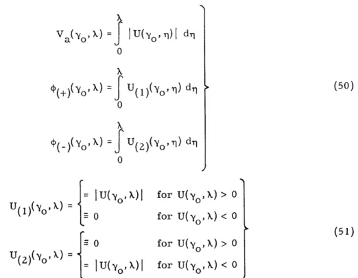
(y', X), T(y o , X), T(yo , X) justify the writing of integrals (43) to (46) as the difference of integrals, where (+), (_), T(+), T(_), T +), T (_)are always real, non-negative,
nondecreasing, etc., functions.
Hence
f(t)
=
f(
1)(t)
-
f(
2)(t) =
os
ro2(s - y )
F(s) = F(1)(s)- F(2)(s) = IXt
d()(y, ) -e cos Xt d(_)( 0X),To
d (+ )(Y0 ,X) 2(s- -y ) (s - yo) 2z T+ro
(52)I
dP( )(Y (53)(s -
o
)+ X(53)
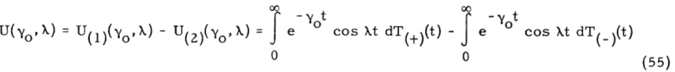
1o
U(, X)= U(
1)(Yo,X)
- U(
2)(Y0
,
X)=
f
cosXt
dT )(, t) -Scos
t
dTr)(y0 ,t)0 0