HAL Id: cea-02194487
https://hal-cea.archives-ouvertes.fr/cea-02194487
Submitted on 25 Jul 2019
HAL is a multi-disciplinary open access
archive for the deposit and dissemination of
sci-entific research documents, whether they are
pub-lished or not. The documents may come from
teaching and research institutions in France or
abroad, or from public or private research centers.
L’archive ouverte pluridisciplinaire HAL, est
destinée au dépôt et à la diffusion de documents
scientifiques de niveau recherche, publiés ou non,
émanant des établissements d’enseignement et de
recherche français ou étrangers, des laboratoires
publics ou privés.
Simultaneous mode tracking for sensing applications
with dual-mode heterodyne NEMS oscillator
Sebastien Hentz, Guillaume Gourlat, Marc Sansa, Guillaume Jourdan, Patrick
Villard, Gilles Sicard
To cite this version:
Sebastien Hentz, Guillaume Gourlat, Marc Sansa, Guillaume Jourdan, Patrick Villard, et al..
Simulta-neous mode tracking for sensing applications with dual-mode heterodyne NEMS oscillator. 2016 IEEE
SENSORS, Oct 2016, Orlando, United States. 3 p., �10.1109/ICSENS.2016.7808662�. �cea-02194487�
Simultaneous mode tracking for sensing applications
with dual-mode heterodyne NEMS oscillator
Guillaume Gourlat, Marc Sansa, Guillaume Jourdan, Patrick Villard, Gilles Sicard, Sébastien Hentz.
Univ. Grenoble Alpes, F-38000 Grenoble, FranceCEA, LETI, MINATEC Campus, F-38054 Grenoble, France guillaume.gourlat@cea.fr
Abstract— We report the first experimental demonstration of
a heterodyne self-oscillator operating simultaneously on the first and second mode of a silicon NEMS resonator. This architecture tackles the simultaneous monitoring of a doubly-clamped resonator’s first two resonant modes required for real world applications in the field of biological mass sensing. This oscillator is based on a downmixing scheme where the NEMS motion-induced electrical signal around 25 MHz and 70 MHz is shifted down to few tens of kilohertz thus reducing the bandwidth constraint on electronics and limiting the feedthrough between the NEMS actuation and detection electrode. In this paper, we present the oscillator measurement results in open-loop and closed-loop, and we evaluate the frequency stability. When implemented on silicon this oscillator scheme will help to circumvent today’s limited NEMS integration density mostly due to a bulky circuitry.
Keywords—NEMS, MEMS, oscillator, resonator, mass spectrometry, mass sensing, heterodyne, dual-mode
I. INTRODUCTION
NEMS (Nano Electro Mechanical System) extreme sensitivity to small physical variations makes them excellent candidates for gas [1] or mass sensing applications [2]. Such applications require densely packed arrays of resonators to circumvent the small capture area of individual sensors. Parallel sensing requires a process with a high interconnection density and a compact readout circuitry capable of tracking the frequency response of each resonator in the array individually. The 3D sequential co-integration of silicon NEMS above industrial CMOS wafers with the so-called CEA/LETI “CoolCubeTM” promises good integration density[3]. While
NEMS-CMOS co-integration is of paramount importance, the readout circuitry’s footprint remains the limiting factor to a dense integration of thousands of devices.
Moreover, mass sensing applications increase the system complexity as they need to track simultaneously two resonance modes (Fig. 1b) for each device in order to resolve both the added mass and its position [2] [4]. The most common closed loop readout architectures of single devices [5] is a phase locked loop (PLL). This readout scheme, requiring a bulky readout circuit consists in maintaining the phase shift introduced by the NEMS at its resonant value by controlling its actuation frequency through a controlled oscillator. Self-oscillating loops (SOL) [6] can also be used, they are much more compact and therefore compatible with array’s readout density constraints. But this architecture still suffers from very high sensitivity to parasitic signals making it difficult to sustain and track multiple oscillation modes. We propose here an improved version of the
heterodyne self-oscillator approach [7] capable of simultaneously tracking two modes of resonance of a NEMS without degrading the resonator mass resolution and sensitivity. Section II describes the resonator’s design and the dual mode heterodyne oscillator setup. Finally, the experimental results for open loop and closed loop operations are given and the frequency stabilities are compared.
II. EXPERIMENTAL SETUP
A. NEMS resonator description
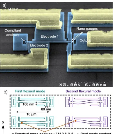
The nanomechanical resonator used here is a monocrystalline silicon doubly-clamped beam with compliant anchors for enhanced dynamic range as shown in Fig. 1a and in [2]. The resonators are fabricated on the silicon layer of a
Fig. 1. Colorized scanning electron microscope image a) of a suspended in-plane doubly-clamped silicon NEMS resonators used for measurement. The beam is 10μm long, 160 nm thick and 300nm wide. The nanogauges are 80 nm wide. Light blue corresponds to the silicon and light yellow to the metallic connections. The electrode gap is 100nm wide. Diagram b) of the first two flexural modes.
silicon-on-insulator wafer. The NEMS topology features a beam that is 160nm thick, 300nm wide and 10μm long. The resonator is electrostatically actuated by one of the two actuation electrodes which are designed to improve the first and second mode actuation efficiencies respectively. The resulting in-plane motion is transduced in the electrical domain thanks to two piezoresistive nanoscale gauges (80 nm) in bridge configuration for background cancellation. Their good electrical conductivity is obtained by high boron doping level [8]. The device operates under vacuum (typically 10-5mbar) at room temperature. The
device embeds a detection scheme where the gauges are biased with a harmonic signal at a frequency close to the nominal resonant frequency of the NEMS. Therefore, the motion induced strain in the gauges is downmixed to a lower frequency in the range of hundreds of kilo hertz enabling the off chip measuring and relaxing the sustaining electronics bandwidth requirement by more than one decade.
B. Oscillator system description
In the self-oscillating loop readout, the sustaining electronics around the NEMS ensures that the Barkhausen conditions are met in each oscillator loop. Each loop consists in a low noise amplifier with a built-in tunable first order bandpass filter featuring lower and upper cutoff frequencies respectively set at
30Hz and 1MHz. Then, we use a combination of low pass and high pass highly selective filters that respectively filter out the second mode in the blue path and the first mode in the purple path of Fig. 2 a). Finally, the filtered signals are up-mixed, phase shifted by a mixer, DC biased and fed back to the resonator’s respective actuation electrode. The phase between the gauges bias signal and the up-mixing bias signal is controlled to fulfill the loop phase conditions. Compared to homodyne oscillators, the heterodyne one introduces a phase shifter and requires an external RF biasing signal. However this signal does not need to be at the exact resonant frequency of the NEMS, and therefore can be shared between all the resonators in the array readout context. Fig. 2 describes the dual mode oscillator and follows describes the electrical oscillation along the loops with our signal data.
III. MEASUREMENT RESULTS
A. Open loop operations
The resonator used in this work is measured in open loop using the conventional downmixing scheme [9]. Since the NEMS actuation conditions may vary slightly when closing the loop due to impedance variations, we characterize the resonator for multiple AC and DC actuation conditions in order to get good understanding of the NEMS behavior over a wide range of operating points. The AC and DC signals are respectively swept from 50mV to 450mV by steps of 50mV on electrode 1 and 2 for both modes. Fig.3 presents the amplitude of the frequency response of the resonator (phase data has been recorded but is not shown here). The NEMS exhibits a resonant frequency and a quality factor of 25.98MHz and 6000 for the first mode, and of 71.91MHz and 4200 for the second mode. We expect to see a nonlinear behavior due to the NEMS for actuation voltages greater than 200mV DC and 200mV AC for mode 1, and 450mV DC and 450mV AC for mode 2.
B. Closed loop operations
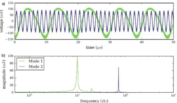
Fig. 4 shows the outputs of the dual-mode heterodyne oscillator working simultaneously on the first two resonant modes of a single NEMS resonator. The oscillator exhibits respectively a 103 kHz and 758 kHz downmixed oscillation frequencies for mode 1 and 2. The signal presents good signal-to-noise ratio, and a slight non linearity for the first mode. The
Fig. 3. Measurement of the open loop response of the NEMS resonator for the first mode a) and second mode b). Frequency response has been measured for multiple DC (from 50 mV to 450 mV) and AC (from 50 mV to 250 mV) actuation voltage level in order to have an operating point map for closed loop operation behavior analysis.
Fig. 2 Schematic a) of the dual-mode heterodyne oscillator tracking simultaneously the first two modes of the resonator. Blue and purple correspond to the first mode and second mode paths respectively. Photography of the setup b) and vacuum chamber c).
resonator’s frequency stability (Fig.5) in open loop was measured and compared with the closed loop frequency stability of the feedback signal in order to evaluate the performance of the topology for mass sensing applications. For this purpose, we use the standard estimator of the frequency stability versus measurement time known as Allan deviation [10]. In open loop, the frequency is deduced from phase fluctuations at the output and the linearized phase-to-frequency response of the resonator close to resonance. In closed loop operation, the frequency is acquired in real-time by locking a PLL on the low frequency downmixed signal. The closed and open loop frequency stability of the first and second mode shows a slight degradation at low response time. This noise increase is partially attributed to the complex cabling and parasitic due to the presence of discrete components in the loop. Silicon integration of the sustaining electronics should alleviate the noise coming from the readout circuitry while maintaining the resonator performance.
IV. CONCLUSION
This work demonstrates for the first time the simultaneous operation of a heterodyne self-oscillator topology on the first two resonant modes of a NEMS device. This multiple mode tracking capability is necessary for applications such as mass sensing. When integrated on silicon, this topology will be much more compact than traditional multimode PLL and less sensitive to parasitic oscillations compared to homodyne oscillators. The readout scheme aims at increasing the NEMS density of integration that is still limited by bulky circuitry. In this work we have characterized our resonator in open loop and successfully sustained simultaneous oscillations of two resonant modes in closed loop operation. For integration time superior to 100ms, the closed-loop frequency stability shows no sign of degradation compared to the open loop results. The proposed topology and simultaneous multiple mode tracking does not introduce substantial noise. This oscillator architecture promises reduced silicon footprint compatible with the readout of dense sensor arrays required for mass sensing applications.
ACKNOWLEDGMENT
The authors thank the Carnot institute (Project NEMS MS) and “Direction générale de l’armement” for financial support
REFERENCES
[1] J. Arcamone, A. Niel, V. Gouttenoire, M. Petitjean, N. David, R. Barattin, M. Matheron, et al, « VLSI silicon multi-gas analyzer coupling gas chromatography and NEMS detectors », in Electron Devices Meeting
(IEDM), 2011 IEEE International, 2011, p. 29.3.1̻29.3.4.
[2] E. Sage, A. Brenac, T. Alava, R. Morel, C. Dupré, M. S. Hanay, M. L. Roukes, L. Duraffourg, C. Masselon, et S. Hentz, « Neutral particle mass spectrometry with nanomechanical systems », Nat. Commun., vol. 6, mars 2015.
[3] W. Ludurczak, G. Gourlat, M. Gely, G. Billiot, J. Philippe, P. Villard, G. Sicard, T. Ernst, et S. Hentz, « Large scale integration of silicon nanomechanical resonators above industrial cmos wafers », unpublished. [4] M. S. Hanay, S. Kelber, A. K. Naik, D. Chi, S. Hentz, E. C. Bullard, E. Colinet, L. Duraffourg, et M. L. Roukes, « Single-protein nanomechanical mass spectrometry in real time », Nat. Nanotechnol., vol. 7, no 9, p. 602̻608, sept. 2012.
[5] J. Arcamone, C. Dupré, G. Arndt, E. Colinet, S. Hentz, E. Ollier, et L. Duraffourg, « VHF NEMS-CMOS piezoresistive resonators for advanced sensing applications », Nanotechnology, vol. 25, no 43, p. 435501, oct.
2014.
[6] J. Philippe, G. Arndt, E. Colinet, M. Savoye, T. Ernst, E. Ollier, et J. Arcamone, « Fully monolithic and ultra-compact NEMS-CMOS self-oscillator based-on single-crystal silicon resonators and low-cost CMOS circuitry », in 2014 IEEE 27th International Conference on Micro Electro
Mechanical Systems (MEMS), 2014, p. 1071̻1074.
[7] G. Gourlat, M. Sansa, G. Jourdan, P. Villard, G. Sicard, et S. Hentz, « Dual-mode NEMS self-oscillator for mass sensing », in Frequency
Control Symposium the European Frequency and Time Forum (FCS), 2015 Joint Conference of the IEEE International, 2015, p. 222̻225.
[8] E. Mile, G. Jourdan, I. Bargatin, S. Labarthe, C. Marcoux, P. Andreucci, S. Hentz, C. Kharrat, E. Colinet, et L. Duraffourg, « In-plane nanoelectromechanical resonators based on silicon nanowire piezoresistive detection », Nanotechnology, vol. 21, no 16, p. 165504, avr.
2010.
[9] I. Bargatin, E. B. Myers, J. Arlett, B. Gudlewski, et M. L. Roukes, « Sensitive detection of nanomechanical motion using piezoresistive signal downmixing », Appl. Phys. Lett., vol. 86, no 13, p. 133109, mars
2005.
[10] IEEE Standard Definitions of Physical Quantities for Fundamental
Frequency and Time Metrology - Random Instabilities. IEEE, 1999.
Fig. 4. Measurement of the closed loop operation working simultaneously on the first and second resonant mode of the NEMS. The time results a) and FFT results b).
Fig. 5. Comparison of the frequency stability of the oscillator in closed loop (red line) with the intrinsic frequency stability of the resonator (blue line) for the first a) and second b) mode of operation. (power line’s harmonic at 50Hz removed and 4Hz parasitic removed)