HAL Id: hal-00873701
https://hal.archives-ouvertes.fr/hal-00873701
Submitted on 16 Oct 2013
HAL is a multi-disciplinary open access
archive for the deposit and dissemination of
sci-entific research documents, whether they are
pub-lished or not. The documents may come from
teaching and research institutions in France or
abroad, or from public or private research centers.
L’archive ouverte pluridisciplinaire HAL, est
destinée au dépôt et à la diffusion de documents
scientifiques de niveau recherche, publiés ou non,
émanant des établissements d’enseignement et de
recherche français ou étrangers, des laboratoires
publics ou privés.
Real-Time Online Monitoring of the Ion Range by
Means of Prompt Secondary Radiations
J. Krimmer, L. Balleyguier, J. Baudot, S. Brons, L. Caponetto, M. Chabot,
X. Chen, M. Dahoumane, D. Dauvergne, M. de Rydt, et al.
To cite this version:
J. Krimmer, L. Balleyguier, J. Baudot, S. Brons, L. Caponetto, et al.. Real-Time Online Monitoring
of the Ion Range by Means of Prompt Secondary Radiations. 3rd International Conference On
Ad-vancements In Nuclear Instrumentation Measurement Methods And Their Applications (ANIMMA
2013), Jun 2013, Marseille, France. pp.1-8, �10.1109/ANIMMA.2013.6728046�. �hal-00873701�
Real-Time Online Monitoring of the Ion Range by
Means of Prompt Secondary Radiations
J. Krimmer
∗, L. Balleyguier
∗, J. Baudot
†, S. Brons
‡,L. Caponetto
∗, M. Chabot
§, X. Chen
∗, M. Dahoumane
∗,
D. Dauvergne
∗, M. De Rydt
∗, G. Dedes
∗, R. Della Negra
∗, S. M. Deng
∗, P. Force
‡‡, N. Freud
k, B Joly
‡‡,
J. H´erault
∗∗, C Insa
‡‡, D. Lambert
‡‡, C. La Tessa
††, L. Lestand
‡‡, J.M. L´etang
k, J.-L. Ley
∗, X. Lojacono
k,
M. Magne
‡‡, H. Mathez
∗, V. Maxim
k, G. Montarou
‡‡, K. Parodi
x,11, M. Pinto
∗, R. Pleskac
††, D. Prieels
xii,
R. Prost
k, C. Ray
∗, M.H. Richard
∗, V. Reithinger
∗, I. Rinaldi
x, F. Roellinghoff
∗, J. Smeets
xii, E. Testa
∗,
M. Vanstalle
††, M. Winter
†and Y. Zoccarato
∗∗Institut de Physique Nucl´eaire de Lyon; Universit´e de Lyon, F-69003 Villeurbanne, France; IN2P3/CNRS, UMR 5822;
Universit´e de Lyon 1, F-69622 Villeurbanne, France
†Universit´e de Strasbourg, CNRS/IN2P3, Institut Pluridisciplinaire Hubert Curien,
23 rue du Loess 67037 Strasbourg, France
‡Heidelberg Ion Beam Therapy center (HIT), Im Neuenheimer Feld 400, D-69120 Heidelberg, Germany §IPNO, Universit´e Paris Sud, 91406 Orsay, France
¶Instituut voor Kern- en Stralingsfysica, KU Leuven, Celestijnenlaan 200D, B-3001 Leuven,Belgium kUniversit´e de Lyon, CREATIS; CNRS UMR5220; Inserm U1044; INSA-Lyon; Universit´e Lyon 1; CLB, France
∗∗Centre Antoine Lacassagne, Cyclotron Biom´edical, 227 avenue de la Lanterne, 06200 Nice, France ††GSI Helmholtzzentrum f¨ur Schwerionenforschung GmbH, Planckstraße 1, 64291 Darmstadt, Germany
‡‡Clermont Universit´e, Universit´e Blaise Pascal, CNRS/IN2P3, Laboratoire de Physique Corpusculaire,
BP 10448, F-63000 Clermont-Ferrand, France
x
Dep. Radiation Therapy and Radiation Oncology University Clinic Heidelberg, Im Neuenheimer Feld 400 D-69120 Heidelberg, Germany
xi
Ludwig Maximilians University (LMU) Munich, Am Coulombwall 1 D-85748 Garching, Germany
xii
IBA, Louvain la Neuve, Belgium
Abstract—Prompt secondary radiations such as gamma rays and protons can be used for ion-range monitoring during ion therapy either on an energy-slice basis or on a pencil-beam basis. We present a review of the ongoing activities in terms of detector developments, imaging, experimental and theoretical physics issues concerning the correlation between the physical dose and hadronic processes.
I. INTRODUCTION
The treatment of tumors by a beam of carbon ions or protons is an emerging method for cancer therapy. One of the advantages of this method is the fact that the ions deposit a large quantity of their dose at the end of their path in the Bragg peak which allows a maximization of the dose applied to the tumor and a minimization of the dose hitting healthy tissue. The lateral dose distribution is also quite narrow, it is mainly effected by multiple scattering of the charged projectiles before stopping. Another advantage, compared to conventional radiotherapy, is the higher relative biological effectiveness. Due to the sharp falloff, one of the major issues for quality control during the treatment with ion beams is the control of the Bragg peak position and its conformation to the tumor volume. A mispositioning would either lead to an over-dosage of healthy tissue and/or an under-dosage in the target volume. Since no primary radiation is emerging from the patient during treatment, secondary radiation is used for in vivo monitoring
purposes. The secondary radiation needs to have a weak interaction probability to reach external detectors and it needs to be correlated to the primary beam dose distribution. This information on electromagnetic energy distribution (the LET) can be extracted from hadronic interactions [1]–[3].
Several techniques have been deployed for this purpose. The detection of the two 511 keV gammas following a β+
decay [4] via a PET scanner has already proven its applicability in hadrontherapy (see e.g [5], [6]). This method suffers however from long acquisition times due to the limited number of β+
emitters produced in fragmentation processes of the incident ions. Therefore, biological wash-out needs to be taken into account when deducing the absorbed dose from the measured activity.
Other modalities involve prompt secondary radiation, either via detection of prompt gamma rays [7], [8], or light charged particles [9]. The present article focuses on these modalities with a special emphasis on the instrumental developments and simulations. The paper is organized as follows: Section II introduces two modalities for prompt gamma imaging, which is followed in Section III by a description of proton vertex imaging. The beam tagging hodoscope is subject of Sec-tion IV. Finally, SecSec-tion V, deals with our simulaSec-tion activities.
II. PROMPT-GAMMA IMAGING
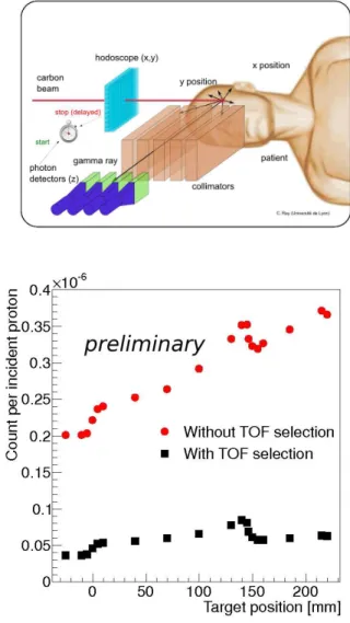
During an irradiation, photons in the range 1-10 MeV are emitted almost isotropically within much less than a picosecond after the nuclear reactions. It has been shown that the production rate of these prompt gammas is highly correlated to the dose deposited by the incident ions [7], [8]. The position of the Bragg peak can be determined via a detection of the fall off in the production rate of the prompt gammas. In Lyon two systems for prompt gamma detection are developed, a collimated camera and a Compton camera, which will described in the following subsections.
A. Collimated camera
Several groups worldwide are developing prompt gamma-ray detection systems based on passive collimation with the objective of an online monitoring of the ion range during hadrontherapy (see e.g. [7], [10]–[12]). The principle of the present system is shown in Fig. 1 (top). The incident ions are passing a beam tagging hodoscope (see Section IV) which determines the position and provides a time stamp. In order to obtain a position information of the produced prompt gammas, they are traversing a collimator consisting of parallel plates. The detectors behind the slits register the photons and provide a timing information, also. This timing information can be used to select the prompt gammas in a time-of-flight (TOF) spectrum in order to discriminate against neutrons which are not correlated to the ion range [13] and therefore only contribute to the background.
The concept has been successfully tested at carbon ion and proton beamlines with a large variety of incident ion energies. The time reference for the TOF selection can either be obtained from a thin scintillator in the primary (continuous) beam or from the HF structure of pulsed beamlines (e.g. at GANIL). In Fig. 1 (bottom) a prompt gamma profile obtained at a 160 MeV proton beam at the WPE (Westdeutsches Protontherapiezentrum Essen) is given. For this experiment a collimator with a single slit has been used, the profile has been obtained by scanning the target (a PMMA cylinder with a diameter of 150 mm and a length of 250 mm) in front of the collimator. For photon-detection we used LYSO and LaBr3 scintillation detectors, respectively, which have a ns
timing resolution. The obtained background is less than for comparable experiments at carbon ion beams. But also for the proton beam the TOF selection yields to a significant background reduction.
The purpose of the here described methods is to detect the fall-off in the prompt gamma production rate after the Bragg peak in order to have a measure of the incident ion range. For a determination of this range retrieval precision as a function of the available statistics, the full data set has been split to sub-samples with variable statistics. It turned out that for a detection of the Bragg peak position with a precision of 3 mm about 109
incident protons are necessary [14].
Typical ion numbers for a distal energy slice during treat-ment are given in Table I [12], [15], [16]. Combining these numbers with the above mentioned results, 10 detectors behind
Fig. 1. Principle of prompt gamma detection (top) and a prompt gamma profile at a 160 MeV proton beam, with and without time of flight selection (bottom).
TABLE I
TYPICAL NUMBER OF IONS DURING TREATMENT[12], [15], [16] number of ions (distal slice) proton carbon energy slice ∼ 1010 ∼ 108 single spot ∼ 108 ∼ 106
a single slit are necessary to have a 3 mm precision for a single spot at proton treatment. For carbon therapy less ions are necessary to provide the therapeutic dose in the target volume. In this case the signal from several or all spots from an energy slice (supposed the penetration depth is the same) need to be integrated for a sufficiently high statistics.
First measurements have been performed in order to mea-sure longitudinal prompt gamma ray profiles with a multislit collimator configuration. The experimental setup with LYSO
100mm 2mm 6.2mm W−collimator PMMA target 600mm C 75MeV/u 13 600mm Pb−collimator 100mm 2mm 200mm LYSO 1−4 LYSO 5
Fig. 2. Setup of a multislit configuration (top) and corresponding longitudinal prompt gamma ray profiles obtained at a13
C beam with 75 MeV/u (bottom).
scintillation detectors behind lead or tungsten collimators, respectively, is given in Fig. 2 (top). The experiment has been performed at GANIL with 75 MeV/u 13C ions. The profile (Fig. 2 (bottom)) has been obtained via a scan of the PMMA target in front of the detectors. For clarity, the constant offset of the detector positions has been taken out for the plot. The difference in the yield for the different detectors is due to the nonuniform efficiencies of the detectors. Nevertheless, all counters reveal the fall-off in the prompt gamma production rate at the same position. There is some structure in the profiles which seems to come from regions outside the target (see e.g. the bump around 5 mm for LYSO 2). These events can be attributed to Compton scattering from one detector to another. Although this Compton scattering contribution is not negligible, it should not be crucial for a realistic collimated camera. Currently the collimator design is being optimized via Monte Carlo simulations aiming for the construction of a prototype.
Besides the measurement with homogeneous targets presented so far, longitudinal prompt gamma-ray profiles have also been obtained with heterogeneous targets where inserts with low and high density material represented lung and bone tis-sue, respectively. A correlation between the produced prompt gamma rate and the density variations could be observed [17]. Furthermore, the retrieved ion range is in accordance with simulations.
B. Compton camera
A considerable improvement in the detection of prompt photons can be achieved with a Compton camera. The idea is to replace the performance limiting passive collimation via electronic collimation. For medical applications several systems with different detector configurations are under development (see e.g. [18]–[24]). The principle of the envisaged design of the Compton camera is displayed in Fig. 3. An emitted gamma ray undergoes Compton scattering in a first (scatter) detector and hits then the absorber. With the position and energy information of these detectors as well as the Compton kinematics the direction of the original photon can be confined to a cone. The originality of the present system is the use of the beam tagging hodoscope which simplifies the reconstruction problem to an intersection of a straight line with a cone, whereas classical Compton cameras obtain the 3-D information of the produced gammas from cone intersections.
Simulations have been performed [25], [26] with a stack
Fig. 3. Scheme of the combination of a Compton camera and a beam tagging hodoscope.
of 10 silicon strip detectors (2 mm thickness) as scatter detectors and a large scintillator as absorber. According to the simulations this setup provides an efficiency of 2.5·10−4
and has a spatial resolution for a polychromatic point-source of 8.3 mm FWHM [26]. For a measurement of the ion range during hadrontherapy, i.e. a detection of the fall-off position in the gamma profile, millimetric precision can be reached [27], however. The spatial resolution can be further improved by the application of advanced reconstruction algorithms [28]–[31].
For a realistic determination of the occurring count rates during hadrontherapy an experiment at the Heidelberg Ion Therapy center (HIT) has been performed with a Compton-camera-like setup (see Fig. 4 (top)). A small silicon strip detector (12×12 × 2 mm3
) has been combined with a LaBr3
scintillator (diameter 25.4 mm, length 50.8 mm). The mea-sured energy spectrum for the silicon detector in comparison with simulations from [27] are shown in Fig. 4 (bottom).
beam
scint. beam
target
LaBr det.
3silicon det.
scint. CC
I.C.Fig. 4. Top: Experimental setup at HIT with a Compton-camera-like con-figuration for count rate measurements. Bottom: Measured energy spectra in comparison with simulations for the silicon detector.
With these data we extrapolated the expected count rates for a configuration as in [26], i.e. silicon detectors with 80×80 × 2 mm3
and an absorber with 300×300 × 25 mm3
. The expected count rates under typical therapeutic beam conditions with proton or carbon beams, respectively, are given in Table II.
TABLE II
COUNT RATE ESTIMATES FOR A REAL SIZECOMPTON CAMERA UNDER THERAPEUTIC BEAM CONDITIONS
proton beam (1010 p/s) carbon beam (108 ion/s) count/s count/s first Si 4.4·106 1.3·106 absorber 2.5·107 2.8·106
It can be seen that the rate for the first silicon detector in the stack is on the order of 106 1/s for the whole detector which reduces to 105
1/s for a single strip. This is a rate which can be handled by the electronics. For the absorber however, the expected rates reach 107
1/s, which is not feasible. The envisaged solution is the usage of a segmented absorber detector consisting of BGO crystals coming from PET mod-ules [32]. The blocks are sawn-in (see Fig. 5 (left)) for an improvement of the position resolution. They are read out via 4 photomultiplier tubes (Fig. 5 (right)). Simulations [33] have shown that BGO is well suited for the considered purpose as
the high photo-electric cross section leads to a large quantity of fully absorbed photons in the crystal. Furthermore, it has a sufficiently good timing resolution and compared to LYSO, BGO has the advantage of not being radioactive.
Fig. 5. sawn-in BGO crystal (left) read out via 4 photomultiplier tubes (right).
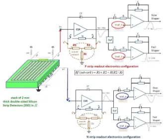
As scatter detectors double sided silicon strip detectors (DSSD) [34] with 2×64 strips and a volume of 90×90×2mm3
will be used (Fig. 6). They have been bonded and mounted on a test board for characterization.
Fig. 6. Large silicon detector with 2× 64 strips mounted on a test board.
Fig. 7. Scheme of readout electronics [35] for the SSD.
For the readout a dedicated application specific integrated circuit (ASIC), as shown in Fig. 7, has been developed [35]. It consists of charge sensitive preamplifiers (CSA) as well as fast and slow shapers with 15 ns and 1 µs shaping times,
respectively. The aim for the DSSD and its readout is to obtain an energy resolution of 2 keV FWHM at 1 MeV. In the present version of the ASIC 75% of the noise is produced by the resistance in the feedback loop of the slow shaper. In the next version of the layout this resistance will be replaced by a switch in order to completely suppress its contribution to the parallel noise.
III. PROTONINTERACTIONVERTEXIMAGING
Another method, complementary to the detection of prompt gamma rays, is the analysis of the emission of charged particles following the fragmentation of the incident ions. The principle is to reconstruct the trajectories of the emitted particles and to extrapolate them to the point of creation (vertex) [9]. Fig. 8 shows the principle. The direction of the incident ion is defined by the beam tagging hodoscope. The trajectory of the secondary protons is registered via planes of pixel detectors (MIMOSA26 [36]). A scintillator, operated in coincidence with the beam tagging hodoscope, serves as trigger.
Simulations [37] have shown that the emitted protons carry
Fig. 8. Principle of Proton Interaction Vertex Imaging
information about the range of the incident ions, more sur-prisingly even in the case of deep seated tumors where the residual range of the protons to escape the patient reaches 10 cm (for homogeneous targets). Results from the simulations for a spherical head phantom (diameter 200 mm) are given in Fig. 9. Here, the distribution of vertex yields is shown for different incident carbon ion energies. For a quantitative analysis an error-function has been fitted to the distributions, the inflection point position (IPP) is indicated in the figure, also. A correlation of the IPP and the incident carbon ion energy is revealed.
In order to validate the proton IVI method, several experi-ments have already been performed. The configuration with a 100 ×100×250mm3
PMMA target at the carbon beam of HIT is shown in Fig. 10 (top). The yield of reconstructed vertices, as measured, is given in the bottom part of Fig. 10. For comparison, also the stopping power of carbon ions in PMMA at this energy is shown. Data have been taken at various incident ion energies showing an influence in the reconstructed
Fig. 9. Results from simulations [37] of a spherical head-phantom for the vertex yield at different carbon ion energies. IPP denotes the inflection point position of a fitted error-function.
vertex distributions [38] (cf Fig. 9). Moreover, measurements
Fig. 10. Experimental configuration at HIT (top) and measured reconstructed vertices in comparison to the corresponding stopping power (bottom).
with heterogeneous targets have been performed recently at HIT. Data analysis is in progress.
IV. BEAM TAGGING HODOSCOPE
The beam tagging hodoscope plays a major role in all our detection concepts as it provides position and timing information of the incident ions. It consists of an array of scin-tillating fibers (1 × 1mm2
) which are coupled to multichannel photomultipliers (PM). Two prototypes already exist, one with
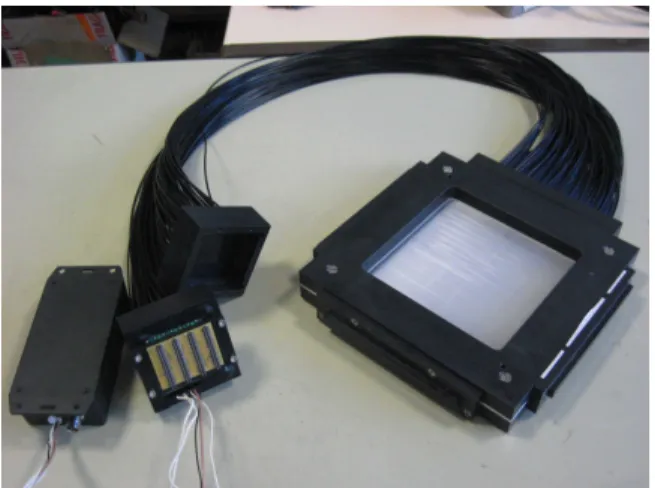
2×32 fibers and another with 2×128 fibers (see Fig. 11). Both prototypes have been successfully tested. From measurements at GANIL with the small hodoscope, a time resolution of 1 ns FWHM could be extracted.
For the choice of the PM, a micro-channel-plate PM
(MCP-Fig. 11. The beam tagging hodoscope with 2× 128 scintillating fibers
PMT) and a multi-anode PM (MA-PM, H-8500) have been investigated for their maximum count rate capabilities. The measurements have been performed with 25 MeV protons of the Orsay tandem accelerator. Results of these tests are displayed in Fig. 12. As the MCP-PMT has less gain than the MA-PMT, it had to be operated close to its maximum voltage to provide sufficiently large signals. This led to a maximum count rate of several 105 1/s, whereas with the H-8500 more than 107 1/s could be achieved, when operated at 800 V. For a further improvement of the maximum count rate of the
Fig. 12. Maximum count rates for two photomultiplier types at different high voltages
hodoscope, adjacent scintillating fibers are coupled to different PMs (8 PMs are used in total). One fiber is read out from both ends which leads to an increase in efficiency. Furthermore, by calculating the arithmetic mean, a timing information independent on the impact position can be obtained.
x fibers 0 2 4 6 8 10 12 14 16 y fibers 0 2 4 6 8 10 12 14 16 1000 2000 3000 4000 5000 6000 7000 8000
Fig. 13. Beam profile, measured with 25 MeV protons.
A beam profile, measured with the 25 MeV protons, is shown in Fig. 13. During this test, some channels didn’t work (like x5) or gave a noisy signal (like x15).
A. Front end electronics
For the front end electronics of the hodoscope, two ASICs integrating different functionalities have been fabricated and tested [39]. Each channel contains a current comparator and a charge sensitive amplifier [40] and provides a digital output when its analog input signal crosses a programmable threshold. The analog output signal produced by the charge amplifier can be used to measure the produced charge. The second ASIC provides a timing information with a resolution of 140 ps [39]: it uses a 160 MHz external clock in combination with an internal 32 bit Delay Locked Loop (DLL) encoded into a 5 bit time-stamp and is capable of an acquisition rate of 100 MHz. A new ASIC integrating both functionalities and 32 channels will be available by the beginning of September 2013.
V. GEANT4SIMULATIONS
Simulations with the Geant4 toolkit [41] are performed to reproduce dose and emitted secondary radiation caused by incident protons and carbon ions. They are used also for feasibility studies and for the optimization of detection setups. In the case of prompt-gamma production the results from Geant4 showed a massive overestimation of the produced rate compared to experimental data [42]. This led to the necessity for an improvement of the hadronic models within Geant4. A recent work focused on the refinement of the Quantum Molecular Dynamic (QMD) model [43], [44], which describes the dynamic part of ion-ion collisions. The QMD model contains parameters like the width L of the nucleon wave packet, which are free within a certain range. L has been optimized in a way to reduce the number of produced prompt gammas but to leave other fundamental physical properties like the nuclear binding energy unchanged. A thorough description of the improvements for the Geant4 hadronic models in the context of prompt gamma monitoring will be given in [45].
VI. CONCLUSION
Developments for the detection of prompt secondary radia-tion have been presented. It has been shown that for hadron-therapy with active beam delivery a millimetric monitoring of the ion range is feasible on a single-spot basis for proton beams or on an energy slice basis for carbon ions. Measurements with homogeneous and heterogeneous targets have been performed. The later are a first step towards morphologic phantoms or in vivo measurements. Monte Carlo simulations play an important role in the design and optimization of prototypes.
ACKNOWLEDGMENT
This work is supported by the FP7-ENVISION program (WP3 and WP6), the ENTERVISION program, the FP7-ULICE program, the INSERM-’Physique Cancer’ QAPIVI project, the ANR Gamhadron project, the Rhˆone-Alpes Re-gional Program for Hadrontherapy Research, the MI2B GDR, and the LabEx PRIMES.
REFERENCES
[1] D. Schardt, I. Schall, H. Geissel, H. Irnich, G. Kraft, A. Magel, M. Mohar, G. Munzenberg, F. Nickel, C. Scheidenberger, W. Schwab, and L. Sihver, “Nuclear fragmentation of high-energy heavy-ion beams in water,” Adv. Space Res., vol. 17, no. 2, pp. 87–94, 1996.
[2] T. Inaniwa, T. Kohno, T. Tomitani, E. Urakabe, S. Sato, M. Kanazawa, and T. Kanai, “Experimental determination of particle range and dose distribution in thick targets through fragmentation reactions of stable heavy ions,” Physics in Medicine and Biology, vol. 51, no. 17, p. 4129, 2006. [Online]. Available: http://stacks.iop.org/0031-9155/51/i=17/a=002
[3] N. Matsufuji, A. Fukumura, M. Komori, T. Kanai, and T. Kohno, “Influence of fragment reaction of relativistic heavy charged particles on heavy-ion radiotherapy,” Physics in Medicine and Biology, vol. 48, no. 11, p. 1605, 2003. [Online]. Available: http://stacks.iop.org/0031-9155/48/i=11/a=309
[4] G. Shakirin, H. Braess, F. Fiedler, D. Kunath, K. Laube, K. Parodi, M. Priegnitz, and W. Enghardt, “Implementation and workflow for pet monitoring of therapeutic ion irradiation: a comparison of in-beam, in-room, and off-line techniques,” Physics in Medicine
and Biology, vol. 56, no. 5, p. 1281, 2011. [Online]. Available:
http://stacks.iop.org/0031-9155/56/i=5/a=004
[5] W. Enghardt, P. Crespo, F. Fiedler, R. Hinz, K. Parodi, J. Pawelke, and F. Pnisch, “Charged hadron tumour therapy monitoring by means of{PET},” Nuclear Instruments and Methods
in Physics Research Section A: Accelerators, Spectrometers, Detectors
and Associated Equipment, vol. 525, no. 1-2, pp. 284 –
288, 2004, ¡ce:title¿Proceedings of the International Conference on Imaging Techniques in Subatomic Physics, Astrophysics, Medicine, Biology and Industry¡/ce:title¿. [Online]. Available: http://www.sciencedirect.com/science/article/pii/S0168900204004218 [6] T. Nishio, T. Ogino, K. Nomura, and H. Uchida, “Dose-volume delivery
guided proton therapy using beam on-line pet system,” Medical Physics, vol. 33, p. 4190, 2006.
[7] C.-H. Min, C. H. Kim, M.-Y. Youn, and J.-W. Kim, “Prompt gamma measurements for locating the dose falloff region in the proton therapy,”
Applied Physics Letters, vol. 89, no. 18, p. 183517, 2006. [Online].
Available: http://link.aip.org/link/?APL/89/183517/1
[8] E. Testa, M. Bajard, M. Chevallier, D. Dauvergne, F. L. Foulher, N. Freud, J.-M. Letang, J.-C. Poizat, C. Ray, and M. Testa, “Monitoring the bragg peak location of 73 mev/u carbon ions by means of prompt gamma-ray measurements,” Applied Physics
Letters, vol. 93, no. 9, p. 093506, 2008. [Online]. Available:
http://link.aip.org/link/?APL/93/093506/1
[9] U. Amaldi, W. Hajdas, S. Iliescu, N. Malakhov, F. Samarati, J.and Sauli, and D. Watts, “Advanced quality assurance for cnao,” Nucl. Instr. and
Methods A, vol. 617, pp. 248–249, 2010.
[10] C. H. Min, H. R. Lee, C. H. Kim, and S. B. Lee, “Development of array-type prompt gamma measurement system for in vivo range verification in proton therapy,” Medical Physics, vol. 39, no. 4, pp. 2100–2107, 2012. [Online]. Available: http://link.aip.org/link/?MPH/39/2100/1 [11] V. Bom, L. Joulaeizadeh, and F. Beekman, “Real-time prompt gamma
monitoring in spot-scanning proton therapy using imaging through a knife-edge-shaped slit,” Physics in Medicine and Biology, vol. 57, no. 2, p. 297, 2012. [Online]. Available: http://stacks.iop.org/0031-9155/57/i=2/a=297
[12] J. Smeets, F. Roellinghoff, D. Prieels, F. Stichelbaut, A. Benilov, P. Busca, C. Fiorini, R. Peloso, M. Basilavecchia, T. Frizzi, J. C. Dehaes, and A. Dubus, “Prompt gamma imaging with a slit camera for real-time range control in proton therapy,” Physics in Medicine
and Biology, vol. 57, no. 11, p. 3371, 2012. [Online]. Available:
http://stacks.iop.org/0031-9155/57/i=11/a=3371
[13] M. Testa, M. Bajard, M. Chevallier, D. Dauvergne, N. Freud, P. Henriquet, S. Karkar, F. Le Foulher, J. L´etang, R. Plescak, C. Ray, M.-H. Richard, D. Schardt, and E. Testa, “Real-time monitoring of the bragg-peak position in ion therapy by means of single photon detection,”
Radiation and Environmental Biophysics, vol. 49, pp. 337–343, 2010.
[Online]. Available: http://dx.doi.org/10.1007/s00411-010-0276-2 [14] F. Roellinghoff and et al., to be published.
[15] M. Kr¨amer, O. J¨akel, T. Haberer, G. Kraft, D. Schardt, and U. Weber, “Treatment planning for heavy-ion radiotherapy: physical beam model and dose optimization,” Physics in Medicine and Biology, vol. 45, no. 11, p. 3299, 2000. [Online]. Available: http://stacks.iop.org/0031-9155/45/i=11/a=313
[16] L. Grevillot, D. Bertrand, F. Dessy, N. Freud, and D. Sarrut, “A monte carlo pencil beam scanning model for proton treatment plan simulation using gate/geant4,” Physics in Medicine and Biology, vol. 56, no. 16, p. 5203, 2011. [Online]. Available: http://stacks.iop.org/0031-9155/56/i=16/a=008
[17] M. DeRydt and et al., to be published.
[18] H. Seo, S. H. Lee, C. H. Kim, S. H. An, J. H. Lee, and C. S. Lee, “Optimal geometrical configuration of a double-scattering compton camera for maximum imaging resolution and sensitivity,” Nuclear Instruments and Methods in Physics Research
Section A: Accelerators, Spectrometers, Detectors and Associated
Equipment, vol. 591, no. 1, pp. 80 – 83, 2008, radiation
Imaging Detectors 2007 Proceedings of the 9th International Workshop on Radiation Imaging Detectors. [Online]. Available: http://www.sciencedirect.com/science/article/pii/S0168900208004063 [19] H. Seo, C. H. Kim, J. H. Park, J. K. Kim, J. H. Lee, C. S.
Lee, and J. S. Lee, “Development of double-scattering-type compton camera with double-sided silicon strip detectors and nai(tl) scintillation detector,” Nuclear Instruments and Methods in Physics Research
Section A: Accelerators, Spectrometers, Detectors and Associated
Equipment, vol. 615, no. 3, pp. 333 – 339, 2010. [Online]. Available:
http://www.sciencedirect.com/science/article/pii/S0168900210002585 [20] T. Oger, W.-T. Chen, J.-P. Cussonneau, J. Donnard, S. Duval,
J. Lamblin, O. Lemaire, A. M. Hadi, P. Leray, E. Morteau, L. S. Lavina, J.-S. Stutzmann, and D. Thers, “A liquid xenon tpc for a medical imaging compton telescope,” Nucl. Instr. and Methods
A, vol. 695, no. 0, pp. 125 – 128, 2012. [Online]. Available: http://www.sciencedirect.com/science/article/pii/S0168900211021632 [21] A. Takada, K. Hattori, H. Kubo, K. Miuchi, T. Nagayoshi,
H. Nishimura, Y. Okada, R. Orito, H. Sekiya, A. Tada, and T. Tanimori, “Development of an advanced compton camera with gaseous tpc and scintillator,” Nuclear Instruments and Methods in
Physics Research Section A: Accelerators, Spectrometers, Detectors
and Associated Equipment, vol. 546, no. 1, pp. 258 – 262, 2005,
proceedings of the 6th International Workshop on Radiation Imaging Detectors Radiation Imaging Detectors 2004. [Online]. Available: http://www.sciencedirect.com/science/article/pii/S0168900205006625 [22] S. Kurosawa, H. Kubo, K. Ueno, S. Kabuki, S. Iwaki,
M. Takahashi, K. Taniue, N. Higashi, K. Miuchi, T. Tanimori, D. Kim, and J. Kim, “Prompt gamma detection for range verification in proton therapy,” Current Applied Physics, vol. 12, no. 2, pp. 364 – 368, 2012. [Online]. Available: http://www.sciencedirect.com/science/article/pii/S1567173911004123 [23] T. Kormoll, F. Fiedler, S. Sch¨one, J. W¨ustemann, K. Zuber, and
W. Enghardt, “A compton imager for in-vivo dosimetry of proton beams - design study,” Nuclear Instruments and Methods in Physics Research
Equipment, vol. 626-627, no. 0, pp. 114 – 119, 2011. [Online]. Available: http://www.sciencedirect.com/science/article/pii/S0168900210022709 [24] G. Llos, J. Cabello, S. Callier, J. Gillam, C. Lacasta, M. Rafecas,
L. Raux, C. Solaz, V. Stankova, C. de La Taille, M. Trovato, and J. Barrio, “First compton telescope prototype based on continuous labr3-sipm detectors,” Nuclear Instruments and Methods in Physics
Research Section A: Accelerators, Spectrometers, Detectors and
Associated Equipment, no. 0, pp. –, 2012. [Online]. Available:
http://www.sciencedirect.com/science/article/pii/S0168900212009771 [25] M.-H. Richard, M. Chevallier, D. Dauvergne, N. Freud, P. Henriquet,
F. LeFoulher, J.-M. L´etang, G. Montarou, C. Ray, F. Roellinghoff, E. Testa, M. Testa, and A.-H. Walenta, “Design guidelines for a double scattering compton camera for prompt-gamma imaging during ion beam therapy: A monte carlo simulation study,” IEEE Trans. Nucl. Sci., vol. 58, no. 1, pp. 87–94, 2011.
[26] F. Roellinghoff, M.-H. Richard, M. Chevallier, J. Constanzo, D. Dauvergne, N. Freud, P. Henriquet, F. L. Foulher, J. L´etang, G. Montarou, C. Ray, E. Testa, M. Testa, and A. Walenta, “Design of a compton camera for 3d prompt- imaging during ion beam therapy,” Nucl. Instr. and Methods A, vol. 648, Supplement 1, no. 0, pp. S20 – S23, 2011. [Online]. Available: http://www.sciencedirect.com/science/article/pii/S0168900211001471 [27] M.-H. Richard, “Design study of a compton camera for prompt gamma
imaging during ion beam therapy,” Ph.D. dissertation, University of Lyon, 2012.
[28] V. Maxim, M. Frandes, and R. Prost, “Analytical inversion of the compton transform using the full set of available projections,” Inverse
Problems, vol. 25, no. 9, p. 095001, 2009.
[29] M. Frandes, A. Zoglauer, V. Maxim, and R. Prost, “A tracking compton-scattering imaging system for hadron therapy monitoring,” IEEE Trans.
Nucl. Sci., no. 1, pp. (144–150), 2010.
[30] X. Lojacono, M.-H. Richard, C. Ray, D. Dauvergne, E. Testa, N. Freud, J. L´etang, V. Maxim, and R. Prost, “Image reconstruction for compton camera applied to 3d prompt imaging during ion beam therapy,” in IEEE
Nuclear Science Symposium and Medical Imaging Conference, Valencia,
Spain, 2011 2011, pp. 1–4.
[31] X. Lojacono, E. Hilaire, R. Prasad, V. Maxim, and R. Prost, “Algo-rithmes lm-mlem pour la reconstruction d’images pour cam´era comp-ton,” in Nouvelles m´ethodologies en imagerie du vivant, Lyon (France), 2012, p. 9385.
[32] L.-E. Adam, J. Zaers, H. Ostertag, H. Trojan, M. Bellemann, and G. Brix, “Performance evaluation of the whole-body pet scanner ecat exact hr+ following the iec standard,” IEEE Trans. Nucl. Sci., vol. 44, no. 3, pp. 1172 – 1179, 1997.
[33] M.-H. Richard, M. Dahoumane, D. Dauvergne, M. DeRydt, G. Dedes, N. Freud, J. Krimmer, J.-M. Letang, X. L. X. V. Maxim, G. Montarou, C. Ray, F. Roellinghoff, E. Testa, and A.-H. Walenta, “Design study of the absorber detector of a compton camera for on-line control in ion beam therapy,” IEEE Trans. Nucl. Sci., vol. 59, no. 5, pp. 1850–1855, 2012.
[34] http://www.sintef.no/.
[35] M. Dahoumane, D. Dauvergne, J. Krimmer, H. Mathez, C. Ray, E. Testa, A. Walenta, and Y. Zoccarato, “A Low Noise and High Dynamic Charge Sensitive Amplifier-Shaper associated with Silicon Strip Detector for Compton Camera in hadrontherapy,” 2012, submitted to conference record of IEEE NSS-MIC, Anaheim USA, 29 october-3 november 2012. [Online]. Available: http://hal.in2p3.fr/in2p3-00753748 [36] C. Hu-Guo and et al., “First reticule size maps with digital output and integrated zero suppression for the eudet-jra1 beam telescope,” Nucl. Instr. and Methods A, vol. 623, no. 1, pp. 480 – 482, 2010. [Online]. Available: http://www.sciencedirect.com/science/article/pii/S0168900210006078 [37] P. Henriquet, E. Testa, M. Chevallier, D. Dauvergne, G. Dedes,
N. Freud, J. Krimmer, J.-M. l´etang, C. Ray, M.-H. Richard, and F. Sauli, “Interaction vertex imaging (ivi) for carbon ion therapy monitoring: a feasibility study,” Physics in Medicine and
Biology, vol. 57, no. 14, p. 4655, 2012. [Online]. Available:
http://stacks.iop.org/0031-9155/57/i=14/a=4655 [38] V. Reithinger and et al., to be published.
[39] S. Deng, Ph.D. dissertation, University of Lyon, 2012.
[40] S. Deng, H. Mathez, D. Dauvergne, Y. Zoccarato, and G.-N. Lu, “Front-end multi-channel pmt-associated readout chip for hodoscope application,” Nuclear Instruments and Methods in Physics Research
Section A: Accelerators, Spectrometers, Detectors and Associated
Equipment, vol. 695, no. 0, pp. 390 – 393, 2012, ¡ce:title¿New
Developments in Photodetection NDIP11¡/ce:title¿. [Online]. Available: http://www.sciencedirect.com/science/article/pii/S0168900211020845 [41] S. Agostinelli, J. Allison, K. Amako, J. Apostolakis, H. Araujo,
P. Arce, M. Asai, D. Axen, S. Banerjee, G. Barrand, F. Behner, L. Bellagamba, J. Boudreau, L. Broglia, A. Brunengo, H. Burkhardt, S. Chauvie, J. Chuma, R. Chytracek, G. Cooperman, G. Cosmo, P. Degtyarenko, A. Dell’Acqua, G. Depaola, D. Dietrich, R. Enami, A. Feliciello, C. Ferguson, H. Fesefeldt, G. Folger, F. Foppiano, A. Forti, S. Garelli, S. Giani, R. Giannitrapani, D. Gibin, J. G. Cadenas, I. Gonzlez, G. G. Abril, G. Greeniaus, W. Greiner, V. Grichine, A. Grossheim, S. Guatelli, P. Gumplinger, R. Hamatsu, K. Hashimoto, H. Hasui, A. Heikkinen, A. Howard, V. Ivanchenko, A. Johnson, F. Jones, J. Kallenbach, N. Kanaya, M. Kawabata, Y. Kawabata, M. Kawaguti, S. Kelner, P. Kent, A. Kimura, T. Kodama, R. Kokoulin, M. Kossov, H. Kurashige, E. Lamanna, T. Lampn, V. Lara, V. Lefebure, F. Lei, M. Liendl, W. Lockman, F. Longo, S. Magni, M. Maire, E. Medernach, K. Minamimoto, P. M. de Freitas, Y. Morita, K. Murakami, M. Nagamatu, R. Nartallo, P. Nieminen, T. Nishimura, K. Ohtsubo, M. Okamura, S. O’Neale, Y. Oohata, K. Paech, J. Perl, A. Pfeiffer, M. Pia, F. Ranjard, A. Rybin, S. Sadilov, E. D. Salvo, G. Santin, T. Sasaki, N. Savvas, Y. Sawada, S. Scherer, S. Sei, V. Sirotenko, D. Smith, N. Starkov, H. Stoecker, J. Sulkimo, M. Takahata, S. Tanaka, E. Tcherniaev, E. S. Tehrani, M. Tropeano, P. Truscott, H. Uno, L. Urban, P. Urban, M. Verderi, A. Walkden, W. Wander, H. Weber, J. Wellisch, T. Wenaus, D. Williams, D. Wright, T. Yamada, H. Yoshida, and D. Zschiesche, “Geant4-a simulation toolkit,” Nuclear Instruments and Methods in Physics Research
Section A: Accelerators, Spectrometers, Detectors and Associated
Equipment, vol. 506, no. 3, pp. 250 – 303, 2003. [Online]. Available:
http://www.sciencedirect.com/science/article/pii/S0168900203013688 [42] F. Le Foulher, M. Bajard, M. Chevallier, D. Dauvergne, N. Freud,
P. Henriquet, S. Karkar, J. L´etang, L. Lestand, R. Plescak, C. Ray, D. Schardt, E. Testa, and M. Testa, “Monte Carlo simulations of prompt-gamma emission during carbon ion irradiation,” IEEE Trans.
Nucl. Sci., vol. 57 (5), pp. 2768–2772, 2010, accepted for publication
in IEEE TNS. [Online]. Available: http://hal.in2p3.fr/in2p3-00480024 [43] K. Niita, S. Chiba, T. Maruyama, T. Maruyama, H. Takada, T. Fukahori,
Y. Nakahara, and A. Iwamoto, “Analysis of the (N,xN’) reactions by quantum molecular dynamics plus statistical decay model,” Phys.
Rev. C, vol. 52, pp. 2620–2635, Nov 1995. [Online]. Available:
http://link.aps.org/doi/10.1103/PhysRevC.52.2620
[44] T. Koi and et al., “New native qmd code in geant4,” in MC-2010 Monte
Carlo Conference, Tokyo, Japan, 2010.

![Fig. 9. Results from simulations [37] of a spherical head-phantom for the vertex yield at different carbon ion energies](https://thumb-eu.123doks.com/thumbv2/123doknet/13042946.382558/6.918.475.844.474.865/results-simulations-spherical-phantom-vertex-different-carbon-energies.webp)