HAL Id: hal-00707575
https://hal.archives-ouvertes.fr/hal-00707575
Submitted on 16 Jun 2012
Method Enhancement by Scenario Based Techniques
Jolita Ralyte, Colette Rolland, Véronique Plihon
To cite this version:
Jolita Ralyte, Colette Rolland, Véronique Plihon. Method Enhancement by Scenario Based
Tech-niques. International Conference on Advanced information Systems Engineering, 1999, Germany.
pp.1. �hal-00707575�
CREWS Report Series 99 - 10
M
ETHOD
E
NHANCEMENT WITH
S
CENARIO
B
ASED
T
ECHNIQUES
Jolita Ralyté
1, Colette Rolland
1, Véronique Plihon
21
CRI, Université de Paris1- Sorbonne, 90, rue de Tolbiac, 75013 Paris (ralyte, rolland)@univ-paris1.fr
2
PRISM, Université de Versailles Saint-Quentin 45, av. des Etats-Unis, 78035 Versailles [email protected]
To appear in : Proceedings of CAISE 99, 11th Conference on
Advanced Information Systems Engineering Heidelberg, Germany
June 14-18, 1999
Method Enhancement with Scenario Based Techniques
Jolita Ralyté1
, Colette Rolland1
, Véronique Plihon2
1
CRI, Université de Paris1- Sorbonne, 90, rue de Tolbiac, 75013 Paris (ralyte, rolland)@univ-paris1.fr
2
PRISM, Université de Versailles Saint-Quentin 45, av. des Etats-Unis, 78035 Versailles [email protected]
Abstract. Scenarios have proven useful to elicit, validate and document
requirements but cannot be used in isolation. Our concern in this paper is to integrate scenario-based techniques in existing methods. We propose a set of operators to support such an integration. This set is classified in two sub-sets: the one dealing with the integration of the product models of the two initial methods and the one concerned with the integration of their process models. The operators are used to integrate the CREWS-L'Ecritoire approach with the OOSE method. This leads to enhance the use case model construction of the OOSE method with on one hand, the linguistic techniques for scenario authoring and formalisation and on the other hand, the discovery strategies to elicit requirements by scenario analysis of the CREWS-L'Ecritoire approach.
1
Introduction
The aim of analysis methods is to define the specification of a future system. In the new generation of such analysis methods ([1], [2], [3]) scenario-based approaches have been introduced to bridge the gap between the user view and the functional view of the future system and therefore ensure that the future system will meet the requirements of its users. In the CREWS1 project, four different scenario-based approaches have been developed with the aim of supporting requirements acquisition from real world scenes [4] and from natural language scenario descriptions [5], [6] and requirements validation though scenario walkthrough [7] and scenario animation [8]. The hypothesis of the project is that each of the approaches might be useful in specific project situations which are not well tackled by existing analysis methods and therefore, that it is worth looking for the integration of such approaches in current methods. This shall lead to an enhancement of the existing methods with scenario-based techniques.
In this paper we propose an approach for such a method extension. The CREWS approach that we consider is the one allowing to "acquire requirements from natural language scenario descriptions". In this approach (denoted CREWS-L’Ecritoire), the
1 The work described in this paper is support by the European ESPRIT project CREWS
key concept is the couple (goal, scenario), where the goal is viewed as "something that some stakeholder hopes to achieve in the future", whereas a scenario is defined as "a possible behaviour limited to a set of purposeful interactions taking place among several agents" [6]. The paper illustrates how the CREWS-L’Ecritoire technique is integrated to the part of the OOSE method dealing with the use case model definition. The approach for method integration is based on the one hand, on a method meta-model which conforms to the traditional view of a method been composed of a product model and a process model and, on the other hand, of a set of operators with associated rules to integrate product model elements and process model elements.
The proposed approach is part of the Method Engineering domain [9], [10]. However whereas assembly approaches focused on the grouping of method fragments belonging to methods which complement one the other [11], [12] we are dealing with the problem of integrating methods which are partially overlapping. In the case at hand, it is obvious that both the CREWS-L’Ecritoire approach and the OOSE approach have the concept of "scenario" but with different meanings. Thus, whereas situational method engineering deals with the assembly of disjoint method fragments, our problem is closer to schema integration in the database area [13].
This paper is organised as follows. We present in the next section our method meta
model which is instantiated for both the OOSE method and the CREWS-L’Ecritoire
approach. Section 3 is dedicated to method integration dealing first with the product models integration and then with the process models integration. In both cases we present and exemplify the operators used to perform the integration. Finally, in section 4 some conclusions are drawn.
2
The Method Meta Model
We represent a method as composed of two elements : the Product Model and the
Process Model. The product model represents the class of products obtained as
outputs of the use of the method in specific applications. The process model represents the product development process.
2.1 Process Model
We view the process model as composed of two parts : Map and Guidelines. The map provides a strategic view of the process telling what can be achieved (which process intention) following which strategy. The guidelines define how to apply the strategy to achieve the process intention. These three aspects are described in turn.
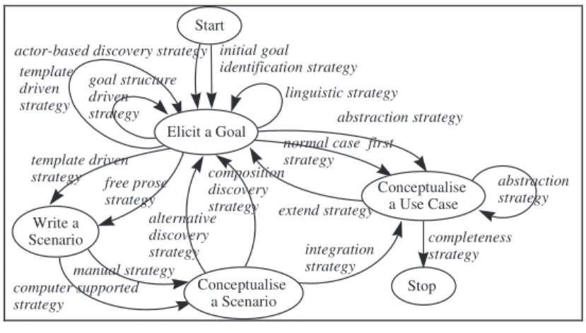
Map. A map is a labelled directed graph in which the nodes are the intentions and
the edges between intentions are the strategies (see [14] for more detail). The ordering of intentions and strategies is non-deterministic. The edges in the graph are directed and show which intentions can follow which one. Fig. 1 shows two examples of maps for OOSE and CREWS-L' Ecritoire methods respectively.
Start
actor-based discovery strategy
normal case first strategy extend strategy abstraction strategy completeness strategy Stop Conceptualise a Use Case abstraction strategy Elicit a Use Case
The OOSE Map
alternative discovery strategy composition discovery strategy goal structure driven
strategy Stop template driven strategy Conceptualise a Scenario template driven strategy free prose strategy computer supported strategy manual strategy completeness strategy linguistic strategy Write a Scenario initial goal identification strategy Elicit a Goal Start
The CREWS-L’Ecritoire Map
Fig. 1. The OOSE Use Case Model map and the CREWS-L’Ecritoire map
As shown in Fig.1, a map consists of a number of sections each of which is a triplet <ii,ij,sj> where ii is a source intention, ij is a target intention ant sij is a strategy
defining the way to go from the source to the target intention. There are two distinct intentions called Start and Stop that represent the intentions to start navigating in the map and to stop doing so. Thus, it can be seen that there are a number of paths in the graph from Start to Stop. We assume requirements engineering processes to be intention-oriented. At any moment, the requirements engineer has an intention, a goal in mind that he/she wants to fulfil. To take this characteristic into account the map identifies the set of intentions I that have to be achieved in order to solve the problem at hand. An intention is expressed as a natural language statement comprising a verb and several parameters, where each parameter plays a different role with respect to the verb [15]. For example, the OOSE [1], [16] map (Fig. 1) contains two intentions in addition to "Start" and "Stop" : "Elicit a Use Case" and "Conceptualise
a Use Case".
A strategy is an approach, a manner to achieve an intention. The strategy, as part of the triplet <ii,ij,sj>, characterises the flow from the source intention ii to the target
intention ij and the way ij can be achieved. The map identifies the set of strategies S
which allows to construct different paths in the map.
The specific manner in which an intention can be achieved is captured in a section of the map whereas the various sections having the same intention ii as a source and ij
as target show the different strategies that can be adopted for achieving ij when coming from ii. Similarly, there can be different sections having ii as source and ij1, ij2,
....ijn as targets. These show the different intentions that can be achieved after the
achievement of ii. The OOSE map is composed of six sections. The triplet <Elicit a
Use Case, Conceptualise a Use Case, Normal case first strategy> is an example of
The few strategies available in the OOSE map reflects the sequential nature of the process suggested by this method. There is for example, only one possibility to start the Use Case model development which is embedded in the section <Start, Elicit a
Use Case, Actor based strategy>. OOSE indeed, proposes to identify the actors of the
system as a means to identify use cases. The two sections : <Elicit a Goal,
Conceptualise a Use Case, Normal case first strategy> and <Elicit a Goal, Conceptualise a Use Case, Abstraction strategy> reflect the two OOSE possibilities :
to conceptualise each elicited use case by writing a normal case scenario at first and then, writing all alternative and exceptional scenarios or conceptualise a use case by reusing abstract use case descriptions. Then, when the intentions Elicit a Use Case is achieved, three sections can be selected : <Conceptualise a Use Case, Conceptualise
a Use Case, Abstraction strategy> which permits to conceptualise an abstract use case
from a set of concrete use cases, <Conceptualise a Use Case, Elicit a Use Case,
Extension strategy> which permits to identify an extension use case, and
<Conceptualise a Use Case, Stop, Completeness strategy> which terminates the development process if the obtained use case model is complete.
As shown in the CREWS-L’Ecritoire [6], [14] method map (Fig. 1), there are several flows between two intentions each corresponding to a specific strategy. For example, there are two strategies to "Write a Scenario" and two others to
"Conceptualise a Scenario". In this sense the map offers multi-thread flows. There
might also be several strategies from different intentions to reach some intention. For example, there are six strategies ("initial goal identification", "template driven",
"linguistic", "goal structure driven", "alternative discovery" and "composition discovery") coming from different intentions to the intention "Elicit a Goal". In this
sense the map offers multi-flow paths to achieve an intention.
The CREWS-L’Ecritoire method map represents a process to conceptualise a set of scenarios which describe functional system requirements. The complete set of scenarios obtained by this method covers the set of use cases that could be obtained when using the OOSE method. However as illustrated above, the CREWS-L’Ecritoire method map provides more strategies to achieve the process intentions and therefore, offers more flexibility in the scenario conceptualisation process. As depicted in Fig. 1, goal elicitation can be followed by the elicitation of another goal or by scenario writing. Three strategies: "linguistic", "goal structure driven" and "template
driven" are proposed to elicit a new goal. Scenario writing is supported by two
strategies, namely the "template driven strategy" and the "free prose strategy". The first proposes to write a scenario following a template whereas following the second strategy, the scenario author writes in full prose. Style and content guidelines are proposed in this case to support the scenario writing. Scenario writing can be followed by the scenario conceptualisation. The map proposes two possibilities to conceptualise scenarios : manually (manual strategy) or in a computer supported manner (computer supported strategy). Finally, scenario conceptualisation can be followed by the elicitation of new goals using two different strategies : "alternative
discovery strategy" and "composition discovery strategy", or the termination of the
development process by verifying the completeness of the obtained model "completeness strategy". The elicitation of new goals using "alternative discovery
strategy" permits to identify all alternative goals to a given one. The set of
corresponding scenarios contains one normal case scenario and all alternative and exceptional scenarios and therefore composes one use case. The elicitation of the new goals using "composition discovery strategy" permits to identify the complementary goals to a given one and therefore helps identifying the family of use cases for a given system.
To sum up, a map is a navigational structure in the sense that it allows the application engineer to determine a path from Start intention to Stop intention. The requirements engineer selects dynamically the next intention and /or strategy among the several possible ones offered by the map. The guidelines associated to the map help the engineer in his/her choice. Guidelines are presented in the next section.
Guidelines. Three kinds of guidelines are attached to the map: "Intention
Achievement Guideline" (IAG), "Intention Selection Guideline" (ISG) and "Strategy Selection Guideline" (SSG). An IAG helps to fulfil the intention selected by the
requirements engineer, whereas ISG and SSG help him/her to progress in the map and to select the right section. For every section <ii,ij,sij> in the map there exists one IAG.
The IAG supports the requirements engineer in the achievement of intention ij according to the strategy sij. This IAG corresponding to the section <Elicit a Use
Case, Conceptualise a Use Case, Normal case first strategy> from the OOSE map is
shown in Fig. 2. It provides an operational means to fulfil the intention
"Conceptualise a Use Case".
IAG: <(Use case objective), Conceptualise a use case with normal case first strategy>
<(Use case objective), Write a normal case scenario >
<(Use case objective , Normal case scenario ), Identify an exceptional scenario objective>*
<(Exceptional scenario objective), Write an exceptional scenario >
Fig. 2. The example of the intention selection guideline
A number of actions must be performed on the product under development to satisfy this intention. The IAG decomposes the initial intention into a set of sub-intentions which themselves may be decomposed till sub-intentions executable through actions on the product are reached. The structure of the guidelines is presented in [14]. It is based on the NATURE contextual approach [17] and its corresponding enactment mechanism [18].
Given two intentions ii, ij, there exists a SSG that determines the set of possible
strategies sij1, sij2, ..sijn applicable to ij and guides the selection of an sijk thereby leading
to the selection of the corresponding IAG. For example, given the two intentions
"Elicit a Goal" and "Write a Scenario" from Fig. 1, the SSG <(Goal), Progress to (Write a Scenario)> is shown in Fig. 3. This SSG presents to the requirements
engineer two strategies "template driven" and "free prose". The engineer picks up the strategy the most appropriate to the situation at hand. Thus, one of two possible sections in the map is selected. Since a unique IAG is associated with each section, the SSG determines this (Fig. 3).
SSG: <(Goal), Progress to (Write a Scenario)>
IAG: <(Goal),
Write a scenario with template driven strategy>
IAG: <(Goal), Write a scenario in free prose>
a1 a2
a1: Scenario author has to be a scenario writing expert, he/she has to fill a linguistic template. a2: Scenario author writs scenario in free prose. A set of style and content guidelines are provided to support scenario writing.
Fig. 3. The example of the strategy selection guideline
For a given intention ii, the ISG identifies the set of intentions (ij1, ij2,..., ijn) that can
be achieved in the next step and helps selecting the corresponding set of either IAGs or SSGs. The former is valid when there is only one section between ii and ij whereas
the latter occurs when there are several sections between ii and ij. For example, for the
intention "Elicit a Goal" (Fig. 1) the ISG identifies two possible next intentions
"Write a Scenario" and "Elicit a Goal". The ISG then determines whether there is
only one section between the source and the selected target intention or whether there are several sections. In the former case, the IAG associated with the section is used by the enactment mechanism to achieve the target intention. In the second case, the SSG is invoked to determine the strategy to be used in the situation which leads to the determination of an IAG and subsequent enactment.
ISG : <(Goal), Progress from (Elicit a Goal)>
SSG : <(Goal), Progress to (Write a Scenario)> SSG : <(Goal), Progress to (Elicit a Goal)>
Fig. 4. The example of the intention selection guideline
In our example, if the intention "Write a Scenario" is selected as target intention, the ISG determines that there are two sections between the source and target intentions. The SSG helps to decide which of these strategies shall be used. Thus, the corresponding IAG is determined and the intention "Write a Scenario" is achieved. If the intention "Elicit a Goal" is selected as target intention, the ISG determines that there are tree strategies allowing to fulfil this intention and the corresponding SSG is determined (Fig. 4).
2.2 Product Model
The product model is composed of a set of concepts which have properties and can be related through links. We shall use the following notations:
• A concept has name ci and a set of properties (pi1, pi2, ... pin). Thus it will be denoted
ci(pi1, pi2, ... pin). For sake of brevity, it is possible to denote a concept only by its
name ci. A set of concepts in the product model is described by C.
• The concepts in the product model are related through the links. A link has a label
lij , it is an association, a composition or an is-a link. The link is a part of the
between these two concepts. A set of the links in the product model is denoted by
L. Therefore, the product model is PM ⊆ C * C * L .
The product models of the OOSE method and of the CREWS-L' Ecritoire method are shown in Fig. 5 and Fig. 6 respectively using ER like notations. "Actor(Actor
Name, Description)" is an example of the concepts in the OOSE method. The link
between the "Actor" and the "Use Case Model" in OOSE product model is denoted
<Use Case Model, Actor, composed_of>.
Actor executes supports Use Case Model Scenario Concrete Use Case Abstract Use Case
#
composed ofcomposed of composed of extends
is a is a 1,N 1,N 0,N 2,N 1,1 1,1 1, N 1,1 1,1 1,N 0,N 0,N 0,N 1,1 Description
Normal Scenario Exeptional Scenario UseCase Description uses Use Case Objective ActorName Extension
Fig. 5. The OOSE Use Case product model.
OR Goal AND is a Normal Scenario ExceptionalScenario
Flow of Actions AtomicAction
composed of described by Agent from to 1,1 1,N 1,N 1,1 State initial state 1,1 1,1 1,N 1,N final state IdGoal Verbe Target Direction Way Beneficiary 1,N 1,N Action Requirement Chunk Scenario is a
Fig. 6 : The CREWS-L’Ecritoire product model.
The OOSE product model is centred on the concept of a use case. A use case is composed of a set of scenarios. It can be either concrete of abstract. It can also be extended by extensions which are themselves considered as use cases. The actor interacting with the system is related to the use case. Finally, the use case model is a collection of use cases with their associated actors.
The CREWS-L’Ecritoire product model is centred on the concept of a requirement chunk, i.e. the coupling of a goal to be achieved and a scenario explaining how the system will interact with the agents to achieve the goal. The description of a scenario is based on the notion of action and agent. The definition of a scenario in the
CREWS-L’Ecritoire product model is more detailed than the definition provided in the OOSE product model. We will see in the next section how this two product models can be integrated.
3 Method Integration
The integration of two methods consist in integrating their product and process models. We deal with these two aspects in turn. Clearly the goal in the example at hand is to take advantage of the authoring facilities and goal discovery strategies of the CREWS-L’Ecritoire approach which do not exist in the current OOSE method and vice versa, to import in the integrated method the OOSE abstraction and extend strategies which have no equivalent in CREWS-L’Ecritoire. Therefore, by integrating the two methods, the resulting method will represent an enhancement of each isolated one. We shall present in turn the operators for Product and Process integration. For sake of space, rules to check the consistency and completeness are not included.
3.1 Product Integration
Product Integration Operators. Let C be a set of concepts, L a set of links and PM a
product model, where PM ⊆ C* C * L. The set of operators is as follows:
• ADD_CONCEPT : PM *C → PM; ADD_CONCEPT(pm, ci) = pm ∪ ci. Adding a
concept consists in creating a new concept in the product model. Such an addition is sometimes required to make the integration of two concepts possible. Adding a concept in the product model requires to add at least one link connecting this concept to a concept of the product model.
• ADD_LINK : PM * C *C * L → PM; ADD_LINK(pm, ci, cj, lij) = pm ∪ <ci, cj, lij>.
This operator creates an association, a composition or an is-a link between two concepts of the product model. It is absolutely needed that the concepts which are going to play the role of the source and target of the link exist in the product model prior to the creation of the link.
• ADD_PROPERTY : PM * C → PM; ADD_PROPERTY(pm, c
i(pi1, pi2,..., pin), pik) =
pm ∪ ci(pi1, pi2,..., pik,..., pin). This operator permits to add a new property to an
existing concept.
• DELETE_CONCEPT : PM * C → PM; DELETE_CONCEPT(pm, c
i(pi1, pi2,..., pin))
= pm \ ci(pi1, pi2,..., pin). This operator removes a concept ci(pi1, pi2,..., pin) from the
schema. Deleting a concept consists in deleting the concept ci and all its properties
pi1, pi2,..., pin. The concept can be removed from the product model only if all links
which were connecting them concept to other concepts have been removed. • DELETE_LINK : PM * C * C * L → PM; DELETE_LINK(pm, <c
i, cj, lij> ) = pm\
<ci, cj, lij>. This operator removes a relationship <ci, cj, lij> from the product
model. If one of the related concepts does not have any more links to other concepts, this concept must be removed from the product model or another link must be added to relate this concept to the rest of the schema.
• DELETE_PROPERTY : PM * C → PM; DELETE_PROPERTY(pm, c
i (pi1, pi2,...,
pik,..., pin), pik ) = pm ∪ ci (pi1, pi2,..., pin). This operator removes a property pik of a
concept ci.
• OBJECTIFY : PM * C * C* L * C *L * L → PM; OBJECTIFY(pm, <c
i, cj, lij>, ck,
lik, lkj) = pm \ <ci, cj, lij> ∪ <ci, ck, lik> ∪ <ck, cj, lkj>. The OBJECTIFY operator
transforms a relationship <ci, cj, lij> into an concept ck and two new links
connecting this concept with the two other concepts.
• RENAME_CONCEPT: PM * C → PM; RENAME_CONCEPT(pm, c i, ci 1 ) = pm | ci = ci 1
. This operator changes the name of a concept. This operator is useful in the integration of two overlapping product models.
• RENAME_LINK: PM * C * C * L * L → PM; RENAME_LINK(pm, <c i, cj, lij>, lij 1 ) = pm ∪ <ci, cj, lij = lij 1
>. This operator changes the name of a link. If two concepts
are related by two links having the same name, one of the links must be renamed. • RENAME_PROPERTY: PM * C → PM; RENAME_PROPERTY(pm, c i(pi1, pi2,..., pik,..., pin), pik 1 ) = pm ∪ ci (pi1, pi2,..., pik= pik 1
,..., pin). This operator changes the name
of a property of a concept ci from pik i to pik 1
. If the integrated concept has two properties with the same name and different semantics, one of these properties must be renamed. If these properties have the same name and the same semantic one of these properties must be removed.
• SPECIALISE : PM * C * C * C → PM; SPECIALISE(pm, c
i, ck, cl) = pm ∪ ck ∪ cl
∪ <c
k, ci, is-a> ∪ <cl, ci, is-a>. This operator specialises the concept ci into two
new concepts ck and cl. The two concepts ck and cl that play the role of sub-type for
ci are created first and then, the is-a links between ci and ck and between ci and cl
are created. In this definition we make the hypothesis that the concepts ck and cl do
not exist yet in the product model.
• GENERALISE : PM * C * C * C → PM; GENERALISE(pm, c
i, cj, ck) = pm ∪ ck ∪
<ci, ck, is-a> ∪ <cj, ck, is-a>. This operator permits to generalise two concepts ci
and cj. into a new concept ck. A new concept ck is created first and then, two Is-A
links are created. One of them connects ci with the generalised concept ck and the
second one connects cj with the generalised concept ck. Common properties of ci and cj are deleted from these concepts and added to the concept ck.
• MERGE: PM * C * PM * C *PM * C → PM; MERGE(pm
1,c1, pm2,c2, pm3,c3) =
pm3 ∪ c3. The MERGE operator integrates two concepts c1 and c2 from different
product models pm1 and pm2 respectively into a third one called c3 in the integrated
product model pm3. The concepts c1 and c2 must have the same name prior to their integration. The properties and the links of each merged concept are kept in the new concept.
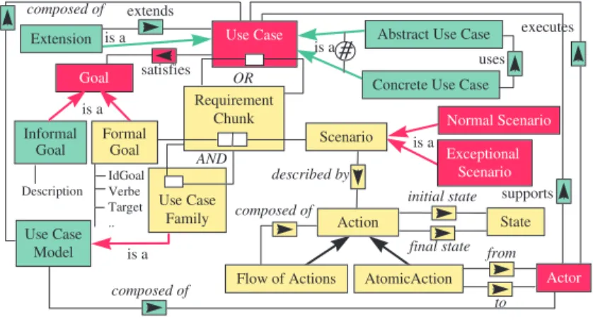
Example. The application of the product integration operators to the integration of
OOSE and CREWS - L’Ecritoire product models is shown in Fig. 7. Some of the concepts of the integrated product model are directly derived from the initial product models, while others are the result of the application of the operators. We comment some examples of concept integration in the following.
Use Case Family OR AND is a Normal Scenario Exceptional Scenario composed of described by Actor from to Concrete Use Case
#
extends is a uses Informal Goal Goal Use Case Model satisfies Description is a is a executes supports is a composed of composed of State initial state final state IdGoal Verbe Target .. Use Case Requirement Chunk Formal Goal Scenario ActionAbstract Use Case
Flow of Actions AtomicAction Extension
Fig. 7. The integrated product model.
The "Actor" concept in the OOSE product model (Fig. 5) and the "Agent" concept in the CREWS-L' Ecritoire product model (Fig. 6) have the same semantic but different names. We can rename one of these concepts and then merge them into a new concept in the product model of the integrated method (IM).
• RENAME_CONCEPT (CREWS-L'Ecritoire, Agent, Actor) • MERGE((CREWS-L'Ecritoire, Actor), (OOSE, Actor), (IM, Actor))
The concept of "Use case" exists only in the OOSE method. However the set of scenarios related through "OR" relationships in the CREWS-L’Ecritoire approach is equivalent. The operator OBJECTIFY allows us to transform the "OR" relationship between two "RC" concepts into a new concept called "Use Case".
• OBJECTIFY(CREWS-L'Ecritoire, <RC, RC, OR>, Use Case)
Therefore, the "Use Case" concept in the integrated method is obtained by merging the "Use Case" concept from the OOSE method and the "Use Case" concept from the CREWS-L’Ecritoire method.
• MERGE((CREWS-L'Ecritoire, Use Case), (OOSE, Use Case), (IM, Use Case)) A similar reasoning than the one applied above to the CREWS-L' Ecritoire "OR"
relationship leads to the reification of the "AND" relationship as the concept of "Use
case Family". The transformation is as follows :
• OBJECTIFY(CREWS-L'Ecritoire, <RC, RC, AND>, Use Case Family)
Finally, the concept of a "Use Case Model" is part of the OOSE method but does not exist explicitly in the CREWS-L’Ecritoire product model. However there is a relationship between the use case model and the use case family which leads to add a new Is-A link in the integrated model between the concept "Use Case Model" and the concept "Use Case Family" .
• ADD_LINK(IM, < Use case Family, Use Case Model, is-a>)
The concept of "Scenario" belongs to both product models. Merging the two concepts leads to create a new concept whose properties are the union of the properties of both concepts. All the links relating these concepts with the rest of the
product model are kept in the new product model. The same operation is applied on the concepts "Normal Scenario" and "Exceptional Scenario".
• MERGE((CREWS-L' Ecritoire, Scenario), (OOSE, Scenario), (IM, Scenario)) However, the analysis of the properties and the relationships of the obtained
"Scenario" concept shows that the role of the "Description" property on the one hand
and the link "described-by" with the concept "Action" and the links "initial-state", and "final-state" with the concept "State" on the other hand, have the same meaning. As a matter of fact, in the CREWS-L' Ecritoire method, a scenario has a set of actions and a final and an initial state. Thus, keeping all these features in the integrated concept of scenario would introduce redundancy. This suggested to us to delete the property "Description" from the "Scenario" concept.
• DELETE_PROPERTY (IM, Scenario (Description), Description)
Finally, the notion of "Goal" in the CREWS-L' Ecritoire method represents the objective of the use case in a similar way the property "Objective" in the OOSE method does. Therefore, the "Objective" must be replaced by the concept "Informal
Goal" because its structure is different from the "Goal" structure in the
CREWS-L' Ecritoire method. These two concepts cannot be merged into one single concept. To avoid ambiguities, it was decided to rename the concept "Goal" into "Formal Goal" and then, to generalise the concepts "Formal Goal" and "Informal Goal" into the concept "Goal".
• ADD_CONCEPT (IM, Informal Goal)
• ADD_LINK (IM, <Use Case, Informal Goal, Has>) • RENAME_CONCEPT (IM, Goal, Formal Goal)
• GENERALISE (IM, Informal Goal, Formal Goal, Goal)
2.2 Process Integration
Process Integration Operators. The integration of the process models consists in
integrating their maps and adapting the corresponding guidelines accordingly. Let I be a set of intentions and S a set of strategies. The map is Map ⊆ I * I * S . The set of operators for integrating maps is as follows:
• RENAME_INTENTION : Map * I * I → Map; RENAME_INTENTION(m, ii, ij) =
m | ii = ij
• RENAME_SECTION : Map* I * I * S * S → Map; RENAME_ SECTION(m, <ii, ij,
sij>, sij 1
) = m | <ii, ij, sij = sij 1
>
These two operators allow to unify the terminology of two overlapping maps by renaming some intentions or strategies of each map. Two intentions from different maps having the same target product must be unified; however, the two intentions must have the same name before their integration. The RENAME_INTENTION operator allows to choose the more appropriate intention name. The same kind of operation must be performed on two sections from different maps having the same source and same target intentions. If the corresponding IAGs have the same situations (input products) and produce the same target products in the same manner, these sections shall be unified and renamed.
• ADD_SECTION : Map * I * I * S → Map; ADD_ SECTION(m, i
i, ij, sij) = m ∪ <ii,
ij, sij>. This operator allows us to add a new section in the map. More precisely, it
permits to introduce a new strategy between two existing intentions. The addition of a new section consists in adding a new IAG which defines a new way to achieve the target intention following the new strategy. If there are already several sections having the same input and output intentions, the SSG allowing to select one of these sections is modified accordingly. In the contrary, if the added section is the only one between these two intentions, the ISG of the source intention must be modified.
• REMOVE_ SECTION: Map * I * I * S → Map; REMOVE_ SECTION(m, <i
i, ij,
sij>) = m \ <ii, ij, sij>. This operator permits to delete one section from the map if
its strategy is not relevant in the integrated map or if this section will be replaced by a more appropriate one. The removing of the section from the map consists in removing the corresponding IAG. If there are several sections having the same input and output intentions, the corresponding SSG must be modified. If the removed strategy was the only strategy available between these two intentions, the corresponding ISG must be modified.
• ADD_INTENTION : Map * I → Map; ADD_INTENTION(m, i) = m ∪ i. This operator permits to add a new intention in the map. The addition of a new intention in the map implies to add at least one input and one output strategy. Therefore, two sections at least must be added in the map.
• REMOVE_INTENTION : Map * I → Map; REMOVE_INTENTION(m, i) = m \ i. This operator allows to remove an intention from the integrated map if this intention is not appropriate or if it is replaced by another one. As the intention might be connected to several other intentions of the map, this operator can be applied only if all sections connecting this intention with other intentions have been removed before. The ISGs concerning this intention are modified.
• MERGE_SECTION : Map * I *I * S * Map * I *I * S * Map * I *I * S → Map;
MERGE_SECTION (m1, <i1i, i1j, s1ij>, m2, <i2i, i2j, s2ij>, m3, <i3i, i3j, s3ij>) = m3 ∪
<i3i, i3j, s3ij>. This operator allows to merge two sections originating from different
maps into one section of the integrated map. The merge of two sections is possible if these sections have the same input and the same output intentions and if the strategies have the same name. The merge of two sections consists in selecting the more complete IAG or to merge the two IAGs into an integrated IAG. In the first case one of two IAGs is selected, in the second case a new IAG is defined. • MERGE_INTENTION: Map * I * Map * I * Map * I → Map; MERGE_
INTENTION(m1, i1, m2, i2, m3, i3) = m3 ∪ i3. This operator allows to merge two
intentions from different maps having the same name. All the sections having this intention as source or target intention are preserved and the corresponding ISG is modified. The both MERGE operators are especially useful in the integration of two overlapping maps. They allow to integrate two maps without the addition of a new intention or a new section.
• SPLIT_SECTION : Map * I * I * S * S * S → Map; SPLIT_SECTION(m, <i
i, ij, sij>, sij 1 , sij 2 ) = m \ <ii, ij, sij> ∪ <ii, ij, sij 1 > ∪ <ii, ij, sij 2
>. This operator allows to
the strategy of this section provides two different tactics to satisfy the target intention. The two obtained sections have the same source intention and the same target intention. The IAG of this section is decomposed into two IAGs and the SSG is modified or a new SSG is created if it does not existed before.
It shall be noticed that the presented lists of operators for both product and process models integration might be not exhaustive ones.
Example. The application of the operators for integration of the OOSE map and the
CREWS-L‘Ecritoire map is presented in Fig. 8.
alternative discovery strategy composition discovery strategy goal structure driven strategy template driven strategy template driven strategy free prose
strategy computer supported strategy manual strategy linguistic strategy Write a Scenario initial goal identification strategy actor-based discovery strategy
normal case first strategy extend strategy abstraction strategy completeness strategy Stop Conceptualise a Use Case abstraction strategy Elicit a Goal Start Conceptualise a Scenario integration strategy
Fig. 8. The integrated map
In the first step of the integration process an effort shall be done to unify the terminology used in the two maps. We need to verify if there are two concepts (intentions or/and strategies) in the different maps having the same name, or similar semantic and thus rename one of the two concepts. We need also to unify the names of concepts having the same semantics but different names. In the case at hand, the intentions "Elicit Goal" from the CREWS-L‘Ecritoire map and "Elicit Use Case" from the OOSE map have different names but are similar in nature. The two intentions refer in fact to the functionality' s that the system must provide to its users. The latter emphasises the term "use case" whereas the former prefers to put the light of the "goal" corresponding to the function. Thus, we rename the intention "Elicit a
Use Case" of the OOSE map as "Elicit a Goal" and then apply the MERGE
operator :
• RENAME_INTENTION(OOSE, Elicit Use case, Elicit Goal )
• MERGE_INTENTION((OOSE, Elicit Goal), (CREWS-L' Ecritoire, Elicit Goal),
(IM, Elicit Goal))
The intentions "Start" and "Stop" should be also merged in the integrated map: • MERGE_INTENTION((OOSE, Start), (CREWS-L' Ecitoire, Start), (IM, Start)) • MERGE_INTENTION ((OOSE, Stop), (CREWS-L' Ecitoire, Stop), (IM, Stop))
The intention obtained by applying the operator MERGE_INTENTION preserves all sections from the OOSE map and all sections from the CREWS-L' Ecritoire map having the same intention as a source intention. A new ISG is constructed for each
application of this operator. For example, the merge of "Elicit a Goal" intentions implies the construction of a new ISG which contains the corresponding ISG from the CREWS-L' Ecritoire map and is completed by the progression to the use case conceptualisation, which corresponds to the sections coming from the OOSE map.
The merge of the "Start" intentions does not lead to a new ISG, because in the two maps, the sections from "Start" have the same target intention, namely "Elicit a
Goal". In this case a new SSG is constructed guiding the selection of one of the two
strategies (one strategy from the OOSE map and one strategy of CREWS-L' Ecritoire map).
In the current situation, the integrated map proposes two different results : a set of conceptualised scenarios and a set of use cases. In the integrated map we must obtain only one result. The addition of a new section allowing to integrate a set of scenarios into a use case can be the solution of our problem. Therefore, we add a new section with an "integration strategy" which connects the intention "Conceptualise a
Scenario" with the intention "Conceptualise a Use Case". This section performs the
integration of scenarios obtained using the CREWS-L’Ecritoire process into use cases equivalent to the use cases obtained using the OOSE process. The corresponding IAG providing the guidelines to integrate a set of scenarios into a use case must be defined. Moreover, the section <Conceptualise a Scenario, Stop, Completeness
strategy> must be removed from the integrated map and the ISG defining the progress from the intention "Conceptualise a Scenario" is modified : the possibility to progress to the "Stop" intention is removed and the possibility to flow to the intention
"Conceptualise a Use Case" is added. The following operators are applied on the
integrated map :
• ADD_SECTION (IM, <Conceptualise a Scenario, Conceptualise a Use Case,
Integration strategy>)
• REMOVE_ SECTION (IM, <Conceptualise a Scenario, Conceptualise a Use Case,
Completeness strategy>)
As the objective of the integration of two maps is to enhance the OOSE process, the section <Elicit a Goal, Conceptualise a Use Case, Normal case first strategy> can be removed from the resulting map. This section is replaced by the CREWS-L’Ecritoire <goal elicitation, scenario conceptualisation> process which provides richer guidelines than the IAG of the section <Elicit a Goal, Conceptualise a Use
Case, Normal case first strategy>.
• REMOVE_ SECTION(IM, <Elicit a Goal, Conceptualise a Use Case, Normal case
first strategy>)
The application of this operator implies to delete the corresponding SSG because there is now only one section coming from the intention "Elicit Goal" to the intention
"Conceptualise a Use Case".
Discussion on the Map Integration. The representation of the process model by a
map and a set of guidelines allows us to provide a strategic view of processes. This view tells what can be achieved (the intention) and which strategy can be employed to achieve it. We separate the strategic aspect from the tactical aspect by representing the former in the method map and embodying the latter in the guidelines. By
associating the guidelines with the map, a smooth integration of the strategic and the tactical aspects is achieved.
Traditional stepwise process models have difficulty to handle the dynamically changing situation of a process. The map contributes to solve this problem by constructing the process model dynamically. Therefore, it is easier to represent a process allowing several different ways to develop the product by a map and a set of guidelines than by a set of steps. In the former approach, each step can be performed in several different manners. In the map it is represented by an intention to achieve and a set of strategies. Each strategy describes a different manner to achieve the intention.
Integrating maps is easier than integrating the stepwise process models, especially in the case where the process models overlap. The enhancement of a stepwise process model by another one requires to construct a new process model. On the contrary, the enhancement of a map by an another map does not require to modify all guidelines. Only the guidelines involved in the overlapping parts are modified.
3
Conclusion and Future Work
In this paper we have proposed and illustrated an approach for integrating a scenario-based technique into an existing industrial method. The approach is built upon : − a set of operators to integrate the product aspects of the two methods on one hand,
and to integrate their process aspects in the other hand and,
− a set of rules to check whether if the integrated method is consistent or not. The motivation for developing such an approach was twofold : first, scenarios have proven useful to requirements engineering but cannot be used in isolation and, secondly, existing methods which cover the entire system life cycle might be enhanced by integrating scenario-based techniques in the requirements engineering step. The paper has shown how to enhance the use case model construction of the OOSE method by integrating the goal discovery and scenario authoring features of the CREWS-L' Ecritoire approach. Vice-versa the rest of the analysis and design process of the OOSE method remains usable.
The approach needs to be validated and improved in other cases. Our goal is to do so in the first place, by integrating the four CREWS scenario-based techniques one with the other and with the OOSE method. We are currently working on the development of a computerised support for facilitating such an integration and to connect this facility with the method base query facilities presented in [19].
Acknowledgements : the authors would like to thank the CREWS project members for their contributions to the development of the ideas presented in the paper.
References
1. I. Jacobson, M. Christerson, P. Jonsson and G. Oevergaard, Object Oriented Software
2. Rational Software Corporation, "Unified Modelling Language version 1.1". Available at http://www.rational.com/uml/documentation.html, 1998.
3. J. Rumbaugh, M. Blaha, W. Premerlani, F. Eddy, and W. Lorensen, Object-Oriented
Modeling and Design. Prentice Hall, 1991.
4. P. Haumer, K. Pohl, K. Weidenhaupt, Requirements Elicitation and Validation with real
world scenes. IEEE Transactions on Software Engineering, Vol. 24, N°. 12, Special Issue on Scenario Management, December. 1998.
5. C. Rolland, C. Ben Achour, Guiding the construction of textual use case specifications. Data & Knowledge Engineering Journal Vol. 25 N° 1, pp. 125-160, (ed. P. Chen, R.P. van de Riet) North Holland, Elsevier Science Publishers. March 1997.
6. C. Rolland, C. Souveyet, C. Ben Achour, Guiding Goal Modelling Using Scenarios. IEEE Transactions on Software Engineering, special issue on Scenario Management, 1998. 7. A. G. Sutcliffe, Scenario-based Requirements Analysis. Requirements Engineering Journal,
Vol (3) N° 1, (ed. P. Loucopoulos, C. Potts), Springer Verlag. 1998.
8. E. Dubois, P. Heymans, Scenario-Based Techniques for supporting the Elaboration and the
Validation of Formal Requirements, Submitted to RE Journal, 1998.
9. M. Saeki, K. Wen-yin, Specifying Software Specification and Design Methods. Proceedings of Conference on Advanced Information Systems Engineering, CAISE' 94, Lecture Notes in Computer Science 811, Springer Verlag, pp. 353-366, Berlin, 1994.
10.C. Rolland, N. Prakash, A proposal for Context-Specific Method Engineering, IFIP TC8 Working Conference on Method Engineering, Atlanta, Gerorgie, USA, 1996.
11.S. Brinkkemper, M. Saeki, F. Harmsen, Assembly Techniques for Method Engineering. Proceedings of the 10th
Conference on Advanced Information Systems Engineering, CAiSE’98. Pisa Italy, 8 -12 June, 1998.
12.X. Song, A Framework for Understanding the Integration of Design Methodologies. In: ACM SIGSOFT Software Engineering Notes, Vol. 20, N°1, pp. 46-54, 1995.
13.M. Bouzeghoub, I. Comyn, View Integration by Semantic Unification and Transformation
of Data Structures, Proceedings of the Conference on Requirements Engineering, RE' 90, Lausanne, 1990.
14.C. Rolland, N. Prakash, A. Benjamen, A multi-model view of process modelling. To appear in the RE journal, 1999.
15.N. Prat, Goal formalisation and classification for requirements engineering. Proceedings of the Third International Workshop on Requirements Engineering: Foundations of Software Quality REFSQ’97, Barcelona, pp. 145 -156, June 1997.
16.I. Jacobson, The use case construct in object-oriented software Engineering. In ‘Scenario-based design: envisioning work and technology in system development’, John M. Carroll (ed.), John Wiley and Sons, 309-336, 1995.
17.G. Grosz, C. Rolland, S. Schwer, C. Souveyet, V. Plihon, S. Si-Said, C. Ben Achour, C. Gnaho, Modelling and Engineering the Requirements Engineering Process : an overview of
the NATURE approach. Requirements Engineering Journal 2, pp. 115-131, 1997.
18.S. Si-Said, C. Rolland, G. Grosz, MENTOR :A Computer Aided Requirements Engineering
Environment. Proceedings of CAiSE' 96, Crete, GREECE, May 1996.
19.C. Rolland, V. Plihon, J. Ralyté, Specifying the reuse context of scenario method chunks. Proceedings of the 10th
Conference on Advanced Information Systems Engineering, CAiSE’98. Pisa Italy, 8 -12 June, 1998.