HAL Id: hal-02468094
https://hal.archives-ouvertes.fr/hal-02468094
Submitted on 7 Feb 2020HAL is a multi-disciplinary open access archive for the deposit and dissemination of sci-entific research documents, whether they are pub-lished or not. The documents may come from teaching and research institutions in France or abroad, or from public or private research centers.
L’archive ouverte pluridisciplinaire HAL, est destinée au dépôt et à la diffusion de documents scientifiques de niveau recherche, publiés ou non, émanant des établissements d’enseignement et de recherche français ou étrangers, des laboratoires publics ou privés.
Modelling of a passive hydraulic lock concept for the
Mitigation Transfer Tubes in a SFR core
Michel Belliard, Sophie Bajard, Thierry Cadiou
To cite this version:
Michel Belliard, Sophie Bajard, Thierry Cadiou. Modelling of a passive hydraulic lock concept for the Mitigation Transfer Tubes in a SFR core. Nuclear Engineering and Design, Elsevier, In press, pp.110500. �10.1016/j.nucengdes.2019.110500�. �hal-02468094�
Modelling of a Passive Hydraulic Lock concept for the Mitigation Transfer Tubes in
a SFR core
Michel BELLIARD, Sophie BAJARD, Thierry CADIOU CEA, DEN, DER, SESI, F-13108, Saint Paul lez Durance, France
thierry.cadiou@cea.fr
ABSTRACT
To improve the safety of the integrated Sodium-cooled Fast Reactor, we present an original safety complementary device to prevent or mitigate the consequences of a hypothetical severe accident consecutive to a loss of reactor cooling sequence. This device is set by empty transfer tubes, in place of some fuel sub-assemblies present in the reactor core, using an innovative passive hydraulic lock. It is based on the concept of hydraulic diode controlled by the flowrate of primary pumps. This system is dedicated to provide an easy way to discharge corium towards the core catcher in the hypothetical case of severe accident. In bonus, concerning the prevention of severe accident, it opens a direct flow path between the hot pool, equipped with decay heat removal exchangers, and the cold pool. This can lead to an easier passage of colder sodium towards the cold pool to promote core cooling by natural convection in case of the loss of the primary flow. In this paper, we focus on the assessment of the hydraulic lock function and of the small magnitudes of the perturbations induced by our device on the thermal-hydraulic behavior of the reactor during normal operations. Through an analytical analysis and an up-scaling numerical approach, ranging from the local scale (CFD) to the system one, we claim that the lock function is kept during the normal situations at various power regimes. The leak flow represents no more than 1% of the primary pump flow. In addition, no important reactor thermal-hydraulic perturbation is brought by adding transfer tubes in the core. This is true for normal steady states, whatever the power is, but also for a full-power loss of forced flow accidental transient leading to the natural convection cooling.
KEYWORDS
Sodium-cooled Fast Reactor, thermal-hydraulics in sub-assembly, PHYLOCK, up-scaling, CFD, component scale, system scale
1. Introduction
In a typical Sodium-cooled Fast Reactor (SFR) with an integrated concept [1], the primary circuit is entirely inside the main vessel (i.e. no loop), cf. Fig. 1. The integrated SFR design has some intrinsic advantages from the point of view of the safety. In particular, the thermal inertia of the coolant is large and the natural convection of the primary sodium fluid is facilitated thanks to the elevation differences between the heat source (core) and the cold sources (Intermediate Heat eXchangers: IHX). However, this advantage can be nullified if the IHX are unavailable. In order to cool down the primary sodium fluid heated in the core, safety exchangers as the Decay Heat Removal (DHR) are therefore needed. In case of a hypothetical core melt due to loss of the DHR heat exchangers, complementary safety devices, denoted M-TT for Mitigation Transfer Tubes, will favor transport of corium to the core catcher to mitigate the consequences of this kind of accident [2]. It is proposed to substitute empty tubes, open at both ends, to some fuel sub-assemblies present in the reactor core. It has the advantage of providing a direct flow path for corium towards the core catcher. Their efficiency has been proved in a recent study [3] in which it has been evaluated that thanks to a fast draining of a part of the fuel from the core region through the M-TT, the mechanical energy release is one order of magnitude lower with tubes than without.
In this paper, we focus on the compatibility between the M-TT device and the reactor primary circuit behavior. Moreover, concerning the prevention of a severe accident, this device can be used to promote the reactor core cooling by natural convection. In this situation, the classical hydraulic path for the DHR cooled sodium from hot pool to cold pool is through the IHX. As the IHX inlet is at a higher elevation than the DHR outlet, the path between the two pools is facilitated by the M-TT.
Fig. 1 Scheme of the primary circuit of a SFR with M-TT
In case of an eventual penetration from the reactor cover non-reactive gas, empty tubes offer the advantage to avoid or minimize gas retention. Moreover, it let the possibility to wash the M-TT sub-assemblies. Obviously, the M-TT device must work as a lock and induce only small perturbations on the hydraulic behavior of the reactor during normal operations from stand-by to full power state. Hence, no fluid must be allowed to flow between the hot and cold pools, unless a small by-pass flow. For this goal, these empty tubes are equipped with an innovative device, designated under the name of PHYLOCK [4], and based on the concept of hydraulic diode.
The paper is organized in a up-scaling approach as follows. First, the M-TT PHYLOCK concept is described and analytically analysed in Sections 2 and 3. This analysis is supported in Section 4 by a numerical study based on computational fluid dynamics at the local scale. It gives up-scaling elements to construct a stand-alone 3D-model at the component scale using a thermal-hydraulic system code in Section 5. In particular, the hypothetical gas retention issue in the M-TT is numerically analyzed. Then, Section 6 presents the integration of this M-TT 3D-model into a full reactor model at the system scale using the same code. The impact of the M-TT on eventual reactor thermal-hydraulic perturbations is studied for various steady-states regimes as well as for a loss of primary flow transient. Finally, some conclusions and perspectives are given.
2. M-TT hydraulic lock concept
As presented in the introduction, there are four functional requirements of the transfer tubes:
- prevent the severe accidents by providing a direct path between hot and cold pools and a more efficient natural-convection core cooling,
- mitigate a hypothetical severe accident ensuring the rapid flow of the corium to the core catcher, - ensure compatibility with the core thermal-hydraulics anytime in normal operation,
It is important to note that there is a difference of ∆ℎ ≈ 1.6 𝑚 between the hot and cold pools free levels for the nominal steady state (cf. Fig. 2). This elevation difference is related to the pressure loss at the IHX depending on the primary mass flow. Consequently, for a given axial elevation, the hot pool is over pressurized relatively to the cold pool. Then, at steady state:
𝑃𝑐 = 𝑃ℎ+ 𝜌 ∙ 𝑔 ∙ 𝐻𝑇𝑇− 𝜌 ∙ 𝑔 ∙ ∆ℎ (1)
𝐻𝑇𝑇: total height of the tube (m) 𝑃ℎ : upper pressure of the tube (Pa)
𝑃𝑐 : lower pressure of the tube (Pa) 𝜌 : sodium density (kg/m3)
Then, the difference of total pressure ∆𝑃, between the two extremities of the tube, is equal to:
∆𝑃 = (𝑃ℎ− 𝑃𝑐) = 𝜌 ∙ 𝑔 ∙ (∆ℎ − 𝐻𝑇𝑇) (2)
Alternatively, the difference of reduced pressure ∆𝑃𝑟 (with gravity terms) is equal to:
∆𝑃𝑟 = (𝑃ℎ− 𝑃𝑐) + 𝜌 ∙ 𝑔 ∙ (𝐻𝑇𝑇− 0) = 𝜌 ∙ 𝑔 ∙ ∆ℎ (3)
Fig. 2 Reactor vessel with the transfer tube in normal operation (left) and zoom on the tube (right)
Due to this pressure difference P, sodium should flow downwards. To avoid this, the transfer tubes are equipped with one or more injectors, fed by the primary pumps, ensuring the tightness between the hot and cold pools in operating situation (cf. Fig. 2 and Fig. 3). Conversely, in case of a primary pump failure, the sodium supply of the injectors is instantaneously stopped. Then this seal disappears allowing the direct passage of sodium between the hot pool and the cold pool. In general, an injector system is used to transfer fluid from a low-pressure region to a higher one. In this case, the injector system of the tube is designed to stop the sodium flow coming from the hot pool to the cold pool.
Fig. 3 Principle of the Transfer Tube
The presence of injectors induces some untreated issues for the moment such as:
- the cross-section in the tube is locally reduced by the presence of the injectors (potentially up to 30%), which could possibly limit the passage of the corium,
- a possible risk of cavitation in the injector nozzles remains to be studied,
- the hypothetical accumulation and retention of sodium dissolved gas in the M-TT,
- an eventual thermal cracking of the hexagonal tube could appear at the equilibrium plane if no thermal diffusion is existing between hot and cold sodium.
3. Analytical approach
The injector is said to be in equilibrium when the flowrate in the upper part of the through tube is zero. In non equilibrium, there is a residual flow going upwards or downwards, depending on the injector flowrate.
3.1 Equilibrium state
The domain of study chosen for the analytical approach is shown in Fig. 4. The injector, schematically represented by the red arrow, is positioned in the lower part of the M-TT. Due to the pressure difference P between the hot pool above and the cold pool below, sodium should flow downwards. Thanks to the flowrate injected to counteract it, the downward flow of hot sodium is totally stopped whereas the injected sodium flow is reversed.
Fig. 4 Principle of the injector
3.1.1 Mass conservation equation
At the equilibrium, the upward hot sodium is stopped and the injected flow is totally transferred into the lower part of the tube. In terms of flowrate, the injected sodium will totally go downwards at equilibrium, whereas the hot sodium from the hot pool will be stopped.
𝑄𝑖𝑛𝑗 = 𝜌 ∙ 𝑆𝑖𝑛𝑗∙ 𝑣𝑖𝑛𝑗 = 𝜌 ∙ 𝑆𝑜𝑢𝑡∙ 𝑣𝑜𝑢𝑡 (4)
𝑣𝑖𝑛𝑗 : injector velocity (m/s)
𝑆𝑖𝑛𝑗 : section of the injector nozzle (m2) 𝑄𝑖𝑛𝑗 : injector flowrate (kg/s)
𝑣𝑜𝑢𝑡 : downwards sodium velocity (m/s) 𝑆𝑜𝑢𝑡 : section of the tube (m2)
𝜌 : sodium density (kg/m3
)
3.1.2 Momentum balance equation
For a steady-state flow, the momentum conservation applied to a domain delimited by surfaces leads to the following equation, where 𝒏 is the outside oriented normal vector [5].
∑ 𝜌 ∙ 𝑣2∙ 𝑆 ∙ (𝒌 ∙ 𝒏) + 𝑃 ∙ 𝑆 ∙ (𝒌 ∙ 𝒏)
𝑒𝑥𝑡𝑒𝑟𝑛𝑎𝑙 𝑠𝑢𝑟𝑓𝑎𝑐𝑒 = −𝜌 ∙ 𝑔 ∙ (𝒌 ∙ 𝒏) + 𝑭 (5)
𝑣: velocity on external surface (m/s) 𝒌 : unitary vector along the z axis (-) 𝒏 : unitary vector normal to the surface (-) 𝑃: pressure on external surface (Pa)
𝑭 : Force exerted by the fluid on the surrounding surface (N)
Applied to the injector domain, since no external force is exerted on the fluid, the previous equation is rewritten for the M-TT flow reversal region (cf. Fig. 4) as follows:
𝜌 ∙ 𝑆𝑖𝑛𝑗∙ 𝑣𝑖𝑛𝑗2 + 𝜌 ∙ 𝑆
𝑜𝑢𝑡∙ 𝑣𝑜𝑢𝑡2 = 𝜌 ∙ 𝑔 ∙ 𝐻 ∙ 𝑆𝑜𝑢𝑡+ 𝑃𝑡∙ 𝑆𝑜𝑢𝑡− (𝑃𝑜𝑢𝑡∙ 𝑆𝑜𝑢𝑡+ 𝑃𝑖𝑛𝑗∙ 𝑆𝑖𝑛𝑗) (6)
𝐻: height of the flow reversal region (m)
𝑃𝑡 : upper pressure of the flow reversal region (Pa) 𝑃𝑜𝑢𝑡 : lower pressure of the flow reversal region (Pa) 𝑃𝑖𝑛𝑗: pressure at the injector nozzle (Pa)
If we assume that the pressures at the lower and upper sides of the flow reversal region can be approximated by the hydrostatic pressures 𝑃𝑡 ≈ 𝑃ℎ+ 𝜌 ∙ 𝑔 ∙ 𝐻𝑡 and 𝑃𝑜𝑢𝑡 ≈ 𝑃𝑐− 𝜌 ∙ 𝑔 ∙ 𝐻𝑜𝑢𝑡 , and that
Sinj
Sout≪ 1, the momentum balance can be rewritten:
𝜌 ∙ 𝑆𝑖𝑛𝑗∙ 𝑣𝑖𝑛𝑗2 + 𝜌 ∙ 𝑆𝑜𝑢𝑡∙ 𝑣𝑜𝑢𝑡2 = 𝜌 ∙ 𝑔 ∙ 𝐻𝑇𝑇∙ 𝑆𝑜𝑢𝑡+ 𝑃ℎ∙ 𝑆𝑜𝑢𝑡− (𝑃𝑐∙ 𝑆𝑜𝑢𝑡+ 𝑃𝑖𝑛𝑗∙ 𝑆𝑖𝑛𝑗) (7)
𝐻𝑡: length of the M-TT above the flow reversal region (m) 𝐻𝑜𝑢𝑡: length of the M-TT below the flow reversal region (m)
with 𝐻𝑇𝑇 = 𝐻𝑡+ 𝐻 + 𝐻𝑜𝑢𝑡
𝑃ℎ : upper pressure of the tube (Pa)
𝑃𝑐 : lower pressure of the tube (Pa)
This balance is rewritten in the following form, if 𝑃𝑖𝑛𝑗∙ 𝑆𝑖𝑛𝑗 is negligible. 𝜌 ∙ 𝑆𝑖𝑛𝑗∙ 𝑣𝑖𝑛𝑗2 + 𝜌 ∙ 𝑆𝑜𝑢𝑡∙ 𝑣𝑜𝑢𝑡2 = 𝑄𝑖𝑛𝑗2 𝜌 ∙ ( 1 𝑆𝑖𝑛𝑗+ 1 𝑆𝑜𝑢𝑡) = 𝜌 ∙ 𝑔 ∙ 𝐻𝑇𝑇∙ 𝑆𝑜𝑢𝑡+ ∆𝑃 ∙ 𝑆𝑜𝑢𝑡 (8)
∆𝑃 = 𝑃ℎ− 𝑃𝑐: pressure drop between the upper and lower part of the tube (Pa)
𝑄𝑖𝑛𝑗 : injected flowrate at the equilibrium (kg/s)
Then using 𝑆𝑖𝑛𝑗
𝑆𝑜𝑢𝑡≪ 1, the equilibrium injector flowrate is expressed as follows:
𝑄𝑖𝑛𝑗2= 𝜌 ∙ ∆𝑃𝑟 ∙ 𝑆𝑖𝑛𝑗∙ 𝑆𝑜𝑢𝑡 (9)
As a result, the injector flowrate 𝑄𝑖𝑛𝑗 is entirely defined from the tube section 𝑆𝑜𝑢𝑡, the injector nozzle section 𝑆𝑖𝑛𝑗, the sodium density 𝜌, and the reduced pressure difference ∆𝑃𝑟 = ∆𝑃 + 𝜌 ∙ 𝑔 ∙ 𝐻𝑇𝑇 on either
side of the tube.
In view of these results, it appears that the dimensioning of the injectors results from a compromise between the injector velocity and the section of the injector nozzle.
3.2 Non-equilibrium state
Considering that the actual flow of the injector is slightly different from the equilibrium flow obtained above, a residual flow 𝑄𝑟𝑒𝑠 appears in the upper part of the tube.
3.2.1 Mass conservation equation
Taking into account this residual flow, the mass balance is written: 𝑄𝑖𝑛𝑗= 𝑄𝑟𝑒𝑠+ 𝑄𝑜𝑢𝑡
with 𝑄𝑜𝑢𝑡 the sodium flowrate at the bottom outlet of the transfer tube, 𝑄𝑟𝑒𝑠 the sodium flowrate at the upper part of the tube and 𝑄𝑖𝑛𝑗 the injected flowrate.
3.2.2 Momentum balance equation
The addition of the residual flowrate modifies the momentum equation as follows: 𝑄𝑖𝑛𝑗2 𝜌 ∙ 𝑆𝑖𝑛𝑗+ 𝑄𝑜𝑢𝑡2 𝜌 ∙ 𝑆𝑜𝑢𝑡− 𝑄𝑟𝑒𝑠2 𝜌 ∙ 𝑆𝑜𝑢𝑡= ∆𝑃𝑟∙ 𝑆𝑜𝑢𝑡 (10)
We look for the expression of 𝑄𝑟𝑒𝑠 versus 𝑄𝑖𝑛𝑗. By derivation, this equation becomes:
2 ∙ 𝑄𝑖𝑛𝑗 𝜌 ∙ 𝑆𝑖𝑛𝑗+ 2 ∙ (𝑄𝑖𝑛𝑗− 𝑄𝑟𝑒𝑠) 𝜌 ∙ 𝑆𝑜𝑢𝑡 ∙ (1 − 𝜕𝑄𝑟𝑒𝑠 𝜕𝑄𝑖𝑛𝑗) − 2 ∙ 𝑄𝑟𝑒𝑠 𝜌 ∙ 𝑆𝑜𝑢𝑡∙ 𝜕𝑄𝑟𝑒𝑠 𝜕𝑄𝑖𝑛𝑗 = 𝜕∆𝑃𝑟 𝜕𝑄𝑖𝑛𝑗∙ 𝑆𝑜𝑢𝑡 (11) As 𝑄𝑖𝑛𝑗 is independent of ∆𝑃𝑟, 𝜕∆𝑃𝑟 𝜕𝑄𝑖𝑛𝑗∙ 𝑆𝑜𝑢𝑡= 0 Hence: (2 ∙ (𝑄𝑖𝑛𝑗− 𝑄𝑟𝑒𝑠) 𝜌 ∙ 𝑆𝑜𝑢𝑡 + 2 ∙ 𝑄𝑟𝑒𝑠 𝜌 ∙ 𝑆𝑜𝑢𝑡) ∙ 𝜕𝑄𝑟𝑒𝑠 𝜕𝑄𝑖𝑛𝑗 = 2 ∙ 𝑄𝑖𝑛𝑗 𝜌 ∙ 𝑆𝑖𝑛𝑗+ 2 ∙ (𝑄𝑖𝑛𝑗− 𝑄𝑟𝑒𝑠) 𝜌 ∙ 𝑆𝑜𝑢𝑡 (12) Or (if 𝑆𝑖𝑛𝑗≪ 𝑆𝑜𝑢𝑡) 𝜕𝑄𝑟𝑒𝑠 𝜕𝑄𝑖𝑛𝑗 = 2 ∙ 𝑄𝑖𝑛𝑗 𝜌 ∙ 𝑆𝑖𝑛𝑗 +2 ∙ (𝑄𝑖𝑛𝑗 − 𝑄𝑟𝑒𝑠) 𝜌 ∙ 𝑆𝑜𝑢𝑡 2 ∙ (𝑄𝑖𝑛𝑗− 𝑄𝑟𝑒𝑠) 𝜌 ∙ 𝑆𝑜𝑢𝑡 +2 ∙ 𝑄𝜌 ∙ 𝑆𝑜𝑢𝑡𝑟𝑒𝑠 ≈ 2 ∙ 𝑄𝑖𝑛𝑗 𝜌 ∙ 𝑆𝑖𝑛𝑗−2 ∙ 𝑄𝜌 ∙ 𝑆𝑜𝑢𝑡𝑟𝑒𝑠 2 ∙ 𝑄𝑖𝑛𝑗 𝜌 ∙ 𝑆𝑜𝑢𝑡 =𝑆𝑜𝑢𝑡 𝑆𝑖𝑛𝑗− 𝑄𝑟𝑒𝑠 𝑄𝑖𝑛𝑗 (13)
After solving this differential equation, the residual flowrate in the upper part is expressed as a function of the injected flowrate:
𝑄𝑟𝑒𝑠≈ 𝑆𝑜𝑢𝑡 2 ∙ 𝑆𝑖𝑛𝑗∙ (𝑄𝑖𝑛𝑗− 𝑄𝑖𝑛𝑗0 𝑄𝑖𝑛𝑗 2 ) (14)
4. Local scale: CFD numerical approach
To complete the analytical approach, the numerical simulation based on a CFD approach with STAR-CCM+ software is selected [6] [7]. The STAR-STAR-CCM+ approach, by discretising the domain with many cells, can model the fluid flow once the boundary conditions have been imposed.
The physical models retained in this approach are as follows: - axisymmetric 2D modelling,
- stationary calculation,
- resolution of Navier-Stokes equations, - a RANS approach.
The turbulence is taken into account by the k- model. It consists in adding a turbulent viscosity to the Navier-Stokes equations, calculated as a function of the turbulent energy k per mass unit, and the dissipation ε per mass unit. Each of those two terms is the solution of a transport equation.
4.1 Domain of study
The tube with injector is represented in a simplified manner in Fig. 5. The injector is positioned in the lower part of the domain by a blue arrow. Hot sodium (550°C) descends from the hot pool under overpressure. The injection of cold sodium (400°C) is intended to counteract this descent.
4.2 Sodium thermophysical properties
Constant thermophysical properties for sodium are considered at a temperature of 475°C, average value between the lower and the upper sodium temperature in the transfer tube, respectively of 400°C and 550°C [8].
4.3 Boundary conditions
The boundary conditions imposed on the domain composed of the injector and the vertical tube are the following:
- The upper and lower boundaries of the domain are considered, each as open wall of uniform reduced pressure,
- the vertical wall is adiabatic,
- the sodium flowrate is imposed at the injector nozzle.
4.4 Meshing
The 2D-axisymmetric domain is meshed with the STAR-CCM+ software taking into account the injector nozzle. The meshing for this 2D-axisymmetric modelling is shown on Fig. 6. The number of cells is nearly 18,000. The domain extends over the 4.5 m of the height of the transfer tube. The lower part of 80 cm long, called tube nozzle in which is positioned the injector, has a diameter of 0.09 m while the upper part diameter is 0.14 m.
4.5 CFD results vs analytical results
The CFD results are firstly presented at the equilibrium state assuming a reduced pressure drop ∆𝑃𝑟 of
0.16 bar between the hot and the cold pools and an injector diameter of 1 cm. They are then compared to the analytical results. Lastly, the influence of this diameter and the pressure drop on the results are evaluated.
4.5.1 Velocity distribution
The velocity distribution (cf. Fig. 7) is very high at the injector nozzle. The higher the fluid rises, the more its velocity decreases until it reverses. This evolution makes it clear the effect of the injector on sodium that elevates it up to a certain height. On the contrary, sodium coming from upwards is stopped at this height.
Fig. 7 Velocity distribution on the total height of the M-TT (left) and zoom on the nozzle (right)
4.5.2 Pressure distribution
For the equilibrium injector flowrate value, the reduced pressure distribution (cf. Fig. 8) shows two distinct pressure zones: high pressure in the upper part and low pressure in the lower part delimitated by a sharp transition. In addition, the high velocity at the injector nozzle leads to a locally even lower pressure than in the lower part of the tube.
Fig. 8 Reduced pressure distribution on the total height of the M-TT (left) and zoom on the nozzle (right)
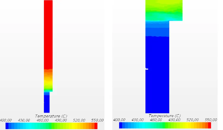
4.5.3 Temperature distribution
The axial sodium temperature linearly evolves from the cold pool temperature of 400°C to the hot pool temperature of 550°C (cf. Fig. 9). In contrast to the two separated regions obtained with the pressure distribution, the thermal flux smoothly diffuses throughout the sub-assembly, which leads to the absence of any thermal stratification. This regular evolution corresponds to a situation of a static fluid submitted to a temperature gradient between each side. Consequently, this thermal diffusion existence in the M-TT seems to be pushing the risk of an eventual thermal cracking of the hexagonal tube. However, it needs to be consolidated with CFD computations taking into account the sub-assemblies and the inter-assembly bypass.
Fig. 9 Temperature distribution on the total height of the M-TT (left) and zoom on the nozzle (right)
4.5.4 Comparison of analytical and numerical approaches
Table 1 shows the good agreement for the equilibrium injector flowrate, between CFD modelling and the analytical approach. The difference is less than 7.5%, which is not so much taking into account the rough 1D analytical model that includes some simplifications.
Table 1 Comparison between analytical and CFD equilibrium flowrates for different injector diameters and reduced pressure drops
Flowrate ∆𝑷𝒓 = 0.16 bar ∆𝑷𝒓 = 0.36 bar
injector Analytical CFD Analytical CFD
1 cm 2.6 kg/s 2.5 kg/s 3.91 kg/s 3.8 kg/s
2 cm 5.2 kg/s 5.2 kg/s 7.8 kg/s 7.6 kg/s
4 cm 10 kg/s 9.5 kg/s 15 kg/s 14 kg/s
The analysis of this table suggests that doubling the pressure variation only increases the injected flow by a factor of 1.5. In addition, this flowrate is directly proportional to the diameter of the injector.
These results are in agreement with the relation (9) established above, which is equivalent to: 𝑄𝑖𝑛𝑗= 𝐷𝑖𝑛𝑗∙ √𝜋4∙ 𝜌 ∙ 𝑆𝑜𝑢𝑡∙ ∆𝑃𝑟 with 𝐷𝑖𝑛𝑗 the injector diameter and ∆𝑃𝑟 the reduced pressure difference in the transfer tube. So, the flow increases as the square root of the pressure difference, while it evolves linearly with the injector diameter.
4.5.5 Sensitivity to the equilibrium injector flowrate The sensitivity to the injector flowrate (𝜕𝑄𝑟𝑒𝑠
𝜕𝑄𝑖𝑛𝑗 =
𝑆𝑜𝑢𝑡
𝑆𝑖𝑛𝑗 −
𝑄𝑟𝑒𝑠
𝑄𝑖𝑛𝑗) around the equilibrium flowrate has been established above, cf. (13). Again, Table 2 shows the good agreement for the sensitivity to the injector flowrate between CFD modelling and the analytical approach.
Table 2 Sensitivity to the injector flowrate for different conditions
𝝏𝑸𝒓𝒆𝒔 𝝏𝑸𝒊𝒏𝒋
⁄ ∆𝑷
𝒓 = 0.16 bar ∆𝑷𝒓 = 0.36 bar
injector Analytical CFD Analytical CFD
1cm 32 24 33.5 35
2cm 19 11.5 19 14
4cm 4 3 4.2 4
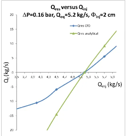
Fig. 10 represents the residual flowrate versus the injector flowrate near the equilibrium flowrate for both CFD and analytical approaches, in the case where the injector diameter is equal to 2 cm and the reduced pressure drop in the tube is 0.16 bar. The equilibrium injector flowrate is of 5.2 kg/s but the high value of the slope with an order of magnitude of 15 (19 with the analytical approach and 12 with the CFD one), makes the equilibrium quite sensitive to the injection flowrate.
Fig. 10 Sensitivity of the residual flowrate to the injector flowrate
The analytical approach has led to a simple formulation of the injector flowrate that allows a first dimensioning of the characteristics of the injector. These preliminary results have been refined by the CFD approach.
In the following part, we will consider the component scale that will be then integrated in the system scale.
5. Component scale: stand-alone 3D-modelling numerical approach
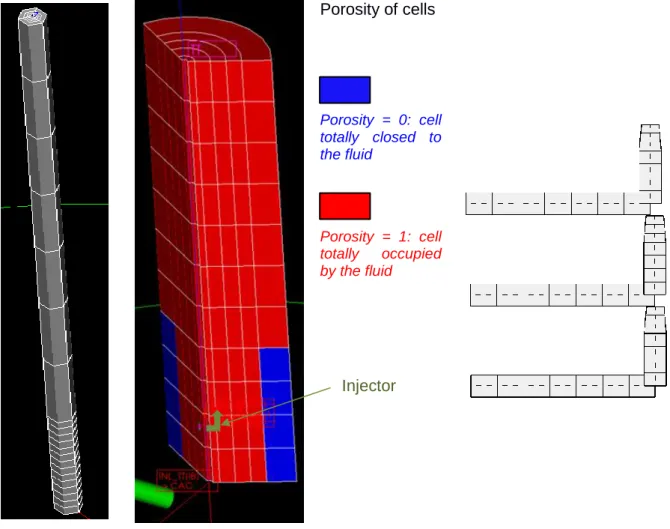
In this section, we present the stand-alone 3D-modelling of the M-TT at the component scale. As our goal is to include this component-scale model in a system-scale model of the SFR, we use the CATHARE code that allows this two-scale description. CATHARE is the French reference thermal-hydraulic system safety code [9] [10] originally devoted to the study of water-cooled reactor and extended to other designs including SFR [11]. It is used to model the compressible two-phase flow transients (normal-operation or accidental transients from any kind of failure or size and location of breaks) using a six-equation model (mass, momentum and energy) on a staggered space discretization. As a whole, the reactor system elements as pipes, primary pumps, intermediate heat exchangers and secondary circuits are generally modelled with 0D and 1D elements. However, it is possible to model components (core, steam generators …) with 3D elements. It is the case in this section where we use a 3D element to model the M-TT device. In particular, this approach is motivated by the fact that it is not possible to fully describe the presence of one-phase counter-current flows with 0D or 1D elements. The 3D mesh is constituted by 5x3x21 cells (radial x azimuthal x z-axis) with a cylindrical geometry; cf. Fig. 11 (left). The tube lower part (nozzle; Ø = 9 cm) and the upper part (Ø = 14 cm) are 0.85 m and 3.65 m in length, respectively. The eventual variations in volume are set using a porosity field. The porosity is null in the peripheral radial meshes of the nozzle part because the diameter is lower than in the upper part: ∅ 9 cm versus ∅14 cm, cf. Fig. 11 (center). Three injectors, modelled by 1D elements, cf. Fig. 11 (right), are connected to the M-TT 3D mesh. The equivalent diameter of the three injectors is 2 cm. Boundary conditions are prescribed at the injectors inlets (imposed mass flow or pressure) and at the top and bottom of the M-TT inlets (imposed pressures).
In an upscaling-like process based on the previous CFD results, we define global quantities to be conserved at the component scale, under a given reduced pressure difference between the hot and cold pools:
the bypass flowrate that would exist in the M-TT without injector,
the injected flowrate at equilibrium, meaning that there is no flowrate between the tube and the hot pool (negligible value in practise).
The singular head loss values in the 3D element and in the injectors are chosen in order to respect these CFD-prescribed global values. These head losses have been regularly applied all along the tube height. Moreover, the M-TT design envisaged for our typical SFR usually included the presence of an upper neutron shielding in the upper part of the tube. This has been taken into account by the use of a higher head loss value. Following this upscaling-like process, we approximatively recover the CFD value for the injected flowrate at equilibrium (𝑄𝑖𝑛𝑗 ~ 5 kg/s and 𝑄𝑟𝑒𝑠 ~ 0 kg/s) under the reduced pressure difference of 0.16 bar, cf. Fig. 12.
The rest of this section addresses simulations of the M-TT at the component scale in order to investigate the model answer to variations of the injector liquid flowrate and to the consequences of a two-phase injection (gas retention issue), as well as the cavitation risk.
Porosity of cells Porosity = 0: cell totally closed to the fluid Porosity = 1: cell totally occupied by the fluid
Fig. 11 Component scale: 3D meshing (left) – zoom on the porosity field at the junction between the nozzle and upper part (center) – 1D meshing of the 3 injectors (right)
5.1 Variations of the injector liquid flowrate
The analytical study (Section 3) and the CFD study (Section 4) give an insight in the non-equilibrium behavior of the M-TT under injector flowrate variations around the equilibrium injector flowrate value for a given reduced pressure difference between the pools. Our goal is to check the ability of the component-scale model to reproduce these phenomena. For this, we run computations under a reduced pressure difference of 0.16 bar and with various injector flowrate values and check the residual flowrate at the top of the M-TT, as explained in Section 4.5.5. Results are reported in Fig. 12. For an injector mass flowrate input, different residual mass flowrates are obtained depending on model details (3 distinct injectors or 1 equivalent injector). Given the component mesh resolution, we conclude to the trend of the residual flowrate estimated by the CATHARE model at the component scale is quite representative of the CFD one.
Fig. 12 Variations of the residual mass flowrate at the top of the M-TT versus the injector liquid flowrate
5.2 Risk of gas retention in the M-TT
Here, we face the issue of the reactor cover non-reactive gas (argon), trained in the primary circuit and injected in the M-TT by the injectors, as well as its behavior in the tube (trapped or released). The main risk should be the trapping of the gas in the M-TT and the neutron consequences on the neighbour assemblies (potential increase of the reactivity due to a void apparition).
In this study, a liquid sodium and argon gas mixture is considered with a mass concentration of the argon in the continuous gas phase of 0.999. We start from a steady state with an injector mass flowrate slightly greater than 5 kg/s. In this case, the flowrate is mainly directed toward the cold pool (4.25 kg/s) with a small flowrate toward the hot pool (0.75 kg/s) that is penalizing considering gas trapping. When the steady state is reached, the injector flow turns linearly in time into two-phase flow during 3 seconds. When the desired void fraction is reached, it is maintained during another 3 seconds, before suddenly stopping the gas injection. Two input void fractions α were used: one low void fraction value (α=10-2) and
one high void fraction value (α=0.6). These void fractions are typical of a low gas entrainment and of a bubble entrainment, respectively.
For the both cases, the gas quickly flows out the M-TT in typically one or two minutes. For the low gas entrainment case, the gas leaves the tube by the top and the bottom exits. While, in the bubble entrainment case, the gas mainly flows by the top exit, cf. Fig. 13. After this time delay, the M-TT recovers its initial inventory in liquid, cf. Fig. 14. Then, the issue of gas retention in the M-TT seems excluded.
Fig. 13 Gas injection in the M-TT: gas mass flowrate at the inlet and outlets – low void fraction case (left) – high void fraction case (right)
Fig. 14 Gas injection in the M-TT: gas volume in the M-TT – low void fraction case (left) – high void fraction case (right)
5.3 Risk of cavitation in the injector nozzle
In addition, this study gives an insight in the cavitation risk in the injector nozzle. The velocity increase at the nozzle induces a pressure decrease. But, even for the highest velocities (here, about 25 m/s), the pressure decrease does not lead to pressure levels lower than the saturation pressure at the temperature of the liquid sodium (about 105 Pa for the computed pressure, to compare to the saturation pressure of 50 Pa at 420°C).
Obviously, this result, depending on the nozzle geometry, would be to consolidate in the future.
Now, disposing of a M-TT component model, we face the integration of this one into a full system-scale model in the following of this paper.
6. System scale: system-code numerical approach
The objective of this part is to observe the impact of the M-TT implementation in the core of a typical SFR on the main thermal-hydraulic parameters, in normal operations and during an example of transient situation, using the same system-code than above.
6.1 Integration of the M-TT in the reactor modelling
The position of the M-TT in the reactor core is illustrated on Fig. 1. The reference thermal-hydraulic input deck of such a reactor is built with the CATHARE code, and represents the primary system with boundary conditions for the secondary circuit at the IHX. It is composed of 0D and 1D elements of the CATHARE code. Fig. 15 presents this CATHARE data deck, focusing on the central region of the vessel. The core sub-assemblies are grouped in derivations1: the inner derivations (fuel sub-assemblies, control rods, inter-assembly bypass …) are connected to a core downstream 0D element representing the central part of the hot pool entry area. The further derivations (in-vessel fuel storage and debugging, steel reflectors …) are connected to a 0D element representing the peripheral part of the hot pool entry area.
The M-TT model, composed of a 3D element as described in Section 5, has been integrated in the reactor input deck, as illustrated on Fig. 15. Compared to the previous section, the nozzle length is extended in order to reach the cold pool: the tube nozzle is 1.7 m height and the body is 3.65 m. The difference of total pressure ∆𝑃 between the two extremities of the tube is equal to 0.32 bar, corresponding to a reduced pressure ∆𝑃𝑟 (with gravity terms) of 0.135 bar. The head losses values have
been calibrated similarly to the Section 5, with respect to the new total length of the tube. There are 3 injectors per tube, which draw cold sodium from the diagrid. The upper extremity of the tube communicates with the hot pool, whereas the lower extremity communicates with the cold pool.
We associate a weight of 21 to the 3D element, in order to represent the 21 transfer tubes supposed to be present in the reactor core.
Fig. 15 M-TT connections with the volumes of the SFR input deck
The M-TT is at equilibrium (see Section 3.1) at nominal power, meaning that there is no flowrate going from the tube to the hot pool (negligible value in practise).
1
A derivation corresponds for CATHARE to a 1D element gathering several sub-assemblies, which have identical geometry, materials and neutronic properties.
Diagrid Hot pool
Cold pool
Central core outlet Peripheral core outlet
CORE
M-TT 3 injectors Primary pump6.2 Steady-state in normal operations
As previously explained, we want to investigate the thermal-hydraulic behavior of the primary system including the M-TT in normal operations. In this part, a computation simulating the SFR primary system with 21 TT is compared with a reference computation corresponding to the same system without M-TT. This is done for three steady-state power conditions: 100%, 80% and 60% of the Nominal Power (NP) cf. Table 3.
The CPU time corresponding to steady state computation for the whole model including the 21 M-TT is about 2.5 days on a standard desktop station (24 cores, 2 GHz and 32 Gb of RAM).
The primary flowrate going into the IHX is the sum of the flowrates going out of the top part of the core (red numbers in Table 3). This downstream core flow is divided in two parts (depending on the M-TT presence):
𝑄𝑝𝑟𝑖𝑚𝑎𝑟𝑦_𝐼𝐻𝑋 = 𝑄𝑐𝑜𝑟𝑒+ 𝑄𝑟𝑒𝑠 (15)
with 𝑄𝑐𝑜𝑟𝑒 = 𝑄𝑐𝑒𝑛𝑡𝑟𝑎𝑙_𝑐𝑜𝑟𝑒+ 𝑄𝑝𝑒𝑟𝑖𝑝ℎ𝑒𝑟𝑎𝑙_𝑐𝑜𝑟𝑒.
The modelling of the 21 M-TT slightly reduces the flowrate through the core. Indeed, at full power nominal conditions, the 21 M-TT bleed off a small portion of the primary flowrate entering in the diagrid (𝑄𝑖𝑛𝑗 ≈ 0.96% of the primary pumps flowrate 𝑄𝑝𝑟𝑖𝑚, see green cells related to M-TT in Table 3), which
does not go anymore in the core sub-assemblies. This flowrate reduction is balanced over all derivations.
The main part of the M-TT injector flowrate is discharged in the cold pool (𝑄𝑜𝑢𝑡 0.93% of 𝑄𝑝𝑟𝑖𝑚) and a small amount is discharged in the hot pool (𝑄𝑟𝑒𝑠 0.03% of 𝑄𝑝𝑟𝑖𝑚). Consequently, the flow feeding the primary IHX is slightly reduced (-0.93% of 𝑄𝑝𝑟𝑖𝑚). The tubes are close to equilibrium (cf. Section 3.1).
Table 3 Main thermal-hydraulic parameters for 100%, 80% and 60% NP steady state without / with M-TT
These insights at full power nominal conditions are also true for partial-power conditions: the equilibrium state of the transfer tubes is preserved, as shown on Table 3. The main tendencies related to the power reduction are:
- The flowrate ratio diverted by the transfer tubes (𝑄𝑖𝑛𝑗 0.96% of 𝑄𝑝𝑟𝑖𝑚) is independent of the power;
- The flowrate fraction of injected fluid going to the cold pool (𝑄𝑜𝑢𝑡/𝑄𝑖𝑛𝑗) slightly increases when
the power decreases.
Finally, as a whole, the main effect of the integration of transfer tubes with injectors in a SFR core at steady state (100%, 80% and 60% of NP) is the reduction of flowrate feeding the core sub-assemblies. This lack of flowrate for the core and IHX (primary side) does not exceed 1% of the reference core feeding flowrate, which is negligible.
Without M-TT With 21 M-TT Without M-TT With 21 M-TT Without M-TT With 21 M-TT
Qinj (%Qprim) 0,96% 0,96% 0,96%
Qout (%Qprim) 0,93% 0,94% 0,95%
Qcore_outlet (%Qprim) 92,94% 91,98% 92,94% 91,98% 92,94% 91,98%
Qres (%Qprim) 0% 0,03% 0% 0,02% 0% 0,01%
Qprim ary_IHX (%Qprim) 92,94% 92,01% 92,94% 92% 92,94% 91,99%
100% NP / Qprim = 8499 kg/s Power / Primary flowrate 80% NP / Qprim = 8133 kg/s 60% NP / Qprim = 7037 kg/s 0% 0% 0%
The tube functioning is therefore not affected by the steady state power level and remains at equilibrium, meaning that nearly no sodium is rejected into the hot pool by the M-TT. Moreover, no important reactor thermal-hydraulic perturbation is induced by adding transfer tubes in the core whatever the power is.
6.3 A loss of flow transient
The correct functioning at equilibrium state of the transfer tubes has been studied for fixed in time boundary conditions in the previous Section. At present, the objective of this part is essentially devoted to the characterization of M-TT behavior during a transient, with time dependent boundary conditions at both ends of the tube.
The studied transient is a Loss Of Flow (LOF): the primary pumps stop unintentionally and the flowrate in the primary circuit decreases until the establishment of a natural convection loop. The initial state corresponds to nominal conditions at 100% NP. We suppose that the IHX still operate with a nominal secondary flowrate, fostering the core heat removal. Consequently, the DHR exchanger is not activated. After a quick presentation of the main thermal-hydraulic features, we will stress on the differences of the transient simulations with and without M-TT.
6.3.1 Analysis of the main thermal-hydraulic parameters of the reactor during the transient
The simulation time lasts for 305 seconds, including 5 seconds of steady state at the beginning. Firstly, the pump rotation speed rapidly decreases jointly with the diagrid inflow (cf. Fig. 16), as well as the pressure in the diagrid (cf. Fig. 18). The primary flowrate decreases from a nominal value of 8500 kg/s to a stabilized value of 451 kg/s. It represents the natural convection flowrate.
As the cooling primary flowrate decreases, the core outlet sodium temperature increases from 550°C (nominal value) to 679°C in 20 sec. (cf. Fig. 17). It causes a core power drop by Doppler effect, which finally results in the core outlet temperature decrease once the control rods fall down (~ 19 sec.). After about 100 seconds, the reactor power and outlet core temperature continue to regularly decrease thanks to the IHX heat removal.
Fig. 16 Flowrates evolution in the diagrid and pump rotation speed evolution during a LOF transient without/with M-TT modelling
Due to the pump stop, by the law of communicating vessels, the hot pool level slightly decreases ( -0.2 m) and the cold pool level strongly increases ( +1.5 m) leading to the same level in the pools (∆ℎ
0 m). Simultaneously, the hot pool pressure remains nearly constant, whereas the cold pool pressure increases from 1.40 to 1.52 bar (cf. Fig. 18), which cancels the reduced overpressure ∆𝑃𝑟 between both
pools, cf. Equation (3).
Fig. 17 Power and inlet/outlet core temperature evolution during a LOF transient without/with M-TT modelling
6.3.2 Effects induced by the M-TT modelling
Globally the primary circuit behavior with and without M-TT is similar, as shown by Fig. 16 and Fig. 17. The pressure, temperatures and reactor power are not impacted by the M-TT introduction in the CATHARE data deck.
Let us discuss the M-TT behavior during the LOF transient, cf. Fig. 18. Starting from the steady state, where the transfer tubes bleed off 81.6 kg/s of sodium from the diagrid volume thanks to the injectors, mainly transferred to the cold pool (79.3 kg/s), the sodium pumped by the injectors decreases towards zero with the primary flowrate and the diagrid pressure.
At the very beginning of the transient, during a short time period (from 5.5 to 17.3 sec.), the momentum injected by the injectors is no more sufficient to counter-balance the pressure difference between the two pools. At that moment, a reverse flow takes place at the top of the tubes: the sodium flows down the M-TT. Shortly after, the cold pool pressure increases until the cancellation of the reduced overpressure between the hot and cold pools that exists at steady state. It induces in the tubes
at the upper extremity, another flow direction change around 18 seconds: the sodium again goes out of the M-TT into the hot pool with a stronger flowrate than the residual one at steady state, at the lower extremity, a reversal of the initial downward flow after 35 seconds.
Finally after 170 sec., a new stabilized state is established: the 21 M-TT are fed with sodium by the cold pool (23.6 kg/s) and discharge the flow mainly to the hot pool (21.8 kg/s) and in a small amount to the diagrid (1.8 kg/s), through the injectors.
Therefore, during this particular LOF transient computed with CATHARE, the 21 M-TT of the core behave on the long term (after 200 sec. of transient) like a core bypass and transfer the sodium from the cold to the hot pool. The bypass flowrate through the 21 M-TT represents less than 6% of the natural circulation loop total flowrate entering through the core admission ( 450 kg/s). It can be noted that this bypass has a very low impact on the reactor transient.
7. Conclusion and prospects
In the context of the integrated Sodium-cooled Fast Reactor, we have presented an innovative version of the safety complementary device M-TT to prevent or mitigate the consequences of a hypothetical severe accident. It provides a passage to the core catcher for a hypothetical corium coming from molten fuel sub-assemblies (mitigation). But, in addition, it induces an improvement of the decay heat removal capacity by natural convection between the core and active hot-pool DHR in case of loss of primary flow and of unavailable IHX (prevention). This device is set by empty transfer tubes, in place of some fuel sub-assemblies present in the reactor core, using the innovative passive device PHYLOCK, based on the concept of hydraulic diode. One or more injectors fed by the primary pumps, ensure the tightness between the hot and cold pools in normal operations. But, in case of loss of the primary pumps, it provides a direct flow path between the hot pool, equipped with DHR exchangers, and the cold one leading to an easier passage of cold sodium towards the cold pool.
This paper has focused on the assessment of the lock function and of the slight impact induced by our device on the thermal-hydraulic behavior of the reactor during normal operations. Up-scaling investigations were done through the local scale to the system scale. At the local scale, we have developed an analytical analysis confirmed by CFD numerical simulations. A 3D model, developed at the component scale with a thermal-hydraulic system code and based on the up-scaling of the CDF results, has allowed us to investigate the eventual gas retention and the cavitation issues in the M-TT. Finally, this component model has been integrated in a full reactor model simulation at the system scale. Thanks to these computations, we claim that the lock function is kept during the normal-operation steady states at various power regimes (here, 100%, 80% and 60% of the nominal power). The residual leak flowrate represents no more than 1% of the primary pump flow. In addition, we conclude that no important modification of the reactor thermal-hydraulic is brought by adding transfer tubes in the core. It is also true for a typical full-power loss of forced flow transient leading to a natural convection cooling. In this case, the transfer tubes act as extra bypasses leading to lower the fraction of the natural-convection flow (about -6%) passing through the core with only slight modifications of the core temperature.
Moreover, exploratory 3D-component computations show no gas retention in the device: bubbles from an argon-polluted sodium flowing through the M-TT are quickly ejected into cold and hot pools in a few minutes, whatever the void fraction is (here, 10-2 or 0.6). Moreover, the saturation pressure for the local sodium temperature, that is a necessary condition for cavitation issues, is never reached at the injector nozzle.
As perspectives, we envisage on one hand, to consolidate these results by other studies concerning normal operations and design basis accident transients. Also, we plan to study the severe-accident prevention capacity of the M-TT through natural-convection simulations including a DHR exchanger model at the system scale coupled with a CFD hot pool model at the local scale. On the other hand, experimental assessment of the M-TT thermal-hydraulics and its sensibility to reactor parameters should be carried out to validate the present numerical modelling.
8. Glossary
Abbreviation/variable Definition
0D, 1D, 3D Geometry in zero dimension, one dimension, three dimensions CFD Computational Fluid Dynamics
DHR Decay Heat Removal
IHX Intermediate Heat eXchanger
LOF Loss Of Flow
M-TT Complementary safety device devoted to Mitigation (Transfer Tube)
NP Nominal Power
PHYLOCK Passive HYdraulic LOCK
RANS Reynolds Averaged Navier-Stokes
RPM Revolutions Per Minute
SFR Sodium-cooled Fast Reactor
ε Turbulent kinetic energy dissipation rate (J/kg/s) 𝜙𝑖𝑛𝑗 Injector diameter (m)
𝜌 Average sodium density (kg/m3) g Gravity acceleration (m/s2)
𝐻 Height of the flow reversal region (m) 𝐻𝑜𝑢𝑡 Height below the flow reversal region (m)
𝐻𝑡 Height above the flow reversal region (m) 𝐻𝑇𝑇 Total height of the transfer tube (m)
∆ℎ Difference of free levels between the hot and the cold pools (m) k Turbulent kinetic energy (J/kg)
𝑃𝑖𝑛𝑗 Pressure at the injector nozzle (Pa)
𝑃𝑐 Pressure at the lower part of transfer tube (Pa)
𝑃ℎ Pressure at the upper part of transfer tube (Pa) ∆𝑃 = 𝑃ℎ− 𝑃𝑐 Pressure drop in the transfer tube (Pa)
𝑄𝑐𝑜𝑟𝑒 Core flowrate (kg/s)
𝑄𝑝𝑒𝑟𝑖𝑝ℎ𝑒𝑟𝑎𝑙_𝑐𝑜𝑟𝑒 Flowrate in the peripheral part of the core (kg/s) 𝑄𝑐𝑒𝑛𝑡𝑟𝑎𝑙_𝑐𝑜𝑟𝑒 Flowrate in the central part of the core (kg/s)
𝑄𝑝𝑟𝑖𝑚 Flowrate delivered by the primary pumps (kg/s) 𝑄𝑝𝑟𝑖𝑚𝑎𝑟𝑦_𝐼𝐻𝑋 Primary flowrate going into the IHX (kg/s)
𝑄𝑖𝑛𝑗 Injector flowrate (kg/s)
𝑄𝑖𝑛𝑗0 Injector flowrate at equilibrium (kg/s)
𝑄𝑜𝑢𝑡 Flowrate at the bottom outlet of the transfer tube (kg/s)
𝑄𝑟𝑒𝑠 Residual flowrate at the top outlet of the transfer tube (kg/s) 𝑆𝑖𝑛𝑗 Injection nozzle section (m2)
𝑆𝑜𝑢𝑡 Cross-section of the transfer tube (m2) 𝑣𝑖𝑛𝑗 Injection velocity (m/s)
𝑣𝑜𝑢𝑡 Sodium velocity in the lower part of the transfer tube (m/s)
9. References
[1] Some thermal-hydraulic challenges in sodium cooled fast reactors. D. Tenchine. Nuclear Engineering and Design, 240:1195–1217, 2010
[2] Fuel discharge toward the core catcher under severe accident conditions with mitigation devices. A. Bachrata, N. Marie, F. Bertrand, A. Edeline, R. Kubota, K. Kamiyama and S. Kubo. Submitted to International Congress on Advances in Nuclear Power Plants (ICAPP '19), Juan-les-Pins, France, May 12-15, 2019
[3] Status of severe accident studies at the end of the conceptual design of ASTRID: Feedback on mitigation features. F. Bertrand, N. Marie, A. Bachrata, V. Brun-Magaud, J.B. Droin, X. Manchon, K. Herbreteau, B. Farges, B. Carluec, S. Poumerouly and D. Lemasson. Nuclear Engineering and Design 326: 55-64, 2018
[4] Integral fast reactor comprising a device for the passive locking of the hydraulic path. G.-M. Gautier and M. Belliard. Patents n° PCT/FR2017/051797, 2017
[5] Fluid Mechanics. S. Candel, Dunod 1995
[6] CD Adapco, STAR-CCM+ User Guide Version 13.04. http://www.cd-adapco.com
[7] A quantitative CFD benchmark for Sodium Fast Reactor fuel assembly modeling. E. Baglietto et al. Massachusetts Institute of Technology, United States, Annals of Nuclear Energy, 64:32-42, 2014
[8] Physical properties of sodium: a contribution to the estimation of critical coordinates. P. Petiot and J.M Seiler. High Temperature and High Pressure, 16:289-293, 1984
[9] The CATHARE code strategy and assessment. F. Barré and M. Bernard. Nuclear Engineering and Design, 124(3):257-284, 1990
[10] CATHARE 3: a new system code for thermal-hydraulics in the context of the NEPTUNE project. Ph. Emonot, A. Souyri, J.-L. Gandrille and F. Barré. 13th International Topical Meeting on Nuclear Reactor Thermal Hydraulics (NURETH-13), Kanazawa City, Ishikawa Prefecture, Japan, IAEA INIS 43(04), September 27 - October 2, 2009
[11] Status of CATHARE code for sodium cooled fast reactors. D. Tenchine, R. Baviere, P. Bazin, F. Ducros, G. Geffraye, D. Kadri, F. Perdu, D. Pialla, B. Rameau and N. Tauveron. Nuclear Engineering and Design, 245:140-152, 2012