RESEARCH OUTPUTS / RÉSULTATS DE RECHERCHE
Author(s) - Auteur(s) :
Publication date - Date de publication :
Permanent link - Permalien :
Rights / License - Licence de droit d’auteur :
Bibliothèque Universitaire Moretus Plantin
Institutional Repository - Research Portal
Dépôt Institutionnel - Portail de la Recherche
researchportal.unamur.be
University of Namur
Strategy for Database Application Evolution: The DB-MAIN Approach
Hick, Jean-Marc; Hainaut, Jean-Luc
Published in:
Proc. of the 22nd Int. Conf. on Conceptual modeling (ER'03)
Publication date: 2003
Link to publication
Citation for pulished version (HARVARD):
Hick, J-M & Hainaut, J-L 2003, Strategy for Database Application Evolution: The DB-MAIN Approach. in IY Song, W Stephen, L Tok, W Ling & P Scheuermann (eds), Proc. of the 22nd Int. Conf. on Conceptual modeling (ER'03): 22nd International Conference on Conceptual Modeling. Springer, Berlin, pp. 291-306.
General rights
Copyright and moral rights for the publications made accessible in the public portal are retained by the authors and/or other copyright owners and it is a condition of accessing publications that users recognise and abide by the legal requirements associated with these rights.
• Users may download and print one copy of any publication from the public portal for the purpose of private study or research. • You may not further distribute the material or use it for any profit-making activity or commercial gain
• You may freely distribute the URL identifying the publication in the public portal ?
Take down policy
If you believe that this document breaches copyright please contact us providing details, and we will remove access to the work immediately and investigate your claim.
Strategy for Database Application Evolution:
the DB-MAIN Approach
Jean-Marc Hick, Jean-Luc Hainaut
University of Namur, Computer Sciences Department Rue Grandgagnage 21, B-5000 Namur, Belgium {jmh, jlh}@info.fundp.ac.be, http://www.info.fundp.ac.be/libd
Abstract. While recent data management technologies, e.g., object-oriented, address the problem of databases schema evolution, standard information sys-tems currently in use raise challenging problems when evolution is concerned. This paper studies database evolution from the developer point of view. It shows how requirements changes are propagated to the database schemas, to the data and to the programs through a general strategy. This strategy requires the docu-mentation of the database design. When absent, this docudocu-mentation has to be re-built through reverse engineering techniques. The approach relies on a generic database model and on the transformational paradigm that states that database en-gineering processes can be modelled by schema transformations. Indeed, a trans-formation provides both structural and instance mappings that formally define how to modify database structures and contents. The paper then analyses the pro-blem of program modification and describes a CASE tool that can assist develo-pers in their task of system evolution.
1
Introduction
A database application is a software system that includes complex and high-volume per-sistent data stored in a set of files or in a genuine database. Such an application must evol-ve due to environment requirements changes.
The lack of support (methods and tools) in the database maintenance and evolution do-main is now recognized. Systematic rules for translation of requirement modifications into technical modifications of the application are still unknown particularly when tracea-bility of design and maintenance processes is missing. Current CASE1 tools automatical-ly generate incomplete DDL2 code that must be modified to be truly operational. If data-base specifications change, these tools produce new code which is disconnected from the updated version. In addition, data conversion and program modification are up to the pro-grammer.
Quite frustratingly, though schema evolution has been widely studied in the scientific literature, yielding interesting results, the latter still has to be implemented into practical technology and methodology. The problem of database evolution has first been studied for standard data structures. Direct relational schema modification has been analysed by [2], [17] and [18], among others. The propagation of conceptual modifications on relatio-nal schemas are arelatio-nalysed in [17] and [20]. The object paradigm is a good framework to develop elegant solutions through the concepts of schema and instance versioning ([1], [4], [16]).
1 Computer Aided Software Engineering. 2 Data Definition Language.
Several research projects have addressed the problem of change in information sys-tems. For example, the NATURE project [14] has developed a requirement engineering framework playing an important role in modification management. The SEI-CMU pro-ject studied the evaluation of the evolution capacity of existing information systems [5]. Closer to our data-centric approach, the Varlet project [13] adopts a reverse engineering process that consists in two phases. In the first one, the different parts of the original da-tabase are analysed to obtain a logical schema for the implemented physical schema. In the second phase, this logical schema is transformed into a conceptual one that is the basis for modification activities.
This paper analyses the phenomenon of data evolution in database applications as the modification of three system components, namely the data structures, the data and the programs, as an answer to requirement changes at different levels of abstraction. After the problem statement (section 2), the paper introduces the methodological foundations (sec-tion 3). Finally, sec(sec-tion 4 describes the evolu(sec-tion strategy of the DB-MAIN approach3 and section 5 closes the paper.
2
Problem Statement
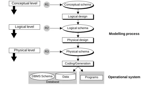
The phenomenon of evolution is analysed in the framework of classical modelling ap-proaches, that are now familiar to database developers. These approaches consider the da-tabase design as a complex activity made up of elementary processes based on three abs-traction levels, each of them dealing with homogeneous design requirements, i.e., the conceptual, logical and physical levels. One generally consider three kinds of require-ments, namely functional (to meet the user requirements in terms of system functions), organizational (to answer the framework changes in a company) and technical (adapta-tion to the new technical or hardware constraints). In Fig. 1, the conceptual schema meets the organizational and functional requirements R1, while the logical schema satisfies the DBMS4-dependent technical requirements R2 and the physical schema integrates the physical requirements R3. The operational system contains the database (structures and data) and the programs. According to the most commonly agreed approaches, the concep-tual schema is translated into a DBMS model-dependent logical schema, which is in turn enriched into the physical schema. These translation processes are basically of transfor-mational nature.
We adopt the hypothesis that all the application specifications for each abstraction le-vel and the trace of their design processes, i.e., the transformations, are available. This assumption is of course unrealistic in many situations, in which the program source code and DDL scripts (or DBMS data dictionary contents) are often the only available docu-mentation. In this context, the strategies we are going to develop must be completed to take the lack of high-level specifications into account.
The database application evolution translates changes in the requirements into system changes. This paper focuses on the persistent data, i.e., the set of files or databases that store information on the application domain. More precisely, the problem can be
summa-3 DB-MAIN stands for Database Maintenance and Evolution. This approach has been grossly
described in [7] and has been developed in detail in [12].
rised as following: how must a change in a schema be propagated to (1) the lower level schemas, including the DDL code, (2) the data and (3) the application programs.
This study relies on a non-temporal approach, according to which all the application components (i.e., the schemas, the data and the programs) are replaced by new versions. In particular, the data are transformed in such a way that they become unavailable in their previous form. The application programs can use the new data only after being transfor-med accordingly. This strategy applies on both legacy and modern database applications and contrasts with advanced systems where the modification of the database schema is translated into the addition of a new version. In such schema/data versioning approaches ([15],[17]), the old schema is preserved and the access to its data is stored or calculated. For example, removing a property from a conceptual class is ultimately translated in our approach into the removal of the corresponding column through the query: alter table <table_name> drop <column_name>.
Fig. 1. Standard modelling approach divided into three abstraction levels.
3
Methodological Foundations
Requirement modification is translated into specification changes at the corresponding level (we ignore the translation rules in this paper). To ensure specification consistency, these changes must be propagated upwards and downward to other abstraction levels. Due to the complexity of the process, it must be supported by a CASE tool, which must meet three conditions.
• Genericity: the environment must offer a generic model of specification representation whatever the abstraction level, the technology or the paradigm on which the applica-tion relies.
• Formality: it must describe formally the database engineering activities.
• Traceability: the links between specifications must be rigorously recorded. They must be analysed to provide the information necessary for the modification propagation.
Logical design R1 Conceptual level Modelling process DBMS Schema Database
Programs Operational system Conceptual schema Data Physical design Logical schema Coding/Generation Physical schema R2 R3 Logical level Physical level
The DB-MAIN approach to database evolution is based on three concepts that imple-ment these requireimple-ments: generic representation model (section 3.1), transformational ap-proach (section 3.2) and history management (section 3.3).
3.1 Generic Model of Specification Representation
The DB-MAIN model has generic characteristics according to two dimensions:
• specification representation at each abstraction level: conceptual, logical and physical; • coverage of the main modelling paradigms or technologies such as ERA, UML, ORM,
objects, relational, CODASYL, IMS, standard files or XML models.
It is based on the Generic Entity/Relationship model and supports all the operational models through a specialization mechanism. Each model is defined as a sub-model of the generic model. A sub-model is obtained by restriction, i.e., by selecting the relevant jects, by defining the legal assemblies through structural predicates, by renaming the ob-ject according to the model taxonomy and by choosing a suitable graphical representa-tion. Fig. 2 presents schemas according to classical sub-models for the three abstraction levels: ERA (Merise style), relational and Oracle 8.
Fig. 2. Graphical views of conceptual, logical and physical schemas.
In Fig. 2a, PERSON, CUSTOMER, SUPPLIER, ORDER and ITEM are entity types or object classes (ET). CUSTOMER and SUPPLIER are subtypes of PERSON (supertype). Totality and disjunction constraints (P = partition) are defined on these subtypes. Attri-butes NumPers, Name, Address and Telephone characterize PERSON (as well as
CUS-TOMER and SUPPLIER). Address is a compound attribute while Telephone is
multiva-lued. Attributes Number, Street and City are components of Address. Number is optional.
place, reference and offer are binary relationship types (RT). reference has an attribute. ORDER plays two roles in place and reference. Each role has minimal and maximal
car-a) Conceptual schema b) Relational logical schema c) Relational (Oracle 8) physical schema
0-N 0-N reference Quantity 0-N 1-1 place 0-N 1-1 offer P SUPPLIER NumSup NumVAT id: NumSup PERSON NumPers Name Address Number[0-1] Street City Telephone[0-5] id: NumPers ORDER NumOrder Date id: NumOrder ITEM NumItem Description Price id: NumItem CUSTOMER NumCus Account id: NumCus TELEPHONE NumPers Telephone id: NumPers Telephone ref: NumPers SUPPLIER NumSup NumVAT id: NumSup REFERENCE NumItem NumOrder Quantity id: NumOrder NumItem ref: NumOrder ref: NumItem PERSON NumPers NumCus[0-1] NumSup[0-1] Name Add_Number[0-1] Add_Street Add_City id: NumPers id': NumCus equ id': NumSup equ exact-1: NumCus NumSup ORDER NumOrder Date NumCus id: NumOrder ref: NumCus ITEM NumItem Description Price NumSup id: NumItem ref: NumSup CUSTOMER NumCus Account id: NumCus TELEPHONE NUMPERS TELEPHONE id: NUMPERS TELEPHONE acc ref: NUMPERS SUPPLIER NUMSUP NUMVAT id: NUMSUP acc REFERENCE NUMITEM NUMORDER QUANTITY id: NUMORDER NUMITEM acc ref: NUMORDER ref: NUMITEM acc PERSON NUMPERS NUMCUS[0-1] NUMSUP[0-1] NAME ADD_NUMBER[0-1] ADD_STREET ADD_CITY id: NUMPERS acc id': NUMCUS equ acc id': NUMSUP equ acc exact-1: NUMCUS NUMSUP ORDER NUMORDER DATEORD NUMCUS id: NUMORDER acc ref: NUMCUS acc ITEM NUMITEM DESCRIPTION PRICE NUMSUP id: NUMITEM acc ref: NUMSUP acc CUSTOMER NUMCUS ACCOUNT id: NUMCUS acc SPC_CUS TELEPHONE CUSTOMER ORDER REFERENCE PERSON SPC_SUP ITEM SUPPLIER
dinalities (N stands for infinity). reference is called a many-to-many relationship type and
place an one-to-many relationship type. CUSTOMER is identified by NumCus.
Fig. 2b depicts a relational schema in which PERSON, CUSTOMER, SUPPLIER,
TE-LEPHONE, ORDER, ... are tables. NumPers, NumCus and Name are columns of PER-SON. Name is mandatory and Adr_Number is optional (nullable). PERSON has a primary
identifier (primary key) NumPers and two secondary identifiers NumCus and NumSup.
ORDER.NumCus, as well as PERSON.NumCus, are foreign keys (ref or equ) targeting CUSTOMER. All the values of CUSTOMER.NumCus also appear as non-null values of PERSON.NumCus. This inclusion constraint forms with the foreign key an equality
cons-traint (equ). PERSON is submitted to an exactly-one conscons-traint (exact-1), i.e., for each row of this table, only one column among NumSup and NumCus has a non-null value.
In Fig. 2c, the names of tables and columns are compliant with the SQL syntax and includes physical, performance-oriented constructs. For example, Date (reserved word) becomes DATEORD in ORDER. Indexes (access keys) are defined on columns such as
NUMPERS of PERSON and NUMSUP of ITEM. Storage spaces (called TABLESPACE
in Oracle) are defined: SPC_SUP contains the rows of tables ITEM and SUPPLIER.
3.2 Transformational Approach
Database engineering processes can be defined as a sequence of data structure
transfor-mations [3]. Adding an entity type, renaming an attribute, translating a relationship type
into a foreign key are elementary transformations. They can be combined to build more complex processes such as schema normalization, logical schema optimization or DDL code generation. The concept of transformation used in this paper is formally described in [8], but we will briefly present some of its principles.
A transformation consists in deriving a target schema S' from a source schema S by replacing construct C (possibly empty) in S with a new construct C' (possibly empty). More formally, a transformation Σ is defined as a couple of mappings <T,t> such as: C' = T(C) and c' = t(c), where c is any instance of C and c’ the corresponding instance of C’. Structural mapping T explains how to modify the schema while instance mapping t states how to compute the instance set of C' from the instances of C (Fig. 3). Structural mapping T is a couple of predicates <P,Q> where P are the minimal preconditions C must satisfy and Q the maximal postconditions observed in C’. We obtain: Σ = <P,Q,t>. P (resp. Q) are second order predicates that define the properties of structure C (resp. C’).
Fig. 3. General transformation pattern.
Any transformation Σ can be given an inverse transformation Σ’ = <T’,t’> such as T’(T(C))=C. If, in addition, we also are provided with instance mapping t’ such as: t’(t(c))=c, then Σ (and Σ’) are said semantics-preserving or reversible. If <T',t'> is also reversible, Σ and Σ’ are called symmetrically reversible.
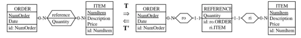
Fig. 4 graphically illustrates the structural mapping T of the transformation of a rela-tionship type into an entity type. This classical transformation appears in logical design,
C c C’ = T(C) c’ = t(c) instance-of instance-of T t
where complex structures, such as n-ary or many-to-many relationship types must be re-placed with simple, flat structures. In this example, the relationship type reference is transformed into the entity type REFERENCE and the one-to-many relationship types ro and ri. The precondition of this transformation is void (all RT can be transformed). The postcondition states the properties of the resulting entity type, relationship types and constraints. The instance mapping explains how each REFERENCE entity derives from a reference relationship. The inverse transformation, denoted T’ in Fig. 4, transforms the entity type REFERENCE into the relationship type reference. A complete formal descrip-tion of this transformadescrip-tion can be found in [8].
Fig. 4. The relationship type reference is transformed into an entity type REFERENCE. A transformation is entirely specified by its signature, which gives the name of the transformation, the name of the objects concerned in the source schema and the name of the new objects in the target schema. For example, the signatures of the transformations represented in Fig. 4 are:
T: (REFERENCE,{ro,ri}) ← RT-to-ET(reference) T’: reference ← ET-to-RT(REFERENCE)
The first expression reads as following: by application of the RT-to-ET transformation on the relationship type reference, a new entity type REFERENCE and two new rela-tionship types ri and ro are created. Note that all objects must not be mentioned in a si-gnature. Such is the case of relationship types ri and ro to which REFERENCE participa-tes.
The notion of semantics of a schema has no generally agreed upon definition. We as-sume that the semantics of S1 include the semantics of S2 iff the application domain
des-cribed by S2 is a part of the domain represented by S1. Though intuitive and informal,
this definition is sufficient for this presentation. In this context, three transformation ca-tegories can be distinguished:
• T+ collects the transformations that augment the semantics of the schema (for example adding an entity type).
• T- includes the transformations that decrease the semantics of the schema (for example adding an identifier).
• T= is the category of transformations that preserve the semantics of the schema (for example the transformation of a relationship type into an entity type).
Transformations in T= are mainly used in logical and physical schema production, while T+ and T- transformations make up the basis of specification evolution process.
3.3 History
For the sake of consistency, we consider that the requirement modifications applied at a given abstraction level must be propagated at the other levels. For example, adding a co-lumn to a table must imply the addition of the corresponding attribute to the entity type implemented by this table. Conversely, removing a one-to-many relationship type must be followed by the removal of the corresponding foreign key in the logical and physical
1-1 0-N ro 1-1 ri 0-N 0-N 0-N reference Quantity REFERENCE Quantity id: ro.ORDER ri.ITEM ORDER NumOrder Date id: NumOrder ORDER NumOrder Date id: NumOrder ITEM NumItem Description Price id: NumItem ITEM NumItem Description Price id: NumItem T ⇒ ⇐ T'
schemas. As far as evolution is concerned, keeping track of the design transformations is a necessity, as we will see, to avoid manually the reformulation of the design transforma-tion sequence for each evolutransforma-tion modificatransforma-tion [7].
The trace of the transformations that produce the schema Sj from schema Si is called the history of the transformation process, and is noted Hij. The composition of a sequence of elementary transformations Hij is also a (macro-)transformation, so that we can use the functional notation: Sj = Hij(Si) with Hij = Tn°...°T2°T1, that will be noted <T1 T2 ... Tn> in the following.
Using the signature notation, the following history, named LD0, describes how the conceptual schema of Fig. 2a has been transformed into the relational schema of Fig. 2b.
LD0 = < T1:(pers_cus,pers_sup) ← ISA-to-RT(PERSON,{CUSTOMER,SUPPLIER}) T2:(REFERENCE,{ord_ref,ite_ref}) ← RT-to-ET(reference) T3:(TELEPHONE,have) ← Att-to-ET-inst(PERSON.Telephone) T4:(Add_Number,Add_Street,Add_City) ← disaggregate(PERSON.Address) T5:(PERSON.NumCus) ← RT-to-FK(pers_cus) T6:(PERSON.NumSup) ← RT-to-FK(pers_sup) T7:(TELEPHONE.NumPers) ← RT-to-FK(have) T8:(ORDER.NumCus) ← RT-to-FK(place) T9:(ITEM.NumSup) ← RT-to-FK(offer) T10:(REFERENCE.NumOrder) ← RT-to-FK(ord_ref) T11:(REFERENCE.NumItem) ← RT-to-FK(ite_ref) >
When the transformations recorded in Hij are applied to Si, Hij is said to be replayed on Si. A history can be manipulated if several rules are respected (see [9] for more de-tails):
• Exhaustivity: the transformations are recorded precisely and completely to allow the inversion of non semantics-preserving transformations (reversing a delete transforma-tion requires a descriptransforma-tion of all aspects of the deleted objects).
• Normalization: the history is monotonous (no rollback) and linear (no multiple branch).
• Non-competition: a history is attached to one schema and only one user can modify it.
4
Evolution Strategy
Our approach has been developed for evolution of relational database applications, but other models can be coped with minimal efforts thanks to the genericity of the model and of the transformational approach. This choice allows us to build a modification typology and to design concrete conversion tools that can be used with systems developed in a third-generation language such as COBOL/SQL or C/SQL.
To make database applications evolve, the design history must be available. In parti-cular, the three levels of specification must exist and are documented, together with the histories of the inter-level transformation processes. In other words, the database is fully documented through its conceptual, logical and physical schemas and the histories of the conceptual-to-logical and logical-to-physical processes. In most cases, this hypothesis is not met: some (or all) levels are missing, incomplete or obsolete. Sometimes, only the source code of the programs and of the data structures are available. In these cases, the documentation and the histories must be rebuilt thanks to reverse engineering techniques that are not addressed in this paper. The reverse engineering approach we have defined is
described in [6] and [10] while the process of rebuilding histories has been developed in [9].
4.1 Evolution Scenarios
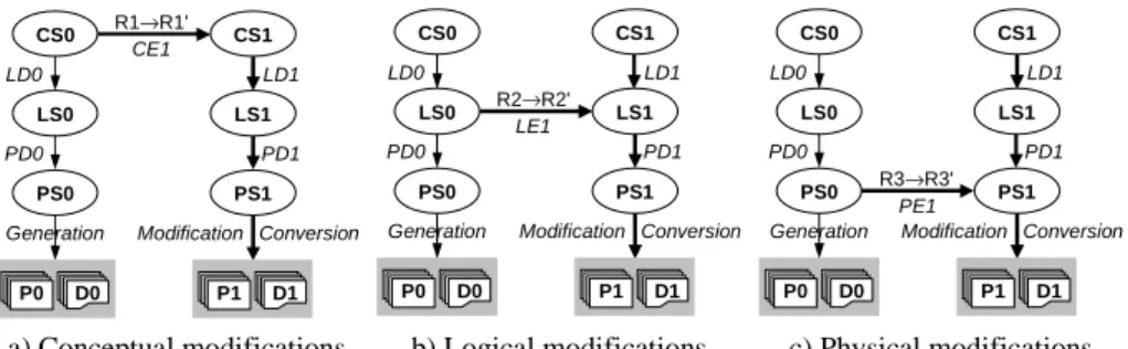
Three scenarios, one for each abstraction level, have been defined (Fig. 5). The initial spe-cifications are available as the three standard schemas: conceptual (CS0), logical (LS0) and physical (PS0) schema. The operational components are the database (D0: data and structures) and the programs (P0). LD0 (resp. PD0) are the histories that describe the transformations applied to CS0 (resp. LS0) to obtain LS0 (resp. PS0). The scenarios are constrained by the following hypothesis: the change must be applied on the relevant level. For instance, adding a new property to an application class must be translated into the ad-dition of an attribute to a conceptual entity type, in CS0, and not by adding a column to a table in LS0.
Fig. 5. Propagation of modifications at each abstraction level.
In the first scenario (Fig. 5a), the modifications translate changes in the functional re-quirement into conceptual schema updates. This new state is called CS1. The problem is the propagation of modifications towards the logical, physical and operational layers, lea-ding to the new components LS1, PS1, P1 and D1, and to the revised histories LS1 and PS1. The second scenario (Fig. 5b) addresses logical schema modifications. Though the conceptual schema is kept unchanged (CS1 = CS0), the logical design history LD0 must be updated as LD1 and the modifications must be propagated in the physical and opera-tional layers. In the third scenario (Fig. 5c), the designer modifies the physical schema to meet, e.g., new performance requirements. The physical design history is updated and the operational layer is converted.
The evolution strategy comprises four steps: database schema modification (section 4.2), schema modification propagation (section 4.3), database conversion (section 4.4) and program modification (section 4.5).
4.2 Database Schema Modification
In Fig. 5a, the requirements met by CS0 evolve from R1 to R1'. The analyst copies the schema CS0 into CS1 and translates the changes into modifications of CS1. The transfor-mations applied to CS0 to obtain CS1 are recorded into history CE1, so that CS1 = CE1(CS0). In Fig. 5b, the schema LS0 is modified to obtain LS1. The logical evolution transformations are recorded in the history LE1. Note that the designer can also modify the logical schema by using other transformations than those used in LD0, without
modi-a) Conceptual modifications. b) Logical modifications. c) Physical modifications. R1→R1' CS0 CS1 LD0 LD1 CE1 LS0 LS1 PD0 PD1
Generation Conversion Modification
P0 D0 P1 D1 PS0 PS1 CS0 CS1 LD0 LD1 LS0 LS1 PD0 PD1
Generation Conversion Modification
P0 D0 P1 D1 PS0 PS1 R2→R2' LE1 CS0 CS1 LD0 LD1 LS0 LS1 PD0 PD1
Generation Conversion Modification
P0 D0 P1 D1 PS0 R3→R3' PS1
fying the conceptual objects. For example, a multivalued attribute transformed into a se-ries of single-valued columns will now be transformed into an autonomous table. In this case, though the conceptual schema does not change, the first scenario is used. CE1 is empty and CS1 is equivalent to CS0, but the logical design history LD1 contains the new transformation (cf. section 4.3). In Fig. 5c, the physical schema PS0 is transformed into PS1 and the modification transformations are recorded in PE1.
Our approach is based on a set of standard schema modifications that accounts for most evolution needs. A detailed study of modification typology in conceptual, logical and physical levels is proposed in [12] and [17].
Thereafter, we are considering the first scenario for the following change: the
cardi-nality of the multivalued attribute Telephone becomes [0-2] in the conceptual schema of Fig. 2a. This example will be analysed for each step of the evolution strategy process. The
conceptual evolution history CE1 contains one signature: change-max-card(PER-SON.Telephone,2).
4.3 Schema Modification Propagation
At this level, all the specifications and the histories must be updated according to the mo-difications described in section 4.2.
In the first scenario, the new conceptual schema CS1 is transformed into a logical schema LS1 that is as close as possible to the former version LS0 and that integrates the conceptual modifications. The LD0 history is replayed on a copy of CS1 renamed LS1. This history contains the necessary operations to transform a conceptual schema into a relational logical one (for example Fig. 2b). The relational transformations belong essen-tially to the T= category.
When the LD0 history is replayed on the new conceptual schema CS1, four situations are possible according to the type of modification:
1. Unchanged object: the transformations of LD0 concerning this object are executed wi-thout modification.
2. Created object: the transformations of LD0 have no effect. The designer must specifi-cally process the new object.
3. Removed object: the transformations of LD0 concerning this object can be applied but they have no effect.
4. Modified object: for minor modifications, the transformations concerning this object are executed. For major modifications, these transformations are no longer adapted and processing this object is under the designer responsibility.
The transformations of LD0 augmented with those applied on the new or modified ob-jects and without the useless transformations make up the new logical design process re-corded as LD1 history.
After that, we proceed in the same way by replaying history PD0 on LS1 to obtain the new physical schema PS1. PD1 contains the transformations (on physical structures: in-dexes and storage spaces) such as: PS1=PD1(LS1).
In the second scenario, the propagation starts at the logical level but is based on similar principles. The new logical design history LD1 is made up of LD0 augmented by the trace of the new transformations (LE1): LD1 = LD0 ° LE1. The propagation of modifications to the physical level is similar to that of the first scenario. If the evolution involves the application of other transformations than those used formerly to produce the logical
sche-ma from the conceptual specifications, then LS0 is replayed step by step and the designer replaces, when needed, the former transformations by the new ones. A second set of sche-ma modifications includes the most useful conceptual-to-logical transforsche-mations for re-lational schemas [12].
The third scenario is similar to the second one, applied on the the physical schema. The new physical design history PD1 is made up of PD0 augmented by the trace of the new transformations (PE1): PD1 = PD0 ° PE1. The physical design only copes with indexes and storage spaces, which in most cases is sufficient to describe physical design and tu-ning scenarios. The logical design stays unchanged (LD1 = LD0).
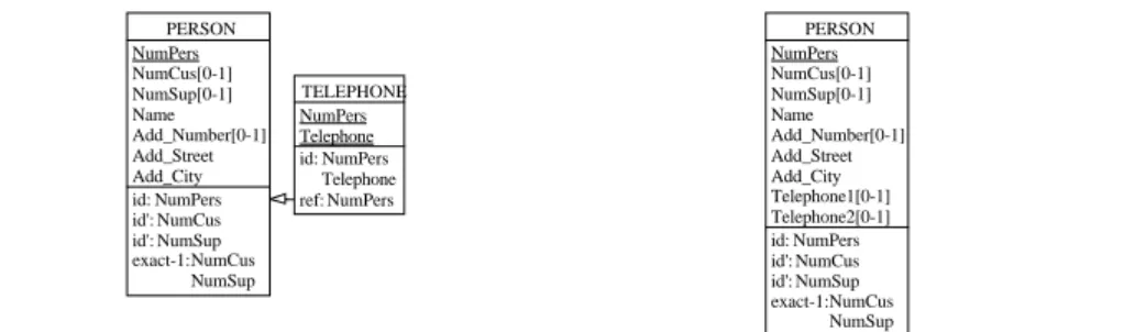
In the example, when the LD0 history (section 3.3) is replayed on a new conceptual schema CS1, the designer does not transform the attribute Telephone into an entity type, that will become the table TELEPHONE (Fig. 6a). He decides to apply the instantiation transformation, according to which a single-valued attribute is introduced to store each value. Telephone is therefore replaced with two optional single-valued attributes:
Telephone1 and Telephone2 (Fig. 6b). The new logical design history LD1 is equivalent
to LD0 except that the signature (Telephone1,Telephone2) ← instanciate(Te-lephone) replaces the T3 signature and the T7 signature is removed. By simply re-playing PD0 on the new logical schema, a new physical design history PD1 is obtained, in which the indexes and storage space specifications related to the old TELEPHONE ta-ble have been automatically discarded.
Fig. 6. Two popular representations of multivalued attribute Telephone.
4.4 Database Conversion
Once the specifications have been updated, the database structure and contents D0 can be converted. The data conversion can be automated thanks to a converter generator. The study of the evolution histories (CE1, LE1 or PE1) allows the generator to locate the mo-difications in the three abstraction levels. A differential analysis of the design histories (LD0, LD1, PD0 and PD1) gives the information to derive the removed, modified or ad-ded physical structures. To shorten the notation, let us call E any evolution history, C0 and C1 any elementary or composed history in the old and in the new branch. In the first scenario, we have: PS0 = PD0(LD0(CS0)) = C0(CS0) and PS1 = PD1(LD1(CS1)) = C1(CS1). In the second scenario, we have: PS0 = PD0(LS0) = C0(LS0) and PS1 = PD1(LS1) = C1(LS1). In the third scenario, C0 and C1 are empty.
According to a definite type of modification appearing in E, three distinct behaviours are possible:
a) Telephone represented by a table in LS0. b) Telephone represented by two columns in LS1.
TELEPHONE NumPers Telephone id: NumPers Telephone ref: NumPers PERSON NumPers NumCus[0-1] NumSup[0-1] Name Add_Number[0-1] Add_Street Add_City id: NumPers id': NumCus id': NumSup exact-1: NumCus NumSup PERSON NumPers NumCus[0-1] NumSup[0-1] Name Add_Number[0-1] Add_Street Add_City Telephone1[0-1] Telephone2[0-1] id: NumPers id': NumCus id': NumSup exact-1: NumCus NumSup
1. In case of creation, the analysis of C1 gives the new physical structures according to the possible transformations applied successively on this object.
2. In case of suppression, the analysis of C0 provides the old physical structures to remo-ve according to the possible transformations applied on this object.
3. The case of modification is more complex. Initially, the new structures are created on the basis of C1. Then, the data instances are transferred from the old structures to the new ones. And finally, the old physical structures are removed according to the analy-sis of C0.
The analysis of E, C0 and C1 let us derive the transformation of data structures and instances of PS0 (i.e., D0) into structures and instances of PS1 (D1). The chain of struc-tural mappings (T parts) drives the schema modification while the chain of instance map-pings defines the way data have to be transformed. These transformations are translated into a converter made up of SQL scripts or programs5 in more complex cases. The trans-lation of schema transformations into SQL scripts has been described in [12].
Some modifications bring about information losses and constraint violations. In these cases, the conversion script produces a query to verify the violation of the constraint and to ensure data consistency. For example, if the designer creates a primary identifier on a previously non-unique column, the table contents can violate the uniqueness constraint, so that the script must store the inconsistent rows, as well as the possible dependent rows in other tables, in temporary error tables. Automating the generation of conversion scripts is always possible, but an user intervention is sometimes necessary to manage ambiguous or conflicting instances.
In the example, the analysis of CE1, C0 and C1 shows that the old table TELEPHONE (in source schema PS0) must be replaced by the columns TELEPHONE1 and
TELEPHONE2 (in target schema PS1). A converter translates this transformation into the
following Oracle script, which converts both the database structure and contents, and which stores the conflicting data, if any, into the table TEL_ERROR.
-- Creation of Telephone1 and Telephone2 ALTER TABLE PERSON ADD TELEPHONE1 CHAR(12); ALTER TABLE PERSON ADD TELEPHONE2 CHAR(12); -- Creation of table TEL_ERROR
CREATE TABLE TEL_ERROR(NUMPERS INT, TELEPHONE CHAR(12)); -- Transfert of data
CREATE OR REPLACE PROCEDURE Trf_data IS CURSOR c1 IS SELECT * FROM PERSON P
WHERE exists(select * from TELEPHONE where NUMPERS=P.NUMPERS); CURSOR c2 IS SELECT * FROM TELEPHONE where NUMPERS=num;
tP c1%ROWTYPE; tT c2%ROWTYPE; num INT; comp NUMBER; BEGIN
FOR tP IN c1 LOOP
comp := 1; num := tP.NUMPERS; FOR tT IN c2 LOOP
IF comp=1 THEN
UPDATE PERSON SET TELEPHONE1=tT.TELEPHONE WHERE NUMPERS=tP.NUMPERS; END IF; IF comp=2 THEN
UPDATE PERSON SET TELEPHONE2=tT.TELEPHONE WHERE NUMPERS=tP.NUMPERS; END IF; IF comp>2 THEN INSERT INTO TEL_ERROR VALUES(tP.NUMPERS,tT.TELEPHONE); END IF; comp := comp + 1;
END LOOP; END LOOP; END;
-- TELEPHONE destruction
DROP TABLE PHONE CASCADE CONSTRAINT;
4.5 Program Modification
Modifying the application programs P0 following database structure modification is clearly a complex task that cannot be completely automated or only in simple cases where the modifications are minor. To characterize the impact of data structure modifications on programs, we defined three kinds of modifications:
• Some structure modifications do not require any modification on the programs. For example adding or modifying physical constructs (on indexes and storage spaces) has no impact on the programs, at least for RDBMS6. The same is valid for the addition of a table or of columns for which no new constraints, such as not null, are defined.7 Some more complex modifications can be absorbed through the view mechanism, if it can rebuild the former data structures.
• Other structure modifications only require minor, and easily automated, modifications of the programs. Such is the case of a table renaming or a value domain extension. • However, many modifications involve deeper modification of the program structure.
They often require a thorough knowledge of the application. In Fig. 2a, if the attribute
CUSTOMER.Account becomes multivalued, it translates into a table in the
correspon-ding logical schema. Following this extension of the schema semantics, the program must either keep its former specification (one must decide how to select the unique ac-count value) or process the multiple acac-counts of each customer (generally by introdu-cing a processing loop). In either case, the very meaning of the program must be coped with, possibly through program understanding techniques. The difficulty lies in the de-termination of code lines that must belong to the new loop.
In most cases, the program modification is under the responsibility of the programmer. However, it is possible to prepare this work by a code analysis that allows locating the critical sections of code. Techniques of program analysis such as pattern searching, de-pendency graphs and program slicing make it possible to locate with a good precision the code to be modified. These techniques have been detailed in [10] and [21].
On the basis of E, C1 and C0 analysis (section 4.4), the schema constructs that have changed can be identified and supplied to the program analysers (dependency graphs ana-lysers and program slicers). The latter locates the code sections depending on these mo-dified constructs. A generator examines the results of the program analysis and produces a report of modifications which would be advisable to apply to the programs under the programmer control.
In the example of the attribute TELEPHONE, the database conversion requires modi-fications of the program structure. Before the modification, the extraction of the telepho-ne numbers of a person required a join operator, while in the telepho-new structure, the values are available in two distinct columns of the current PERSON row. Clearly, the processing of these values must be rewritten manually unless the program had been written in a parti-cularly disciplined way. To locate the code to be modified, the program analysers use pa-rameters based on the table TELEPHONE, its columns and the variables which depend on it.
Despite the intrinsic complexity of program evolution, new approaches are being de-veloped, and can prove promising. One of them is based on wrapper technology8 that
iso-6 This would not be true for legacy databases, such as standard files. 7 Provided the select and insert statements use explicit column names.
lates the application programs from the data management technology. A wrapper is used to simulate the source schema PS0 on top of the new database (schema PS1). The map-pings T and t of the history E are encapsulated in the wrapper instead of being translated into program changes. In this way, the programs access the new data through the old sche-ma, so that the application logic must not be changed. File I/O primitives have to be re-placed with wrapper calls in a one-to-one way, a process that can be easily automated. This approach has been described and explored in [11].
5
Conclusions
The problem of the evolution of an information system, or data-centred application, in-cludes that of the database which is at its core. The requirement evolution is translated technically into the modification of specifications at the corresponding abstraction level. The difficulty lies in the propagation of these modifications towards the other levels and especially to the operational components, namely the database and the programs.
The concepts (transformational modelling, generic specification representation and process traceability) of the DB-MAIN approach are a formal basis for the understanding and resolution of the evolution problems. If the documentation of the system design is available or can be rebuilt by reverse engineering, then the evolution control becomes a formal process. This process can widely be automated as far as the database is concerned. Unfortunately, program modification remains an open problem in the general case. It is however possible to help the programmer to modify the code by automatically locating the sections where occurrences of modified object types are processed.
We have developed a prototype CASE tool for relational database evolution according to the strategy and the scenarios described in this paper. The prototype is developed in Voyager 2 as an add-on of the DB-MAIN platform [22]. It automatically generates the database converters corresponding to any transformation sequence. It also generates the rules to be used by the DB-MAIN program analysers to identify the program code sec-tions that should be modified.
An experiment has been carried out on a medium size database (326 tables and 4850 columns) in a distribution company. The application programs were made up of 180.000 COBOL lines of code distributed among 270 modules (a table appears in seven modules on average). The experiment showed that the time of assisted conversion of the structure, the data and the programs was less than one third of that of the manual process. With the assisted method, an engineer propagated one elementary database modification into the database and the programs in one day versus three days with the manual process. The company saved forty working days for twenty modifications a year while decreasing the risk of error. However, the assisted method required an initial investment of thirty days to rebuild a correct and up-to-date database documentation and to adapt the data conver-sion and program analysis tools.
8 A data wrapper is a procedural component that transforms a database from a legacy model to
another, generally more modern model. It appears as a data server to client applications and makes them independent of the legacy model technology. For instance a set of COBOL files can be dynamically transformed into an object store or into a relational database. Wrappers can automatically be generated by the transformational approach described in this paper. See [19] for more details.
References
1. Al-Jadir, L., Estier, T., Falquet, G., Léonard, M., Evolution features of the F2 OODBMS, in Proc. of 4th Int. Conf. on Database Systems for Advanced Applications, Singapore, 1995. 2. Andany, J., Léonard, M., Palisser, C., Management of Schema Evolution in Databases, in
Proc. of 17th Int. Conf. on VLDB, Barcelona, 1991.
3. Batini, C., Ceri, S., Navathe, S.B., Conceptual Database Design - An Entity-Relationship Approach, Benjamin/Cummings, 1992.
4. Bellahsene, Z., An Active Meta-Model for Knowledge Evolution in an Object-oriented Da-tabase, in Proc. of CAiSE, Springer-Verlag, 1993.
5. Brown, A., Morris, E., Tilley, S., Assessing the evolvability of a legacy system, Software En-gineering Institute, Carnegie Mellon University, Technical Report, 1996.
6. Hainaut, J.-L., Chandelon, M., Tonneau, C., Joris, M., Contribution to a theory of database reverse engineering, in Proc. of WCRE, IEEE Computer Society Press, Baltimore, 1993. 7. Hainaut, J.-L., Englebert, V., Henrard, J., Hick, J.-M., Roland, D., Evolution of database
Ap-plications: the DB-MAIN Approach, in Proc. of 13th Int. Conf. on ER Approach, Manches-ter, 1994.
8. Hainaut, J.-L., Specification Preservation in Schema transformations - Application to Se-mantics and Statistics, Data & Knowledge Engineering, Vol. 19, pp. 99-134, Elsevier, 1996. 9. Hainaut, J.-L., Henrard, J., Hick, J.-M., Roland, D., Englebert, V., Database Design
Recove-ry, in Proc. of 8th CAiSE, 1996.
10. Henrard, J., Englebert, V., Hick, J.-M., Roland, D., Hainaut, J.-L., Program understanding in databases reverse engineering, in Proc. of Int. Conf. on DEXA, Vienna, 1998.
11. Henrard, J., Hick, J-M. Thiran, Ph., Hainaut, J-L., Strategies for Data Reengineering, in Proc. of WCRE'02, IEEE Computer Society Press, 2002
12. Hick, J.-M., Evolution of relational database applications: Methods and Tools, PhD Thesis, University of Namur, 2001. [in French]
13. Jahnke, J.-H., Wadsack, J. P., Varlet: Human-Centered Tool Support for Database Reengi-neering, in Proc. of Workshop on Software-ReengiReengi-neering, 1999.
14. Jarke, M., Nissen, H.W., Pohl, K., Tool integration in evolving information systems environ-ments, in Proc. of 3rd GI Workshop Information Systems and Artificial Intelligence: Admi-nistration and Processing of Complex Structures, Hamburg, 1994.
15. Jensen, C., and al., A consensus glossary of temporal database concepts, in Proc. of Int. Workshop on an Infrastructure for Temporal Databases, Arlington, 1994.
16. Nguyen, G.T., Rieu, D., Schema evolution in object-oriented database systems, in Data & Knowledge Engineering (4), Elsevier Science Publishers, 1989.
17. Roddick, J.F., Craske, N.G., Richards, T.J., A Taxonomy for Schema Versioning Based on the Relational and Entity Relationship Models, in Proc. of 12th Int. Conf. on the ER Ap-proach, Arlington, 1993.
18. Shneiderman, B., Thomas, G., An architecture for automatic relational database system con-version, ACM Transactions on Database Systems, 7 (2): 235-257, 1982.
19. Thiran, Ph., Hainaut, J-L., Wrapper Development for Legacy Data Reuse, in Proc. of WCRE, IEEE Computer Society Press, 2001
20. van Bommel, P., Database Design Modifications based on Conceptual Modelling, in Infor-mation Modelling and Knowledge Bases V: Principles and Formal Techniques, pp 275-286, Amsterdam, 1994.
21. Weiser, M., Program Slicing, IEEE TSE, Vol. 10, pp 352-357, 1984. 22. http://www.db-main.be/ and http://www.info.fundp.ac.be/libd.