En vue de l'obtention du
DOCTORAT DE L'UNIVERSITÉ DE TOULOUSE
Délivré par :
Institut National Polytechnique de Toulouse (INP Toulouse) Discipline ou spécialité :
Génie Electrique
Présentée et soutenue par :
M. GURVAN JODIN le mercredi 25 octobre 2017
Titre :
Unité de recherche : Ecole doctorale :
Hybrid electroactive morphing at real scale, application to Airbus A320
wings
Génie Electrique, Electronique, Télécommunications (GEET)
Laboratoire Plasma et Conversion d'Energie (LAPLACE) Directeur(s) de Thèse :
M. JEAN FRANCOIS ROUCHON MME MARIANNA BRAZA
Rapporteurs :
M. JULIAN HUNT, UNIVERSITY COLLEGE LONDRES M. LIONEL PETIT, INSA LYON
Membre(s) du jury :
M. LIONEL PETIT, INSA LYON, Président
M. FRANK THIELE, TECHNISCHE UNIVERSITAT BERLIN, Membre M. JEAN FRANCOIS ROUCHON, INP TOULOUSE, Membre
M. JEAN-MICHEL SAUCRAY, AIRBUS FRANCE, Membre Mme MARIANNA BRAZA, INP TOULOUSE, Membre
Acknowledgements
Before French acknowledgements, I would like to particularly thank the member of the jury for their devoted time and advice.
Je m’adresse maintenant en français pour remercier mes directeurs Jean-François et Marianna. Ils m’ont guidé et fait coniance en me donnant une autonomie dans ce projet. Je remercie également les ingénieurs d’Airbus avec qui nous avons tra-vaillé et qui ont cru en ce projet : Christophe Cros, Alain Fontaine, Jean-Michel Saucray et Denis Descheemaeker.
Tout le travail que je présente n’aurait été possible sans une assistance sci-entiique et technique de haut niveau et très professionnelle par les personels du Laplace, de l’IMFT et de l’INP-ENSEEIHT : Dominique Harribey, Christophe Korbuly, Sébastien Cazin, Moïse Marshal, Pierre Elyakim, Robert Laroche, ... Une pensée certaine aux personnels administratifs que j’ai bien embêté avec mes missions et commandes en tout genre, mais qui m’ont toujours aidé avec le sourire ! Pour leur conseils et leur présence, je tiens à remercier les membres des équipes GREM3 et EMT2.
Je n’oublie pas les stagiaires “gentiment exploités” avec qui j’ai eu plaisir à tra-vailler. Pour toutes les parties de Haxball, les chocos, les verres, mais également les discussions scientiiques et professionnelles, un grand merci aux doctorants, post-doc et ingés qui m’ont supporté pendant ces trois années. Je souhaite transmettre des mots d’amours et des poulpis pour ma compagne et plus généralement toute ma famille pour leur support durant cette période importante pour moi.
Contents
i iii 1 Acknowledgements Contents Introduction1 State of the art 5
1.1 From ornithology to aeronautics . . . 5
1.2 Industrial point of view on aircraft morphing projects . . . 9
1.3 Airlow physics around an airfoil and its control . . . 14
1.4 Electroactive smart material for actuators . . . 20
1.5 Smart and active structures for morphing aircrafts . . . 30
1.6 Conclusion and originality of the proposed work . . . 33
2 An electroactive hybrid morphing wing at reduced scale for wind tunnel experiments 35 2.1 Introduction . . . 36
2.2 Camber control actuator . . . 40
2.3 Higher Frequency Trailing Edge design . . . 56
2.4 Features and making of the hybrid electroactive wing prototype . . 64
2.5 Electrodynamic characterization . . . 67
2.6 Chapter conclusion . . . 78
3 Wake dynamics of the hybrid morphing wing prototype by TR-PIV and force measures 79 3.1 Introduction . . . 80
3.2 Wind tunnel model . . . 84
3.3 Hybrid morphing experiment overview . . . 89
3.4 Wake dynamics and control mechanisms . . . 92
3.5 TR-PIV measurements and characterization of HFVTE efects on airlow . . . 97
3.6 Proper orthogonal decomposition of the wake low . . . 103
3.7 Spectral analysis of low velocity . . . 124
3.8 Efect of high frequency actuation on aerodynamic loads . . . 129
3.9 Conclusion . . . 134
4 Design through optimization: true scale cambered control lap 137 4.1 Introduction . . . 138
4.2 Morphing wing concept and modeling . . . 140
4.3 Actuator modeling . . . 146
4.4 Skin technologies and modeling . . . 154
4.5 Optimization problem . . . 159
4.6 Optimization results . . . 163
4.7 Conclusion and outlooks . . . 171
Conclusion 173 Outlooks . . . 175
Related publications and contributions . . . 176
A Wind tunnel experiment appendices 183 A.1 Experimental result validation: statistical convergence of the PIV . 183 A.2 Experimental result validation: statistical convergence of the balance183 A.3 Parasite drag efect . . . .186
B True scale cambered control lap appendices 187 B.1 Optimization results of the lap with elastic skin and elastic beam hinges . . . 187
B.2 Optimization results of the lap with feathers and gliding bearings . .189 B.3 Optimization results of the inal chosen lap design . . . 191
Nomenclature
u2, v2 Time average of the stream-wise and crosslow component of the Reynolds
tensor.
A, a∗ HFVTE actuation amplitude (mm). a∗
= Ac is the dimensionless amplitude.
c chord length
D, D, CD Drag force, time average drag, drag coeicient CD = 1/2SρUD 2
∞. With ρ
the air density, S the reference wing section.
Fa, fa∗ HFVTE actuation frequency (Hz), dimensionless actuation frequency f ∗
a = FUa∞c
L, L, CL Lift force, time average lift, lift coeicient CL = 1/2SρUL 2
∞. With ρ the air
density, S the reference wing section.
M Mach number: M = U/v where U is the considered velocity and v the
corresponding sound velocity.
St Strouhal number. St = Uf ·c
∞, with f the frequency in Hz.
u, v Stream-wise (u), respectively crosslow (v) luctuating component of the
low velocity normalized in relation with U∞. u = U − U, v = V − V
U, V and U, V Stream-wise (U), and crosslow (V ) component of the low
veloc-ity normalized in relation with U∞. U, V are the time averages of the
components.
U∞ free stream velocity (m/s)
CAD Computer Aided Design. FEA Finite Element Analysis
HFVTE Higher Frequency Vibrating Trailing Edge KH Kelvin-Helmholtz
MAV Micro Air Vehicle
MFC piezoelectric Macro-iber Composite Patches. POD Proper Orthogonal Decomposition.
PSD Power Spectral Density.
Re Reynolds number relative to the chord c. Re = cU∞
ν where ν is the kinematic
viscosity of the air.
Sk Stokes number, Sk = ρρd2ρU∞
18µδc , where µ is the dynamic viscosity of the luid,
ρρ is the density of the smoke particles, δc is the characteristic length i.e.
the model chord and dρ is the diameter of the particles
SMA Shape Memory Alloy.
TNT Turbulent / Non Turbulent Interfaces TRL Technology Readiness Level
Introduction
Future aircrafts will be faster, safer, more silent, more comfortable, more environ-mental friendly and less expansive. This utopian objective has been evolving since the beginning of planes, in the very end of the 19th century. Firstly inspired from lying animals, the demand for carrying people and goods further and faster has led to large, rigid, fast and powerful aircrafts.
Nowadays aircrafts have ixed wing geometries. The unique airfoil proile re-sults from an optimal compromise for some cruise light states. Giving the ability of aircraft wings to change their shape – like birds do – improves their aerodynamic performance. The particular properties of bird feathers allow them to vibrate within the airlow. How does this interact with the low turbulence? And can this be of help for improving future aircraft performance? Thus, the photomontage of Figure 0.1 illustrate our objective.
Within this context, the LAPLACE and the IMFT laboratories work together
Figure 0.1: Photomontage made from Airbus A380 and seagull. MT180, a national scientiic popularization competition, 2016.
on the research platform SMARTWING1. They have been supported by the Réseau
thématique de recherche avancée (RTRA) – part of the Foundation STAE – and the Direction générale de l’armement (DGA). Eforts on electroactive morphing have been focused on micro- and nano-air-vehicles to improve their performance (Rouchon et al. [Rou+11]). Then an electroactive bending plate (Chinaud et al. [Chi+14]) and a small wing with electroactive vibrating trailing edge (Scheller et al. [Sch+15]) have been studied. Afterwards, a small electroactive wing with both camber control and vibrating trailing edge has been investigated, (Scheller et al. [Sch]). It has been the irst hybrid electroactive wing prototype.
Based on this work, this thesis will focus on both aerodynamics and electrome-chanics. A multidisciplinary approach is proposed in order to understand further the hybrid electroactive morphing concept. Chapter 1 introduces a background on the diferent ields concerned by this thesis. Supported by Airbus, a hybrid electroactive wing is designed, made and characterized in Chapter 2. To inves-tigate low dynamics and quantify aerodynamic performance modiications, wind tunnel experiments are investigated in Chapter 3. Towards true aircraft scale, the design of a realistic morphing lap for an Airbus A320 is detailed in Chapter 4. Contributions and last elements are summed up in the conclusion 4.7.
Following the previous work of our research groups, this thesis is the continua-tion of the thesis of Johannes Scheller [Sch15]. Johannes made a proof of concept regarding hybrid electroactive morphing. The contributions of the present thesis is decomposed threefold:
• We propose design models for electroactive hybrid morphing wings. Starting from the material models, analytical and inite element models are proposed for both camber control and vibrating trailing edge. Models’ achievements and limits are presented. The wing is built and instrumented for wind tunnel experiments. Impact of control laws on power consumption, electrodynamic characterization and sensor relevances are emphasized. The correlation be-tween embedded pressure sensor measures and aerodynamic performance improvements is an original contribution.
• An experimental investigation of hybrid morphing in wind tunnel is per-formed. Reliability of the actuators is assessed. Wake dynamics is analyzed, and the impact of morphing is described. We propose a physical explanation based on Hunt’s theory. For the irst time, force measurements (i.e. lift and drag) modiications due to hybrid morphing are outlined.
• We propose a design process for a true scale morphing lap for A320, actuated with smart materials. The proposition consists in a camber control function
fulilled by a macro actuator. This macro actuator – including internal actu-ators based on shape memory alloys – is designed through an optimization algorithm. Diferent technologies for skins and articulations are compared. The internal electroactive actuators are modeled. A mutli-objective genetic algorithm is used to ind the best compromise between performance, weight, power consumption and cycle life.
CHAPTER
1
State of the art
“Nature is a library, read it instead of burning it.” “La nature est une bibliothèque, lisez-la au lieu de la brûler.”
Idriss Aberkane
Abstract This manuscript describes a multidisciplinary work.
This chapter relates a few examples from diferent sci-entiic ields to give a background to the present work. The following path is observed: beginning with nature observation and bioinspiration, morphing is deined and industrial research projects on aircraft morphing are pre-sented. Airlow physics around airfoils are mentioned to deine actuators’ aims. A speciic attention is paid to electroactive smart materials before dealing with appli-cation of actuated structure.
1.1 From ornithology to aeronautics
1.1.1 Ornithology for bioinspiration
It is commonly believed that planes are inspired from birds. A famous example is the aircraft Éole of Clément Ader. This aircraft was inspired from lying foxes, which are bats. By the way, bats are mammals, not birds... Ornithology is the discipline that studies the birds. This section briely introduces few researches on birds that can be useful to design future aircrafts.
Numerous birds’ wings have alulae, which correspond to their thumbs. The alula has been studied in diferent ways. Diferent functions are attributed to the alulae and have their equivalent on aircrafts. Lee et. al. [Lee+15] performed PIV experiments on magpie wings. Performance of a wing with retracted alula is compared to a wing with extended alula. Figure 1.1 presents some of thier results. It has been shown that alula feathers create tip vortices that delay the detachment of the low on the suction side of the wing. The complex structure of
Figure 1.1: From Lee et. al. [Lee+15]. Velocity proiles with and without alula, time average streamwise velocity and artist’s impression of the alula efect on the bird.
such 3D low instabilities have been studied by Braza et al. [BFP01]. This allows the birds to light at low speed with high angle of attack. It helps to land. This hyperlift function is analog to aircraft slats. The alula contains feathers that gives information on airlow. Brown et. al. [BF93] have looked at the neural signals coming from the wing nerves when the alula is exposed to airlow. They conclude that alula returns information on stall and wind velocity.
Belong their lat and esthetic look, feathers are complex and have multiple utilities. They are categorized by shape and function, [Orn13]. For example, the irst remiges compose the wing and are hold on the bones, they carry aerodynamic loads. The secondary remiges can not hold the aerodynamic loads but gives the airfoil shape of the wings. The feathers are porous and can glide on each other to allow the bird to change its wing’s shape. In section 4.4.2 of this manuscript, birds’ feathers inspire an innovative concept of skin and feathers for aircraft. Feathers can provide low noise light, like the well known owl hunting during the night. Studies have shown that the feathers of the owls are hairy, thus generating small vortices that change the low dynamics of their wakes and then decrease their noise, Lilley et al. [Lil98]. The fact that birds have numerous feathers with diferent sizes prevent them from aeroelastic instabilities, like lutter. Clarke et. al. [CP15] measured lutter frequencies for diferent feathers. As the frequencies are spread,
aerodynamics of wings, porous wings, passive and active low control as well as structural characterization of structural stifness and strengths are introduced.
1.1.2 Basis of light physics and performance
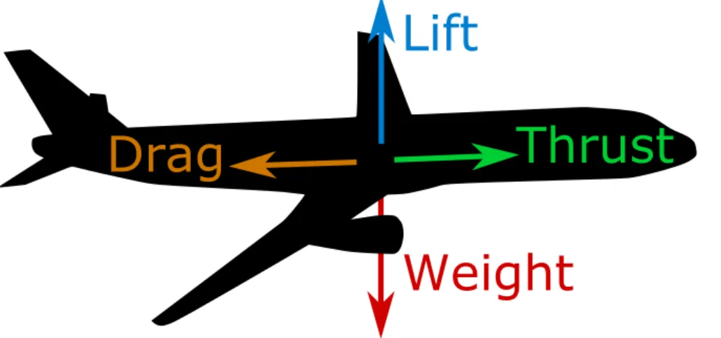
Before focusing on aircraft performance enhancement, the basis of light physics must be introduced. The book writen by Anderson [And10] is a succeeded intro-duction to aerodynamics. Figure 1.2 schematically represents the force balance of a lying aircraft. Notice the torques are not represented, as they are secondary for the following explanation. To stay at constant altitude, the weight W must be compensated by the lift L. A large part of the lift is due to the wing. The wing and the other component of the aircraft – with their shapes and sizes – generate the drag D. To light at constant velocity, this drag is opposed by the thrust T . The thrust comes from the engines or propellers for aircrafts. For birds, the wing motion is in charge for both lift and thrust, but lapping motions are out of scope for this manuscript.
On one hand, considering a whole light, the weight is not constant. Firstly depending on the variable boarded payload, aircrafts’ weights decrease all along the light as they literally burn the fuel. On the other hand, the wing aerodynamic performance are often characterized by the lift over drag ratio (LoD). Also called
aerodynamic inesse, this criteria depends on light conditions, angle of attack α,
notably Mach number M and altitude a (L/D = LoD(α, M, a)). The angle of attack control directly the lift, so that the LoD ratio is also expressed L/D =
LoD(L, M, a). Thus, as the expansive fuel consumption is directly linked to the
Lift
Thrust
Drag
Weight
Figure 1.2: Illustration of the force balance of a lying aircraft along a steady without acceleration trajectory.
engines’ thrust, equation 1.1 expresses the link between aerodynamic performance and fuel burnt.
L D = LoD(L, M, a) L = W D = T T = W LoD(W, M, a) (1.1)
This equation explains why it is so important to limit the weight. The power consumption of aircrafts is directly linked to aerodynamic performance. An im-provement in aerodynamic performance can be achieved by decreasing the drag or increasing the lift at constant drag and angle of attack.
To go further on this analysis, nowadays aircraft wings “are designed for a compromise of good performance at a variety of light conditions” as say Bur-dette et. al. [Bur+15]. It results that the aircrafts always ly at sub-optimal con-ditions, even during cruise.
The previously described elements concern the working principle of aircraft. It is also important to notice the way of light control assessed by movable surfaces for planes, or morphing wings and tails of birds. Basically, the main control surfaces control the aircraft attitude (inclination). To introduce some vocabulary, ailerons are located close to the wing tips. They control the roll and can be assisted by spoilers. The elevators, located on the horizontal stabilizer, control the pitch; whereas the yaw is controlled by the rudder, mounted on the vertical stabilizer.
Flaps and slats are secondary control surfaces. They fulill coniguration control
function. This function consists in adapting the wings’ areas and shapes to the light conditions. As birds enlarge their wings and extend the alulae at low speed, aircrafts extend slats and laps for take of and landing. Control trimming surfaces and other control surfaces like air brakes are not discussed here for brevity purpose.
Finally, a short attention is given to noise sources. It is known that aircraft noise is mainly due to landing gears and slats during landing, Dobrzynski et al. [Dob10]. Take of noise is dominated by engines. As silent birds hunt by night, a
1.2 Industrial point of view on aircraft
morphing projects
1.2.1 Deinition of morphing
The deinition of aircraft morphing can be quite subjective. An articulated struc-ture can be understood as a morphing strucstruc-ture for some people, whereas the deformation has to be smooth and seamless from the point of view of other re-searchers...
In 2010, the NASA deined that “Aircraft morphing is: • large shape change,
• smooth, seamless shape change, • reconigurable aircraft,
• reconigurable aircraft using unconventional control surfaces, • adaptive wings,
• real-time, seamless wing shape control,
• smart structures embedded in wings for passive or active shape control, • any kind of wing adaptation,
• a crazy idea. ”
Additionally, Stefen BAUSS from Airbus deines in 2013 that “Aircraft morphing is real-time adaptation to enable mutli-point optimized performance in air vehicles”. Then morphing aims four objectives:
1 Improve aircraft performance to expand the light envelope (mission segment optimization, noise reduction);
2 Replace conventional control surfaces for improved light control and perfor-mance;
3 Drag reduction for increased range, fuel economy;
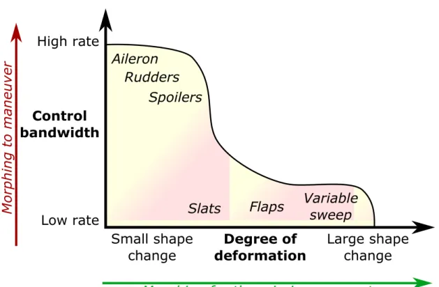
4 Flutter control, vibration control, passenger comfort, safety, structural health. From an aircraft manufacturer point of view, the distinction between the criti-cal maneuver functions and the coniguration functions is important as they require diferent actuation frequencies and amplitudes. Figure 1.3 represents the diferent control surfaces as a function of deformation velocities and amplitude. This chart is not exhaustive, new functions can be added. For instance, dynamic low / tur-bulence control can require small amplitudes at low or high frequency.
Finally, the most important about morphing deinition is that “The ultimate
goal of morphing in an aircraft is to transform the airlow. Not the structure”
(Stefen BAUSS). Actually, beyond the engineering, the science, the environmen-tal impacts linked to morphing, there are commercial reasons. Due to competition between aircraft manufacturers, aircrafts have to be more and more eicient. This
High rate
Low rate
Small shape
change
Large shape
change
Slats
Flaps
Variable
sweep
Aileron
Rudders
Spoilers
Control
bandwidth
Degree of
deformation
Morphing for the mission segment
M
o
rph
in
g
to
ma
n
e
u
v
e
r
Figure 1.3: Representation of aircraft functions in the degree of deformation-deformation rate plane. From Stefen BAUSS (Airbus) presentation in 2013. efectiveness is partially due to aerodynamic improvements. The potential of mor-phing has to be assessed by luid dynamic studies. But to make it happen, all the work relies on the structure and the actuators.
1.2.2 Thorough research projects on morphing
Large research projects with industrials have addressed aircraft morphing. These projects with substantial funds deal with conventional and new technologies to develop credible solutions – i.e. at high Technology Readiness Levels (TRL). In-dustrial constraints like failure management, maintenance are dealt. Complete aerodynamic studies linked to aircraft design are proceeded. The gains are evalu-ated for a whole aircraft – i.e. they are not limited to a 2D airfoil aerodynamic
1.2.2.1 SARISTU
The European research program SARISTU1 focuses on operating cost reductions
as well as on improving the aerodynamic performance. Three work packages are linked to morphing, embedded in the demonstrator visible in Figure 1.4.
One work package of SARISTU deals with a morphing wing trailing edge. Lead by CIRA – The Italian Aerospace Research Centre – the adaptive camber wing aims to stay at minimal drag, as the best coniguration changes with reference to actual light mission and during the light. The device is based on servomotors driving an articulated structure, [Dim+16]. Elastomeric joints with foam have been designed to have smooth deformed shapes.
DLR is in charged of the enhanced adaptive droop nose for a morphing wing. This active leading edge is based on the work done during the previous European project SADE. This work package states that a feasible solution to enhance per-formance could be the laminar wing to reduce drag during take-of, cruise and landing. Therefore a morphing and gapless droop nose device is needed to provide laminar low. Such a device would additionally decrease the overall noise emission. Aeronautic constraints concerning the design like bird strikes, failure analysis, de-icing devices and lightning protection are developed. As presented in [Kin+16], the system relies on a servomotor driving a torque shaft which is linked to a simple optimized internal mechanism. This mechanism deforms the speciically studied morphing skin. The total mass of this system is evaluated to 14 kg, where 50% belongs to the motor. Having a localized actuator concentrates the mass, the distribution of the actuation can be a possible way to reduce mass.
The third morphing device corresponds to a Wingtip Active Trailing-Edge – WATE – directed by EADS Innovation Work. It consists in a control surface on the wingtip with speciic lexible elastomeric joints. This allows the wingtip shape to be smooth and continuous despite the rotation of the control surface. This study demonstrates the ability of speciic elastomer to work at low temperature, [Nag+16].
Michael X. Meyer from Airbus, announced2that morphing in SARISTU inally
exhibits no gain. Indeed some aerodynamic enhancements are true but the global gain is null (with commercial factors and the added mass and systems).
1.2.2.2 Variable Camber Continuous Trailing Edge Flap
The VCCTEF concept has been developed in 2010 by NASA. This concept con-sists in replacing the wing trailing edge by a morphing trailing edge all along the
1http://www.saristu.eu
2Keynote at 52nd International Conference on Applied Aerodynamics, Lyon, France, 2017
Figure 1.4: Picture of the SARISTU wing prototype from [Nag+16]. It embeds the diferent demonstrators of the assessed technologies of the project.
span. The camber can be adapted to diferent spanwise values. Diferent numeri-cal [KN14] and experimental [PML14] studies on aerodynamics or actuators have taken placed. Control strategies also have been studied. The concept has diferent implementation: an articulated trailing edge with 3 hinges [PML14] or a continu-ous chordwise deformation [KH08]. This last solution – implemented by the irm Flexsys – relies on a gliding pressure skin to stand the skins’ length changes. An optimized truss structure is made inside the lap. This truss is actuated thanks to a conventional hydraulic or electric actuator. A lap based on this last technology has been tested during light test campaigns by NASA and Flexsys on a business jet, as visible in Figure 1.5, [KFC16] [Cum+16].
Figure 1.5: Picture of the Gulfstream III SubsoniC Research Aircraft Testbed, with the morphing lap prototype from [Mil+16]
.
shape memory alloy (SMA) actuators.
As a irst instance, the SAMPSON Smart Inlet is a full scale demonstrator of F-15 ighter aircraft inlet tested in a realistic environment. Funded by DARPA, the main objective is to replace the current hydraulic actuator used to rotated the cowl, changing the inlet geometry. Sixty Ni-Ti wires are bundled together to provide 90,000 N axial force output. This system has been tested in a NASA transonic wind tunnel, [PDW02].
Another interesting example regarding commercial aircraft is introduced by the Boeing Company [CM16]. This project consists in a SMA actuator that extends a miniature plain lap on the wing trailing edge, after the aileron. The purpose of such small lap was noise reduction with mixed results, but the design process to develop SMA actuator with a high TRL is very interesting. A hydraulic bake and redundant system is designed to assist the SMA torsion rod. This rod is made of an alloy speciically developed for the application, taking ageing issue into account.
These two examples draw the following conclusion: new actuator technologies are welcome to industrial application if the gains are true. The lack of knowledge concerning failure cases and ageing, the adaptation of the existing systems have to be addressed irst. A system approach is needed to estimate the true gains, one cannot simply replace an existing actuator by a new one based on innovative technology. The More Electric Aircraft was promising, but as the failure cases are
diferent compared to existing hydraulic actuators for instance, a simple upgrade is not possible and the functions must be re-engineered.
1.3 Airlow physics around an airfoil and its
control
1.3.1 Flow dynamics around an airfoil
For centuries, luid mechanics have been intensively studied and some mysteries are still unsolved. A popular example is Clay Mathematics Institute that ofers a 1 million dollar award for an analytic solution of the Navier-Stokes equation. One very developed ield of luid mechanics is aerodynamics with application to aircrafts. Anderson [And10] introduces the design of aircraft and the modeling of airlow around airfoils.
1.3.1.1 Flow around an airfoil
It is explained that boundary layers – close to the wing surface – is dominated by viscous efects. The low is rotational, i.e. the rotational of the low velocity ield is not null. On the opposite, low far from the surface is dominated by inviscid efects, non-rotational. The interaction and interface between these two behaviors is characterized by turbulent/laminar low, attached/detached low. One can note that a detached low is not mandatory turbulent as well as an attached boundary layer is possibly turbulent. These phenomena can be associated to ranges of dimensionless numbers like Reynolds number (Re) or Mach number (M∞). Their
deinitions are reminded in equation 1.2. c is the airfoil chord, U∞ is the free low
velocity (far upstream of the wing), ν is the kinematic viscosity of the air and
Usound is the sound velocity in the wing environment.
Re = c · U∞ ν M∞ = U∞ Usound (1.2) Figure 1.6 schematically describes diferent low behaviors for diferent shapes and Reynold numbers. Drag forces are represented with a distinguish between skin friction – coming from the integration shear forces on the skin – and pressure drag
Figure 1.6: Reynolds and shape efects on wings and bluf bodies, from Ander-son [And10]
wake is responsible for a large pressure drag. Increasing the velocity (i.e. Reynolds number) increases the drag, but the distribution between pressure and friction drag also changes. For example, increasing the Reynolds number around the cylinder Figure 1.6b to the case in Figure 1.6e change the drag distribution: the separation point goes further by increasing the Reynolds number to so called super-critic regimes. A thorough analysis of the forces related to the wake dynamics can be found in [BCM86] and [PB98].
Mach number is also a relevant dimensionless number that characterize airlows. This ratio quantiies the importance of compressibility efects. As presented in Figure 1.7, shockwaves occurs at high Mach lows. Subsonic lows 1.7a, does not exhibit shockwaves. Their physics are diferent from transonic lows 1.7b. Current jet airliners cruise at Mach numbers around M∞ ≈ 0.8. Locally on suction side
– and sometimes on pressure side – a shockwave appears. This shockwave can oscillate, thus drastically afecting the wake dynamics, as investigated by Szubert et al. [Szu+16]. Figure 1.7c informs that the physics can be very diferent with a small change in Mach number in transonic conditions.
1.3.1.2 Wake dynamics
As represented by circular arrows in Figure 1.6, the wake presents vortices. At irst sight, these vortices appear purely random and chaotic. But intensive research demonstrated that coherent vortices can be identiied by statistic characteristics within a chaotic wake. The two most representative vortices present in the wake of a wing are named after famous scientists: the Von Kármán (VK) and the Kelvin-Helmholtz (KH) vortices.
The KH vortices looks like breaking waves in the sea. They occurs in presence of velocity shear. They are characterized by vortices rotating in the same direction. The VK vortex street consists in a repeating of alternative vortices. They come from the unsteady separation of low around the airfoil. These two vortices are periodic and their sizes, shedding frequencies and locations have been studied. For instance, Yaru et al. [YSK06] have experimentally studied the boundary layer and wake dynamics of a NACA0025 airfoil at diferent Reynolds number (up to Re ≈ 150, 000). Another example is the numerical study of Hoarau et al. [Hoa+03]. The unsteady computation of airlow around a NACA0012 airfoil has been performed in 3D.
In order to improve simulation accuracy, Hunt et al. [Hun+16] proposed an explanation and model for the luctuating interfaces between turbulent-non tur-bulent low. These interfaces are present in a wing wake, the link between the
M∞ < 0.8
∞
∞
(a) Subsonic low
∞
0.8 < M∞ < 1
∞
(b) Transonic low with M∞< 1
∞ ∞ 1 < M∞ < 1.2 Tra iling -edg e sh ock Bo w s ho ck
(c) Transonic low with M∞> 1
Figure 1.7: Compressibility efects on wings, from Anderson [And10]. formance. More details are reported in section 3.4.
1.3.2 Flow control and turbulence control
1.3.2.1 Deinitions
Based on the previously described low dynamics, it is easily comprehensible that low instabilities cause noise, vibrations and participates in the average forces on the structures. A luid mechanics’ ield called low control attempts to limit the unwanted phenomena. Because of the non-linearity of the luid dynamics, a small action can have important efects. This can be an important advantage so that Professor Israel J. Wygnanski deines low control as a small energy introduction in the low, to expect a large change in low behavior.
Therefore, low control consists in implementing one or several
vices at a relevant position. Activating this actuator in the right conditions, at given aerodynamic conditions produces the wanted efect: shear layer turbulent en-ergy reduction, preventing dynamic stall, noise reduction, drag reduction, ... The device can be a passive device on the surface (i.e. vortex generator, laminar skin) or actuators that locally change the shape, heat, impose velocity (by blowing or sucking, by vibrating, with plasma actuators, ...).
Considering the proposed approach of this manuscript, a distinction is made between the low control strategies and the turbulence control proposed here. Pre-vious studies of IMFT and LAPLACE laboratories – like Szubert [Szu15] and Scheller [Sch15] – prioritize an approach close to the vortex physics. This philoso-phy consists in discriminating the vortices responsible for the unwanted phenomena and attempt to eliminate them, for the beneit of more proitable vortices. This methodology can lead to also use actuators related to low control, but the intro-duction can be lower as the aim is to manipulate the small vortices that will cause the expected low modiications.
1.3.3 Research examples
The airfoil performance is very sensitive to its shape. A morphing aileron consisting in a smooth and continuous deformation of the airfoil to increase the camber is much more eicient than an articulated aileron. The boundary layer dynamics of a smooth morphing shape has been studied by Koreanshi et al. [K+14]. The inluence on lift and drag is also observed in diferent experiments, with advantage for the continuous morphing shape, as related by Ohanian et al. [Oha+12].
Considering low control, a few examples are discussed. Firstly, passive low control. A passive low control consists in a device with a speciic shape that is added to the existing one to increase performance. A irst example is the addition of hairs on a cylinder. Inspired from hairy plants, the hairs interacts with the wake and reduces the instability, as studied by Kunze et al. [KB12] Another example is the vortex generator located on wings’ laps to increase the lift and/or delay the dynamic stall by preventing the detachment. Lin [Lin02] draws a review on these small aerodynamics appendages located on the suction side of laps. The main advantage of these devices is their easy implementation and robustness; but the main drawback is the lack of adaptability: the optimal shape depends on aerodynamic conditions and can degrade performance during other light states as they correspond to of-design conditions.
Secondly, active low control. The textbook case is a low induced cavity reso-nance, as depicted in Figure 1.8. A review written by Cattafesta et al. [Cat+03]
L
y
x
Feedback
Receptivity CharacteristicsSource
δ
D
λ Turbulent
Boundary Layer
Figure 1.8: Active low control low induced cavity resonance, from Cattafesta et al. [Cat+03].
mechanical, piezoelectric devices or luidic oscillating jets. Active oscillating laps and plasma actuators can also be used. Applying high voltage between two elec-trodes on the wing ionize the surrounding air that becomes a plasma attracted by the electrodes. A large number of studies are related to low control applied to aircraft. To give just one example of active low control on an airfoil, Inaoka et al. [Ina+15] investigates in wind tunnel the efect of active vortex generators mounted close to the leading edge of a NACA0012 airfoil. For diferent Reynolds number, the actuated vibration frequency of the vortex generators was selected close to the vortex shedding frequency. An active control was set to activate these active devices to prevent the stall. The main advantage of the active devices is if the implementation is not too much invasive, they can be switched of during of-design conditions. If the phenomena are well understood, the actuation can be adapted to the low condition to extend the aerodynamic range where gains can be expected. But the main drawback is the require power to supply the actuators. If the aim of such active control is to decrease drag, the power consumption have to be much lower than the saved energy due to the drag reduction. This balance is not obvious.
1.4 Electroactive smart material for
actuators
1.4.1 Smart materials and electrocative materials
Wikipedia eiciently deines smart materials in one sentence: They are designed materials that have one or more properties that can be signiicantly changed in a controlled fashion by external stimuli, such as stress, temperature, moisture, pH, electric or magnetic ields. According to Ferreira et al. [FNM16], the smart materials are stimuli responsive materials belonging to the larger family of the multi-functional material systems. This large family contains designed materials with diferent scales and hierarchies, including composites and materials assessing diferent functions (sensing, actuating, self-healing, self-assembling, energy har-vesting, ...).
Amongst the smart materials, this manuscript focuses on electroactive materi-als. Electroactive materials are here broadly deined as materials that convert a mechanical solicitation to an electrical solicitation and/or vice versa. This means that a material actuated by temperature encapsulated with a resistive electric wire, a material activated by magnetic ield inside a coil or an electric-ield responsive material with electrodes are considered as electroactive materials.
1.4.1.1 Review of some electroactive materials
This section draws a short review of electroactive materials. The following nota-tions are used to compare the materials: ϵact, σact correspond respectively to the
maximum strain and stress due to actuation. Wact/Pact stand for an order of
mag-nitude of mass-speciic output energy/power. Eact stands for applied electric ield,
Hact for magnetic ield, Tact◦ for temperature, Vact for applied voltage. The letter
ϕ
precedes a short explanation of the physical principle of the smart material.Dielectric elastomers
Common material: silicone based Life cycle: 4 − 40M cycles
Max. ϵact ≈ 50%, σact ≈ 1MPa
Electric ield Eact≈ 10 − 40kV/mm
Actuator & sensor
ϕ
The applied electric ield Eact between theelectrodes generates a Maxwell pressure that crushes the elastomer. By Poisson efect, the edge lengths of the material grow.
A pre-stress is recommended for increase linearity.
Advantages:
- (low viscosity) high actuation frequency
- low stress softening - large temperature range
- no power consumption to maintain static position
Drawbacks:
- high voltage requirement - limited stress levels
Ref. Madsen et al. [Mad+16]
Ionic electroactive polymer (metal composite)
Common material: ionic polymer treated with ionic salt metal solution and chemically reduced Max. ϵact ≈ 5%, σact≈ 10MPa
Supply voltage Vact≈ 4V
Pact ≈ 40W/kg
Actuator (≤ 5Hz) & sensor (≤ 100Hz)
ϕ
Hydrated cation from the ionic solution moveswith the electric ields. The displacement of the water inside the porous polymer causes the mo-tion.
Advantages:
- low voltage / low power consumption - performance comparable to biologic
muscle
Drawbacks:
- stability (dry with time and loses properties)
- limited stress levels
- limited actuation frequency (becomes stifer with actuation frequency)
Ref. Shahinpoor et al. [SK01], Bar-Cohen [Bar04]
Twist polymer coils
Common materials: Twist polyamide (nylon) or polyethylene ibers (ishing lines)
Life cycle: > 1M cycles
Max. ϵact≈ 30%, σact < 50MPa
Actuation temperature Ambiant < T◦
act < 120
◦C
Pact ≈ 5kW/kg
Actuator (≤ 1Hz) only
ϕ
These elastomeric ibers exhibit small negative thermal expansion which is ampliied by twisting the ibers until obtaining coils.After thermo-mechanical training, the wires re-spond to thermal stimuli.
For instance, conductive paint can be applied on the ibers to be heated by joule losses.
Advantages:
- high strain - low cost - stability
Drawbacks:
- sensitivity to high temperature - no reversible / eiciency
- limited actuation frequency (thermal time constant)
Ref. Haines et al. [Hai+14]
Ferroluid
Common materials: Colloidal suspension of fer-romagnetic particles in an insulating luid
Controllable luids
ϕ
Analog to magneto-reheological luids but thesuspension is homogeneous.
The whole luid has a ferromagnetic behavior. An application is low friction dynamic sealing.
Advantages:
- reliable solution - require bulky coils for active solutionDrawbacks:
Electro- / Magneto- rheological luid
Common materials: Non-colloidal suspension of dielectric/ferromagnetic particles in an insulat-ing luid
Max. shear stress σyElectro≈ 5kPa / σyM agneto≈
100kPa
Actuation ields EactElectro ≤ 5kV/mm /
HactElectro≈ 250kA/m
Controllable luids
ϕ
The interaction between the excitingelectric/-magnetic ield and the particles change the rheo-logical properties. A shear stress plateau appears with luid motion.
An application is active dampers.
Advantages:
- robustness
- ine damping control
Drawbacks:
- power consumption of coils for mag-neto luid
Ref. Carlson et al. [CCS96]
Electrostatic adhesion
Common materials: Sandwich composite mate-rial, two electrodes glides on a dielectric layer. Max. shear stress σy ≈ 40kPa / Normal
adher-ence stress σn ≈ 100kPa
Actuation ields Eact ≈ 60kV/mm
Stifness control
ϕ
The electric ield between the electrodespro-duces Maxwell pressure. This contact pressure control the friction between the electrodes. Application are brakes and stifness tunable structures.
Advantages:
- embedded solution - low power consumption
Drawbacks:
- very low maximum shear stress level
Ref. Heath et al. [HBP16]
Piezoelectric ceramics
Common materials: Lead Zirconium Titanium (LZT or PZT)
Max. ϵact≤ 0.2% / σact≈ 40MPa
Actuation electric ield Eact ≈ 100 − 2000kV/m
Frequency Fact < 1MHz
Eiciency > 90% Actuator & sensor
ϕ
The electric ield causes changes in crystallinestructure due to microscopic magnetic dipole mo-tions.
Advantages:
- suitable from low to very high fre-quencies
- eiciency
- easy integration with electrodes
Drawbacks:
- limited temperature range (< 200◦C
for LZT)
- small displacement - brittle
Ref. Brissaud [Bri07], Ballas [Bal07]
Piezoelectric polymers
Common material: Polyvinylidene luoride (PVDF)
Max. ϵact≤ 1% / σact ≈ 1MPa
Actuation electric ield Eact ≈ 5 − 100MV/m
Frequency Fact < 1MHz
Actuator & sensor
ϕ
The PVDF is a semi-crystalline polymer. Thisstructure interact like piezoelectric ceramics.
Advantages:
- easy integration due to lexibility - often too lexible for actuator
appli-cation
Drawbacks:
- lower electromechanical coupling than piezoelectric ceramics
- limited temperature range (< 90◦C)
- pyro-electric efect disturbs PVDF sensors
Shape memory polymers
Material examples: Copolymer with polyurethanes and polyetheresters
Max. ϵact ≈ 200%/ σact ≤ 3MPa
Actuation temperature (for thermal induced efects) T◦
act ≈ 40 − 55
◦C
Actuation frequency Fact ≤ 0.2Hz
Actuator
ϕ
The copolymer includes molecular switchessensitive to the stimuli. The material is trained by repetitively applying deformations and stim-uli.
Advantages:
- large deformations
- several shapes can be programmed
Drawbacks:
- limited frequency
- sensitive to moisture and time - low stress levels
Ref. Behl et al. [BL07]
Magnetic shape memory alloys
Material example: NiMnGa Life cycle: ≈ 109 cycles
Max. ϵact ≤ 10% / σact ≤ 4MPa
Actuation magnetic ield Hact ≈ 700 − 103kA/m
Actuation frequency Fact ≈ 1kHz
Wact≈ 50J/kg
Actuator
ϕ
A magnetic stimuli causes a change inferro-magnetic crystalline phase variants composing the metal alloy.
These variants are trained to have diferent shapes.
Advantages:
- quite large actuation frequency - large strain
- good fatigue life
Drawbacks:
- the high magnetic ield levels require heavy coils or magnets
- limited temperature range (≤ 45◦)
- limited stress
Ref. Gabdullin et al. [GK15]
Shape memory alloys
Common materials: Nickel Titanium alloys (NiTi)
Max. ϵact≤ 8% / σact ≤ 600MPa
Actuation temperature tailorable within T◦
act ≈
−60 − 200◦C
Actuation frequency Fact≤ 1Hz
Wact ≈ 5kJ/kg
Actuator
ϕ
A thermal stimuli causes a change incrys-talline phases composing the metal alloy. These phases have diferent mechanical properties.
Advantages:
- large speciic actuation energy - large strain and stress
Drawbacks:
- strain and stress have to be limited for large number of actuation cycles - limited frequency
- low eiciency
Ref. Lexcellent [Lex13]
Magnetostrictive materials
Common materials: Terfenol-D
Max. ϵact ≤ 0.2%/0.4% (static/dynamic) /
σact> 100MPa
Actuation magnetic ield Hact≈ 50 − 200kA/m
Controllable luids
ϕ
The magnetic ield interacts with themicro-crystalline structure; this leads to macroscopic dimension changes.
Advantages:
- high frequency abilities - ine control
Drawbacks:
- power consumption - small displacement
for actuators. Amongst the large choice, the application with its environment determines the choice of the active material. Nevertheless, these short tables are simple and does not present inherent speciicities of the materials corresponding to the making, the training, the assembly and the use.
Concerning the behavioral models, they can be summed up for the materials as a conservation law with constitutive laws. The conservation law is a linear expression of the energy where therms are related to the constitutive law. The constitutive laws can be simpliied as linear or quadratic coupling between stimuli and mechanic variables. For more accurate models, non linearity like hysteresis, threshold and saturation. Dependence to parameters can also be taken into ac-count like properties depending on temperature, stress, strain, ...
1.4.1.2 Electroactive material comparison
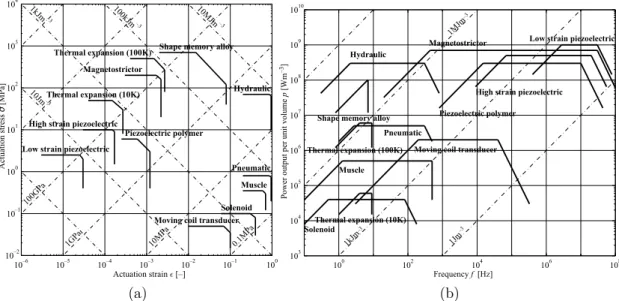
The previous section presents an overview of electroactive materials. The selection of the material the most suitable for a given application is done by comparing the diferent materials. Huber et al. [HFA97] propose a comparison based on graphics. Therefore, it is possible to compare the diferent actuator technologies (including electroactive materials, conventional magnetic actuators and natural muscle) on a same diagram, for instance stress VS strain in Figure 1.9a or power output VS frequency in Figure 1.9b. Depending on the application (static, dynamic, damping, ...) igures of merits are calculated and a new digram representing the materials
10–6 10–5 10–4 10–3 10–2 10–1 100 10–2 10–1 100 101 102 103 104 Actuation strain ² [–] Ac tua ti on st re ss σ [MPa ] 0.1MPa 10MPa 1GPa 100GPa 10MJm 100kJm 1kJm 10Jm –3 –3 –3 –3
Low strain piezoelectric High strain piezoelectric
Piezoelectric polymer Thermal expansion (10K)
Thermal expansion (100K) Magnetostrictor
Shape memory alloy
Moving coil transducer Solenoid Muscle Pneumatic Hydraulic (a) 100 102 104 106 108 103 104 105 106 107 108 109 1010 1MJm 1kJm 1Jm –3 –3 –3 Frequency f [Hz] Powe r out put pe r uni t vol um e p [W m –3]
Low strain piezoelectric
High strain piezoelectric Piezoelectric polymer
Thermal expansion (10K) Thermal expansion (100K)
Magnetostrictor
Shape memory alloy
Moving coil transducer
Solenoid Muscle
Pneumatic Hydraulic
(b)
Figure 1.9: Representation of actuator technologies in stress VS strain diagram (a) and power output VS frequency diagram (b). From Huber et al. [HFA97].
as a function of the igures of merits. By the way, this approach developed by M. F. Ashby is also compatible with passive structure to ind the best material.
A limit clearly announced of the previous comparisons is that the order of magnitudes of mass and volumes does not take auxiliary devices (casing, power supplies, valves/switches, ...) into account. For example magnetostrictive materi-als have a large output power density, but adding the mandatory coils and iron cores to made the actuator spoiled the total power density.
Only few research gives elements on true actuators as it depends on the ap-plication. Generally, applications requiring magnetic ields are much penalized; hydraulic actuators are penalized by the compressor and hydraulic network but the penalty is lower for a large number of hydraulic cylinders connected to one network.
Finally, this comparison does not imply the choice of one material for a given application. The disadvantages of one material can be compensated by another. For instance, the low frequency response of SMA and the limited deformations of piezo-ceramics has been compensated by the use of both these materials, by Pankonien et al. [PFI15]. Their synergistic smart morphing aileron includes a SMA actuated hinge plus a bending trailing edge. The piezo-actuator is used for quick response whereas the SMA are used for large deformations. Another example of material combination is applied to vibration energy harvesting to supply small autonomous electronic devices. Dielectric polymers can eiciently harvest mechan-ical energy with high strain but requires a power supply, whereas piezo-ceramic harvesters are autonomous but brittle. Cornogolub et al. [CCP16] associated both the two materials in one harvesting system: a irst “piezo-harvester” generates the require electric source for the dielectric polymer harvester. The coupling topology has been optimized and a prototype is realized for experimental validation.
1.4.2 Actuators for morphing
1.4.2.1 Conventional aircraft actuators
The two following paragraphs present conventional aircraft actuator technologies to highlight the industrial philosophy on this topic. Firstly manual, the increase of aircraft size requires more force on control surfaces. Beginning with hydraulic assistance actuators, recent aircrafts are now ̀“ly-by-wire”, an electronic interface exchange informations between the pilot and the actuators. Conventional aircraft actuators consist in cylinder like actuators. Two ball joint anchors link the movable surface and the wing to the cylinder rod and case. The distance between the
Figure 1.10: Picture of an Electro-Hydrostatic Actuator for A380 aileron, 2007 Hydraulic Actuators rely on a global hydraulic system, powered by the aircraft engines. Despite its high reliability, the complex and wide hydraulic network is heavy and costly to maintain. A next approach is the use of a local hydraulic circuit, power by an electric pump – Figure 1.10 presents a A380 aileron’s Electro-Hydrostatic Actuator. The Electro-Electro-Hydrostatic Actuators are based on this prin-ciple and are compatible with a redundant fully hydraulic system. One main advantage of hydraulics are the behavior during failure cases. Indeed, in case of actuator failure, the movable surface goes to neutral position due to aerodynamic loading and the moving oil in the cylinder provides enough damping to prevent any luid-structure dynamic instability. The most recent actuators are named Electro-Mechanical Actuators. They use no hydraulic power. These components are generally composed of a high speed rotating electric motor, a dropbox and a ball screw to transform the rotation to the translation of the cylinder rod. The ad-vantages are the reduced mass and easier maintenance, but thermal management has to be seriously dealt. The main drawback is that the failure cases are very diferent from the hydraulic actuators. A mechanical failure can lock the control surface at a given position, which is not tolerable for critical functions. The im-plementation of Electro-Mechanical Actuators everywhere on an aircraft requires a system approach and to re-deine functions.
1.4.2.2 Smart material actuators
The following paragraphs focus on shape memory alloy and piezoelectric actuators.
Shape Memory Alloy (SMA) actuators
Methods for designing SMA actuators have been studied. W. Kim [Kim16] de-tails a design framework for SMA wire actuators. The wires can be embedded in
composite structures. For instance, bending beams with embedded SMA wires are detailed by Ma et al. [MSL04].
The use of designed SMA actuators require control. Despites their non lineari-ties, the control of SMA actuators is mastered. Based on state space theory, the control of a SMA wire at contant tension with perturbation is assessed bu Jayen-der et al. [Jay+08]. Control of a agonist/antagonist actuator with several crossing SMA stages has been achieved by Grant et al. [GH97]. A feedback controller with diferent states is used. Additionally, feedback control based on artiicial intelli-gence has also been investigated. Song et al. [SCB03] propose a neural network controller for SMA wire with counter spring.
Concerning SMA actuator, the research projects SAMPSON or the lap actua-tor of Boeing described in 1.2.2.3 are good examples.
To illustrate other industry application, General Motors developed a SMA ac-tuator commercialized on the Corvette 20143, [Jan+14]. This actuator consists in
silently opening an event to ease the door closing.
Piezoelectric actuators
The main applications of piezoelectric materials are piezoelectric ceramic stacks (piezo-stacks) and Macro Fiber Composite (MFC). The MFC are composite mate-rials embedded LZT iber with electrode within an epoxy structure.
One application of piezoelectric materials is electroactive lubricant. This is performed by introducing vibrations at the contacts between two mechanical parts. This can be used to realize high torque/low velocity motors based on quasi-static motion of piezo-stack actuators, as done by Rouchon et al. [Rou+13].
Piezoelectric materials have limited actuation strain. One way to increase the piezo-actuator stroke is the use of non-linear structural instability like buckling. Neal et al. [NA09] assembled two piezo-stacks and a spring to control bucking of a structure. Such control can also be more integrated: Giddings et al. [Gid+11] work on bistable plates made of carbon iber composite with MFC embedded that allow for an active control of the shape. Such plates exhibit two diferent stable shapes, the actuation of embedded MFC is used to switch from a shape to another.
Next section focuses on these actuators’ potential for aircraft morphing.
1.5 Smart and active structures for
morphing aircrafts
One reason justifying why there are so many diferent research about morphing structures is the following paradox: the structure has to be lexible enough to
(a) (b)
Figure 1.11: (a) MFC actuated wing from Debiasi et al. [Deb+13]. (b) morphing skin from Bubert et al. [Bub+10].
be deformed, but stif enough to carry the aerodynamic forces without being de-formed.
Structures and skins
Nowadays, diferent propositions solve this paradox. A irst bio-inspired example is the ish bone active camber morphing concept, created by Woods et al. [WBF14]. This concept relies on a bending beam spine with stringers. An elastic skin is taut over this structure and the whole is controlled by a servomotor driving tendons attached on the spine.
Another approach is the use of a bending upper skin with lexible truss elements inside the wing. Wu et al. [Wu+17] propose a coniguration where the lower skin is cut and the diferent parts glide one upon the others. The whole is plane to be actuated by linear ultrasonic motors (based on piezoelectric materials). But the realized prototype was actuated by servomotor pulling wires linked to the truss elements.
Ramrakhyani et al. [Ram+05] propose a morphing structure based on tendons embedded in a compliant cellular truss. This work based on optimization does not propose skin solution to realize a demonstrator.
Michael X. Meyer from Airbus4 says that morphing most important limitation
is skin technologies. Indeed, even if the internal structure can be deformed whilst carrying the forces, the skin which provides the interface with the airlow has also to exhibit the same behavior. Towards the design of a skin with low elongation resistance, but with high out-of-plan stifness and zero poisson ratio, Bubert et al. [Bub+10] proposed an anisotropic structure with an elastomer cover. The concept is visible in Figure 1.11b. This skin can be easily stretched but carry the forces with limited bending.
4Keynote at 52nb International Conference on Applied Aerodynamics, Lyon, France, 2017
Structures with SMA actuators
What about adding SMA actuators in an Airbus A380 wing to control the twist ? G. Duval [Duv05] worked on this question and answer that this can be achieved by approximately adding 50kg of SMA to the existent structures. This amount can be optimized if the structure can be adapted. Concerning more academic research, Rediniotis et al. [Red+02] have worked on a biomimetic hydrofoil. By assembling SMA actuated hinges in series, they have studied the swimming of their robot.
The idea of SMA morphing wings have raised a lot of studies regarding low scale and low velocity wings with a SMA actuated camber control. Diferent or similar topologies are used. Papers resulting from these studies states an innovative control system that improve aerodynamics of the wing. A few examples follows: [KBR14], [ESW03], [Mus01] or [SLY08].
Structures with piezoelectric actuators
The small deformations provided by the piezoelectric materials do not restrict them for reduced scale applications. Janker et al. [Jan+06] draw a review of piezoelectric actuator applications for aircraft. For instance, ampliied piezo-stack actuator allows for controlling an aileron on rotative wings of rotorcraft. The aileron is actuated at the rotation frequency (≈ 50Hz). Another example is piezoelectric active dampers for passenger comfort or protecting sensitive payloads.
Piezoelectric benders have been investigated by Li et al. [Li+15] to passively control the lutter instability. Their work has been based on numerical simulations.
Micro Air Vehicles (MAVs) with piezoelectric actuators have been designed and build. LaCroix et al. [LI14] have developed a twist control thanks to MFC. This allows to control the roll without conventional aileron. Another MAV – developed by Ohanian [Oha+12] – has been updated from conventional ailerons actuated by servomotor to lexible wings actuated by MFC. It has been shown that the aerodynamic performance and controllability are increased but actuators are 70% heavier in the worst design case.
Another interesting application of the MFC is proposed by Debiasi et al. [Deb+13]. MFC glued on both pressure and suction sides of a small airfoil, as visible in Figure 1.11a. The actuation cause a change in the shape with a good dynamic. Perfor-mance improvements have been validated by wind tunnel experiments.
1.6 Conclusion and originality of the
proposed work
This chapter draws a non exhaustive state of the art regarding electroactive mor-phing and associated ields: ornithology, light physics, industrial development around morphing topic, luid mechanics and turbulence, low control, electroactive materials. It appears that small scale electroactive morphing is well represented. Also low control (without morphing) is a current research topic. Academic re-search aims are diferent from industrial requirements. System approaches that attempt to solve structural, actuation and aerodynamic issues are rare. Only a few research focuses on morphing application at realistic scales regarding commer-cial passenger aircraft.
The proposed multidisciplinary approach of this manuscript therefore seems original. It consists in the development of a complete wing that investigates elec-troactive morphing through turbulence control. Discussions with Airbus results in industrial speciications used to design a true scale electroactive morphing wing part.
Furthermore, the European research project SMS5 “Smart Morphing and
Sens-ing for aeronautical conigurations”, started on 2017/05/01. It focuses hybrid morphing efects developed in the present manuscript. The present state of the art has presented the background of this project.
5http://smartwing.org/SMS
![Figure 1.4: Picture of the SARISTU wing prototype from [Nag+16]. It embeds the diferent demonstrators of the assessed technologies of the project.](https://thumb-eu.123doks.com/thumbv2/123doknet/3063864.86461/20.892.163.785.150.619/figure-picture-saristu-prototype-diferent-demonstrators-assessed-technologies.webp)
![Figure 1.5: Picture of the Gulfstream III SubsoniC Research Aircraft Testbed, with the morphing lap prototype from [Mil+16]](https://thumb-eu.123doks.com/thumbv2/123doknet/3063864.86461/21.892.112.732.149.492/picture-gulfstream-subsonic-research-aircraft-testbed-morphing-prototype.webp)
![Figure 1.6: Reynolds and shape efects on wings and bluf bodies, from Ander- Ander-son [And10]](https://thumb-eu.123doks.com/thumbv2/123doknet/3063864.86461/23.892.106.734.243.925/figure-reynolds-shape-efects-wings-bodies-ander-ander.webp)
![Figure 1.7: Compressibility efects on wings, from Anderson [And10].](https://thumb-eu.123doks.com/thumbv2/123doknet/3063864.86461/25.892.172.663.149.646/figure-compressibility-efects-wings-anderson-and.webp)