HAL Id: tel-01314260
http://hal.in2p3.fr/tel-01314260
Submitted on 11 May 2016HAL is a multi-disciplinary open access archive for the deposit and dissemination of sci-entific research documents, whether they are pub-lished or not. The documents may come from teaching and research institutions in France or abroad, or from public or private research centers.
L’archive ouverte pluridisciplinaire HAL, est destinée au dépôt et à la diffusion de documents scientifiques de niveau recherche, publiés ou non, émanant des établissements d’enseignement et de recherche français ou étrangers, des laboratoires publics ou privés.
Laser Ionization
Jose Luis Henares Gonzalez
To cite this version:
Jose Luis Henares Gonzalez. Study of Condensable Ion Production by Resonant Laser Ionization. Accelerator Physics [physics.acc-ph]. Normandie Université, 2016. English. �tel-01314260�
“Every act of perception is, to some degree, an act of creation and every act of memory is, to some degree, an act of imagination.” Gerald M. Edelman (Physiology Nobel Prize)
Acknowledgement
In the next lines I would like to thank the people that contributed to this fascinating adventure. It was a great pleasure to work with people passionated by their jobs. All people that appear here provided me experience, training and a different way of thinking.
First, I would like to thank the Marie-Curie network for this incredible opportunity of train-ing and personal growtrain-ing. Special thanks to Carsten and Rob great coordinators and fantastic people to follow closely. Also many thanks to Magda and the rest of LA3NET staff. Thank
you all fellows (Andreas, Alexandra, Irene, Luca, Mateusz, Andrii, Tom, Cheng, Jurjen, Lara, Thomas, Stanimir, Jackob, Pegnan, Kamil, Rui, Mathieu and Yelong) for the nice scientific and personal exchanges all around the world. Good luck and keep in touch!
I must express my gratitude to my supervisors Nathalie and Marek, and for the rest of the GISELE team (Renan, Benoit, Marica and Samuel) for the training, the discussions and the time spent to obtain the results for the thesis. Also many thanks to the people of GANIL which helped me with the different problems that appeared during the thesis, with thanks to Jean Luc for the low energy beam profiler, Jean Claude for the nice discussions, C´ecile for the thermal analysis and special thanks to Beyhan who was the fundamental key to develop the acquisition system and provided interesting discussions to the thesis.
I greatly appreciate the opportunity of working together with other laboratories. So I would like to give thanks to Klaus and LARISSA team (kind regards to Tobias, Pascal and Fabian) and Jens and TRILIS team (thanks Andrea and Ruohong for welcoming me, you are very nice!) for the opportunity to participate in experiments, and for the discussions and support during the thesis and the back-feeding of corrections for the manuscript.
Special thanks to Florent and Marija thesis-mates and good friends since the first day at GANIL. Carme and Dennis, thank you for your discussions, comments, coffees and friend-ship. And thanks to Haifa, Guillaume S., Mathieu, Pierre, Guillaume B., Coralie, Luca, Arek, Quentin, Hongliang, Marine, Bartholome, Benoit, Aldric and the rest of PhD students and post-doc, you were the best company one can have and I wish you the best for your careers.
Finally, I give thanks to my parents and family for the support during the dissertation defense. Thanks to Claire, Felipe M., Marie, Felipe Z., Luc´ıa and Etienne for your friendship and second during these years. And finally special thanks to Esther for your continued support, happiness and encouragement, during good and hard times. Thank you for the thesis drawings, schemes and discussions. It’s because of you that I succeed in doing this thesis. Your eyes shine like the stars.
This project has received funding from the European Union’s Seventh Framework Pro-gramme for research, technological development and demonstration under grant agreement no 289191.
Contents
Preface 13
Context . . . 13
General objective of the thesis . . . 14
1 Radioactive-ion beams 19 1.1 Introduction . . . 19
1.2 Production of radioactive-ion beams . . . 20
1.2.1 In-Flight method . . . 21
1.2.2 ISOL method . . . 22
1.3 Ionization methods . . . 23
1.3.1 Surface Ionization . . . 23
1.3.2 Forced Electron Beam Induced Arc Discharge (FEBIAD) . . . 24
1.3.3 Electron Cyclotron Resonance (ECR) . . . 25
1.3.4 Laser Resonance Ionization . . . 26
1.4 GANIL-SPIRAL2 radioactive ion beam facility . . . 27
1.4.1 GANIL . . . 27
1.4.2 SPIRAL2 . . . 27
2 Resonant Ionization Laser Ion Source 31 2.1 Resonant photo-excitation process . . . 31
2.2 RILIS requirements . . . 33
2.2.1 Laser specifications for the RILIS technique . . . 35
2.2.2 Available laser systems for the RILIS technique . . . 41
2.3 Laser-atom interaction devices . . . 45
2.3.1 Hot cavity . . . 45
2.3.2 Gas cell . . . 47
2.3.3 Comparison of interaction devices . . . 48
2.4 Contaminant reduction and ion beam purification . . . 49
2.4.1 Selectivity . . . 49
2.4.2 Low work function materials . . . 52
2.5 Origins and evolution of the RILIS technique . . . 59
3 GISELE laser system 65 3.1 Off-line test bench . . . 65
3.2 Laser system setup . . . 66
3.2.1 Nd:YAG pump laser . . . 67
3.2.2 Ti:sapphire lasers . . . 68
3.2.3 High harmonic frequency generation . . . 71
3.2.4 Laser beam transport to the ion source . . . 72
3.2.5 Laser beam diagnosis . . . 74
3.2.6 Laser monitoring and control system . . . 75
3.3 Reference cell . . . 76
3.4 Resonant photo-excitation and ionization schemes . . . 77
3.4.1 Ionization schemes research . . . 77
3.4.2 Resonance transition saturation . . . 79
3.4.3 Requested elements . . . 80
3.5 Zinc ionization schemes . . . 80
3.5.1 Physico-chemical properties of zinc . . . 80
3.5.2 Atomic transitions research . . . 81
3.5.3 Discussion . . . 85
3.5.4 Conclusion . . . 90
3.6 Tin ionization schemes . . . 91
3.6.1 Physico-chemical properties of tin . . . 91
3.6.2 Possible ionization schemes . . . 92
3.6.3 Comparison and discussion . . . 94
3.6.4 Conclusion . . . 96
4 Ion source test bench 99 4.1 Ion source . . . 100
4.1.1 Interaction device development . . . 100
4.1.2 Electric field configurations . . . 102
4.1.3 Low electron emission work function materials . . . 102
4.1.4 Ion source temperature calibration . . . 103
4.1.5 Interaction device thermo-electric study . . . 107
4.2 Ion extraction . . . 108
4.3 Magnetic sector field mass spectrometer . . . 109
4.4.1 Faraday cup . . . 109
4.4.2 Low intensity ion beam profiler . . . 110
4.5 Test bench monitoring and control system . . . 111
4.6 Extraction system optimization . . . 112
4.6.1 Simulation description . . . 113
4.6.2 First electrode distance optimization . . . 116
4.6.3 Two step extraction optimization . . . 117
4.6.4 Comparison with measurements . . . 120
5 Ion source geometry study 123 5.1 Geometry comparison as a function of the efficiency . . . 123
5.1.1 Efficiency measurement . . . 123
5.1.2 Sample preparation . . . 127
5.1.3 Background reduction for efficiency measurements . . . 130
5.1.4 Experiment requirements . . . 133
5.1.5 Efficiency results for different LISBET geometries . . . 133
5.1.6 Efficiency discussion . . . 140
5.1.7 Optimum diameter simulation . . . 144
5.2 Geometry comparison as a function of the emittance . . . 145
5.2.1 General definition of the emittance . . . 145
5.2.2 Emittance results for different LISBET geometries . . . 149
5.2.3 Emittance discussion . . . 152
5.3 Ion time structure study . . . 154
5.3.1 Acquisition system . . . 154
5.3.2 RILIS time profile structures . . . 158
5.3.3 Simulations . . . 162
5.3.4 Time structure discussion . . . 163
5.4 Energy distribution scans . . . 166
5.4.1 Method description . . . 166
5.4.2 Energy distribution for the LISBET-D7L35 geometry . . . 167
5.4.3 Energy scan discussion . . . 171
5.5 Research for the improvement of the selectivity . . . 174
5.5.1 Element of study . . . 174
5.5.2 Electric field potential comparison . . . 175
5.5.3 Effect of ZrC as contamination reduction agent . . . 179
5.5.4 Study of the contamination reduction due to the ionizer diameter . . . . 179
5.5.5 Contamination reduction discussion . . . 180
5.5.6 RILIS ion production in the LISBET device with ZrC . . . 181
Outlook . . . 189
A Laser fundamentals 203
B Work function measurement 207
Bibliography 210
List of Figures
1.1 Representation of the atomic nuclei chart. . . 20
1.2 Scheme of radioactive-ion beam production by in-flight method. . . 21
1.3 Scheme of radioactive-ion beam production by the ISOL method. . . 22
1.4 Positive surface ionization process. . . 24
1.5 Ionization by electron impact (FEBIAD ionization). . . 24
1.6 Diagram of the Electron Cyclotron Resonance (ECR) ionization technique. . . . 26
1.7 Diagram of the multi-step resonant photo-excitation process. . . 27
1.8 Floor plan of the existing accelerator facility at GANIL and the planned SPIRAL2. 28 1.9 Scheme of radioactive-ion beam production by the ISOL method for SPIRAL2-GANIL. . . 29
1.10 Target module front-end picture of the Uranium Carbide target furnace and ion source for SPIRAL2 Phase-2. . . 30
2.1 Ionization potential for several chemical elements. . . 32
2.2 Alternative ways to reach the ionization potential for the final step. . . 33
2.3 Resonant Ionization Laser Ion Source diagram. . . 34
2.4 Schematic explanation of the RILIS Z-selectivity. . . 35
2.5 Diagram of Q-switch mechanism. . . 36
2.6 Two ways of wavelength selection: The etalon filter and the diffraction grating. . 39
2.7 Jablonski diagram for a dye laser molecule. . . 41
2.8 Jablonski diagram for a titanium:sapphire crystal. . . 43
2.9 Absorption and fluorescence emission spectrum of a ti:sa laser. . . 43
2.10 Accessible wavelengths for ti:sa and dye laser systems. . . 44
2.11 Scheme of one of the first designs of the hot cavity concept. . . 46
2.12 Scheme of the dual chamber laser ion source gas cell. . . 48
2.13 Example of the dependence of the production on the mass of produced isotope. . 50
2.14 Scheme of the ISOLDE target Ta-174. . . 57
2.15 3D-CAD sketch of the LIST device. . . 58
2.16 Spectroscopy experiment carried out by ISAN, LNPI, COMPLIS-ISOLDE and Mainz University in 1982 . . . 59
2.18 Schematic drawing of the target and hot cavity ionizer setup at the ISOLDE-3
mass separator. . . 61
2.19 The former scheme of the laser ion source system at ISOLDE. . . 62
2.20 Schematic drawing of one of first LIST prototypes. . . 63
2.21 Existing resonant laser ion sources using hot-cavity devices at radioactive-ion beam facilities. . . 64
3.1 GISELE laser system and the off-line test bench . . . 65
3.2 GISELE laser system setup. . . 66
3.3 Pump laser transport towards the laser cavities. . . 67
3.4 Ti:sapphire resonator with all of the opto-mechanics parts developed by TRILIS-TRIUMF . . . 68
3.5 Laser wavelength selection for different mirror-set. . . 69
3.6 Pulse synchronization by Pockels cell. . . 70
3.7 Frequency triple conversion unit. . . 71
3.8 Laser transport from the laser cavity towards the ion source. . . 72
3.9 Diagram of Galileo telescope. . . 73
3.10 The reference point is installed in the laser room. . . 74
3.11 Images recorded by the CCD camera connected to the telescope. . . 75
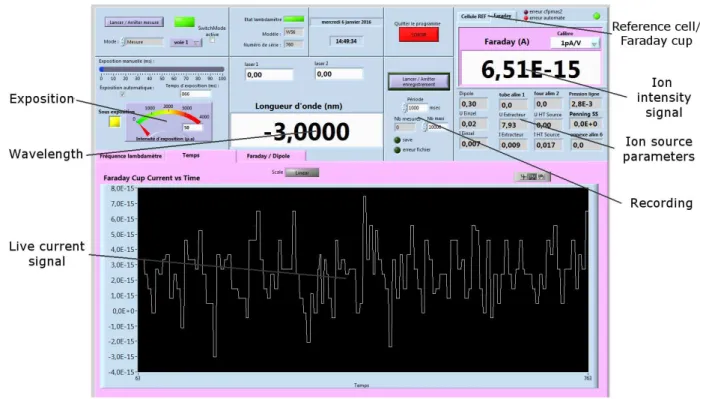
3.12 Command control front end. . . 76
3.13 Reference cell diagram. . . 77
3.14 Saturation curves examples. . . 80
3.15 Zinc vapor pressure calculation. . . 81
3.16 Three-steps ionization scheme used for Zn at ISOLDE. . . 82
3.17 Possible ionization scheme options for Zn. . . 85
3.18 Zn Auto-Ionizing States (AIS) transitions scanned in a two-step ionization scheme. 86 3.19 Second Excited State scans in a three-step ionization scheme. . . 87
3.20 Saturation measurement for Zn three-step schemes. . . 89
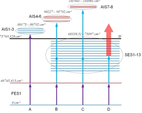
3.21 First Excitation Step (FES1) and Second Excitation Step (SES1) transitions scans for Zn. . . 90
3.22 Ionization scheme chosen for resonant laser ionization of Zn at GANIL. . . 91
3.23 Tin vapor pressure calculation. . . 92
3.24 Ionization schemes for Sn. . . 93
3.25 First Excitation State comparison for Sn three-step ionization schemes. . . 95
3.26 First Excited State, Second Excited State and Auto-Ionization State transition scans for C ionization scheme and Auto-Ionization State for D ionization scheme. 95 3.27 Ionization scheme chosen for resonant laser ionization of Sn at GANIL. . . 96
3.28 Saturation measurement using the Sn three-step scheme. . . 97
4.1 Ion source test bench. . . 99
4.2 LISBET ion source. . . 101
4.3 Electric scheme of LISBET. . . 101
4.4 The possible configurations for the electric current in the ion source. . . 102
4.5 Insertion of ZrC tubes into the 7 mm diameter ionizer tube and schematic of the final assembly. . . 103
4.6 Calibration measurement for LISBET ion source with 7 mm ionizer diameter. . 104
4.7 Calibration measurement for LISBET ion source with 3 mm diameter. . . 104
4.8 Calibration measurement with the ZrC inserted into LISBET ion source with 7 mm diameter. . . 105
4.9 Comparison of the voltage drop measured in the ion source terminal connection 105 4.10 Thermal simulation of LISBET-D7L35 with mutual radiation configuration. . . . 107
4.11 Thermo-electric calculation of LISBET-D7L35 with the electric current arriving from the elbow tab. . . 108
4.12 Extraction system motorized elements and once mounted in the off-line test bench.108 4.13 Low intensity ion beam profiler. . . 110
4.14 Example of profiler measurements. . . 111
4.15 Command control front end. . . 112
4.16 Picture of the equi-potential lines of the electric voltage generated by the resistive heating. . . 113
4.17 SIMION simulation geometries used to optimize the ion beam generation. . . 114
4.18 The ionizer was divided into several parts to simulate the voltage drop. . . 114
4.19 Maxwell-Boltzmann velocity distribution of Sn ions at different temperatures. . 115
4.20 Simulation comparison for 15 mm, 30 mm, 45 mm, and 60 mm distances with one extraction electrode. . . 118
4.21 Simulation comparison for the distances 15 mm, 30 mm, 45 mm, and 60 mm with two extraction electrodes. . . 119
4.22 Sn ion current intensities generated at several distances of the first extraction electrode. . . 121
4.23 Optimized simulation parameters . . . 121
4.24 Comparison between the simulated ion beam profile and the profile measured with the low intensity profiler. . . 122
5.1 Efficiency measurement example. . . 124
5.2 Example of Sn background signal at temperatures higher than 2000 K. . . 128
5.3 Ion current measured without sample in several consecutive experiments. . . 130
5.7 Saturation measurements performed with the Sn three-step scheme for two ion
source geometries. . . 134
5.8 Ion current accumulated with LISBET-D7L35, LISBET-D7L60, LISBET-D3L35 and LISBET-D3L60. . . 137
5.9 Simulation examples of the ionizer and the extraction electrodes . . . 139
5.10 Electric field distribution of the ion source and the extraction electrode system for LISBET-D7L60 geometry. . . 140
5.11 Efficiencies of different ion source geometries. . . 141
5.12 Schematic drawing of the hot-cavity ion source at Oak Ridge. . . 142
5.13 Definition of position and velocity for a particle propagating through an axis. . . 145
5.14 Emittance characterization by the slit-grid method. . . 146
5.15 Emittance figure example. . . 148
5.16 Rms emittances 2σ measured. . . 149
5.17 Emittance simulations for different LISBET configurations. . . 151
5.18 Emittance measurement evolution as a function of the working temperature. . . 152
5.19 Diagram of the electronic chain and data acquisition system using a Faraday cup.154 5.20 Diagram of the electronics chain and data acquisition using a low intensity ion beam profiler. . . 156
5.21 Diagram of signal time line to determine the time-of-flight of ions. . . 157
5.22 Calibration of the acquisition system. . . 157
5.23 Time profile structure measurement diagram example. . . 158
5.24 Ion beam simulation where the starting position of the ions in the ionizer was compared to their time of flight. . . 159
5.25 Time structure measurements for D7L35, D7L60, LISBET-D3L35 and LISBET-D3L60. . . 160
5.26 Ratios between the ions in the main broad peak divided by the total number of ions as a function of the temperature. . . 162
5.27 Time structure simulation for the different LISBET configurations at 2000 K. . . 163
5.28 Simulation comparing the initial position of ions. . . 164
5.29 Diagram of the ion beam energy scan. . . 166
5.30 Calibration of the kinetic energy centroid as a function of the position after the dipole. . . 167
5.31 Time profile measurement of 124Sn (above) and the energy distribution measured.168 5.32 Energy distribution reversing the electric field potential in the ionizer. . . 168
5.34 Ion beam simulation where the starting position of the ions in the ionizer was
compared to their time of flight. . . 170
5.35 Simulated energy spread for each LISBET configuration. . . 171
5.36 Mass spectrum of Sn with the generated isotopes. . . 173
5.37 The possible configurations for the electric current in the ion source. . . 176
5.38 Option A: electric field towards the extraction system (forwards). . . 177
5.39 Option B: Electric field potential towards the target (backwards). . . 177
5.40 Option C: Electric field potential backwards for the ionization tube and forwards for the transfer tube. . . 178
5.41 Option D: Electric field potential forwards for the ionization tube and backwards for the transfer tube. . . 178
5.42 Option D+ZrC: Electric field potential set in the same conditions as D, but the ZrC ceramics were inserted into the ionizer. . . 179
5.43 Ion current accumulated with LISBET-D3L35 + ZrC for 124Sn efficiency mea-surement. . . 181
5.44 Example of an imperfect fit of the ZrC rods into the 7 mm diameter ionizer. . . 182
5.45 Rms emittance 2σ of LISBET-D7L35 + ZrC. . . 183
A.1 Diagram of the stimulated emission process. . . 203
A.2 Schematic explaining the operation of a laser system. . . 205
B.1 Work function calculation example by the measurement of the surface ionization degree of Rb. The logarithm of the ionization degree as a function of the inverse of the temperature. . . 209
Tables
2.1 Comparative table of titanium:sapphire and dye laser options. . . 44
2.2 Comparative table between hot cavity and gas cell interaction devices. . . 48
2.3 Work function and properties of pure refractory metals. . . 53
2.4 Work function and properties for cabide-based ceramics. . . 54
2.5 Work function and properties of boride-based ceramics. . . 55
2.6 Work function and properties for oxide-based ceramics. . . 56
2.7 Selectivity tests with several ion source materials. . . 56
3.1 Transitions to the First Excited States of Zn. . . 82
3.2 Transitions from FES1 to Second Excited States of Zn. . . 83
3.3 Possible transitions to Auto-Ionization States of Zn. . . 84
3.4 Transitions from FES1 to the possible AIS for the Zn two-step ionization schemes. 86 3.5 Zn three-step scheme combinations between Second Excited States (SES) and Auto-ionization States (AIS). . . 88
3.6 Tin three-step resonant photo-excitation schemes. . . 94
3.7 Leuven two-step scheme for Sn. . . 94
4.1 Comparative table of each laser ion source body used at GANIL. . . 101
4.2 Currents and voltages measured for different ion sources at 2000 K. . . 106
4.3 Faraday cup error measured for a chosen caliber set. . . 110
4.4 Summary of the simulations performed with one extraction electrode at 19 kV. . 116
4.5 Optimum electric potential values found for several distances. . . 117
4.6 Summary of the simulations performed with two extraction electrodes. . . 120
5.1 Typical contamination elements that can be found in a commercial titanium (Ti) and tantalum (Ta). . . 129
5.2 Samples used to produce an atomic vapor inside the hot-cavity. . . 129
5.3 Efficiency results for the studied LISBET configurations. . . 135
5.4 Efficiency results for the studied LISBET configurations. (continuation). . . 136
5.5 Propagation efficiencies simulated with SIMION. . . 138
5.6 Extraction potential depth calculated from SIMION simulations. . . 140
5.9 Simulations performed with different ionizer diameters. . . 144
5.10 Overall emittances for different ion source geometries measured at the low in-tensity ion beam profiler. . . 152
5.11 Summary of the measured main peak positions at 1900 K for different LISBET configurations. . . 161
5.12 Representative surface ionization elements. . . 174
5.13 Reduction factors measured for the different electric potential directions. . . 181
5.14 Efficiency results for LISBET-D7L35 + ZrC. . . 182
5.15 Comparison between the ion productions obtained with 3 mm diameter and 7 mm diameter ionizers. . . 183
B.1 Estimated values of the ionization efficiency to calculate the work function value of a material. . . 209
Preface
Context
On-line isotope separators are of great interest in the generation of high intensity pure short-lived radioactive ion beams (RIBs). For that reason, different ion source techniques are under development worldwide to provide pure RIBs. During the decade of 1980 a technique, called Resonant Ionization Laser Ion Source (RILIS), based on the step-wise resonant photo-excitation and ionization of atoms of interest, was developed for frontier research in several domains. The RILIS is a selective ion source which provides high ion beam intensities, a low ratio of contaminants and it gives access to exotic and rare nuclei at on-line nuclear facilities like ISOLDE at CERN (Geneva, Switzerland) [1] or ISAC at TRIUMF (Vancouver, Canada) [2].
Nowadays, the Resonant Ionization Laser Ion Source (RILIS) technology has emerged as an important tool for several applications including Radioactive Ion Beam generation (RIB) [3, 4, 5], atomic spectroscopy [6, 7, 8] or ultra-trace analysis [9, 10]. RILIS is extensively used worldwide and the number of accessible elements increases each year. The main advantages are: a reduced production of isobaric impurities, an inherent Z-selectivity, a relatively high efficiency and a pulsed structure of the ion beam. All of these permit to use the RILIS as a universal and reliable ion source. The RILIS technique requires detailed laser spectroscopy information on atomic spectra and excitation schemes of all elements of interest. This allowed the use of RILIS as a tool for spectroscopy development, at the same time this information provided the feedback needed to the technique breakthrough. Up to now more than 51 elements are available with the RILIS [11, 12]. Nevertheless the probability of non-selective surface ionization of unwanted isobar contaminants must be minimized, in the case of the RILIS using a hot-cavity. In conclusion, the recent development of the RILIS concerns ionization efficiency, emittance and, isotopic and isomeric selectivity.
The objective of the present work is the study and implementation of a Resonant Ionization Laser Ion Source in an off-line test bench at GANIL (Caen, France). The test bench was first successfully adapted and optimized for the RILIS from an ECR (Electron Cyclotron Resonance) test bench (chapters 3and 4). The optimization included simulations and experiences focused on the search of the optimum extraction and transport parameters. In addition, the RILIS test bench was used to develop a low energy beam profiler that will be installed for SPIRAL2. This device was extensively used to characterize the ion beam.
Tin and zinc ion beams were produced by a RILIS and an experimental research was per-formed for both elements to find alternative and possibly more efficient resonant atomic tran-sition schemes to the already known ones. The study included spectroscopy measurements and bibliographical research (section 3.4).
The influence of the RILIS ion source geometry to the ion beam characteristics was not studied in full depth yet. In this work a study was performed with different ion source shapes, in order to improve the RILIS performance. Efficiency, emittance and the arrival time of the generated ions were measured and compared for different ion source settings (chapter 5). In addition, the electric field generated by the resistive heating can have impact on the ion extraction by a small potential drop and corresponding acceleration in the ion source tubes, thus it may modify the ionization efficiency for laser ionized atoms.
The RILIS technique is known for its selectivity and ability to produce pure ion beams. In the case of using a hot-cavity to perform the laser-atom interaction, the production of alkali contamination due to surface ionization at high temperatures is still an unsolved problem. For this reason, two contamination reduction methods were studied. One concerning the control of the electric field generated by resistive heating, and the second by the study of low work function materials in order to reduce the surface ionization of alkali contaminants (section5.5). Finally, a new technique to measure the energy distribution of the ion beam was developed, in order to understand the underlying physics concerning the ionization process inside the ion source. This technique may resolve some of the open and unexplained ion source behaviours. First measurements and interpretation are provided (section 5.4).
Pr´
eface
Contexte
Le principal int´erˆet des s´eparateurs d’isotopes en-ligne est la g´en´eration de faisceaux d’ions radioactifs de forte intensit´e et de courte dur´ee de vie (RIB en acronyme anglais). Pour cette raison, diff´erentes techniques de production d’ions sont en cours de d´eveloppement dans le monde entier pour fournir des faisceaux d’ions radioactifs de grande puret´e. Au cours de la d´ecennie de 1980, une technique appel´ee source d’ions par ionisation laser r´esonante (RILIS en acronyme anglais) a ´et´e d´evelopp´ee pour la recherche d’avant-garde dans plusieurs domaines. RILIS est bas´ee sur la photo-excitation r´esonante par ´etapes successives des atomes d’int´erˆet. Il est une source d’ions s´elective qui fournit des intensit´es ´elev´ees de faisceau avec un faible taux de contaminants, ce que permet d’acc´eder `a de noyaux exotiques aupr`es d’installations nucl´eaires en-ligne comme ISOLDE au CERN (Gen`eve, Suisse) [1] ou ISAC `a TRIUMF (Vancouver, Canada) [2].
De nos jours, la technique de source d’ions par ionisation laser r´esonante (RILIS) a ´emerg´e comme un outil tr`es important pour diff´erentes applications: la production de faisceaux radioac-tifs [3,4, 5], la spectroscopie atomique [6, 7, 8] ou l’analyse de ultra-traces [9,10]. Cette tech-nique est largement utilis´ee dans le monde entier et le nombre d’´el´ements accessibles augmente chaque ann´ee. Les principaux avantages sont: une r´eduction de la production d’impuret´es iso-bariques, une s´electivit´e intrins`eque en Z, une efficacit´e ´elev´ee et une structure puls´ee du faisceau d’ions. Tous ces ´el´ements permettent de l’utiliser en tant que source d’ions universelle et fiable. En outre, la technique n´ecessite des informations d´etaill´ees sur les spectres atomiques et les sch´emas d’excitation des ´el´ements d’int´erˆet. Cela a permis l’utilisation comme un outil pour le d´eveloppement de la spectroscopie, dont les informations contribuent `a ameliorer la technique. Jusqu’`a pr´esent, plus de 51 ´el´ements peuvent ˆetre produits par la m´ethode RILIS [11, 12]. N´eanmoins, l’ionisation de surface non s´elective des contaminants isobariques doit ˆetre r´eduite au minimum dans le cas d’une RILIS avec cavit´e chaude. En conclusion, le d´eveloppement de RILIS concerne l’efficacit´e d’ionisation, l’emittance et la s´electivit´e, isotopique et isom`erique.
L’objectif de ce travail est l’´etude et l’implantation d’une source d’ions par ionisation laser r´esonante (RILIS) sur un banc de test hors-ligne au GANIL (Caen, France). Le banc de test a ´et´e adapt´e et optimis´e avec succ`es pour RILIS `a partir d’un banc de test pour source d’ions ECR (Electron Cyclotron Resonance) (chapitres3et4). L’optimisation a consist´e en des simulations et des exp´eriences pour trouver les param`etres optimaux d’extraction et transport. De plus, le banc de test RILIS a ´et´e utilis´e pour d´evelopper un profileur de faible intensit´e qui sera install´e dans SPIRAL2. Ce dispositif a ´et´e largement utilis´e pour caract´eriser le faisceau d’ions.
Grˆace `a RILIS, des faisceaux d’ions d’´etain et de zinc ont ´et´e produits et une recherche spectroscopique a ´et´e r´ealis´ee sur ces deux ´el´ements pour trouver des sch´emas d’ionisation alter-natifs `a ceux d´ej`a connues. L’´etude comprenait des mesures de spectroscopie et des recherches bibliographiques (section 3.4).
L’influence de la g´eom´etrie de la source d’ions RILIS sur la g´en´eration des faisceaux d’ions n’avait pas encore ´et´e ´etudi´ee en profondeur. Dans ce travail, afin d’am´eliorer le comportement RILIS, une ´etude a ´et´e r´ealis´ee avec diff´erentes g´eom´etries de la source d’ions. L’efficacit´e, l’emittance et temps de vol des ions produits ont ´et´e mesur´es et compar´es pour les diff´erents param`etres de la source (chapitre 5). En outre, L’impact du champ ´electrique, g´en´er´e par le chauffage r´esistif, sur l’extraction des ions dans les tubes de la source a ´et´e ´etudi´e. Ainsi, le champ ´electrique peut modifier l’efficacit´e d’ionisation pour les atomes ionis´es par laser.
La technique RILIS est connue pour sa s´electivit´e et sa capacit´e `a produire des faisceaux d’ions purs. Cependant, dans le cas d’une source d’ions utilisant une cavit´e chaude, la produc-tion de polluants due `a l’ionisaproduc-tion de surface `a haute temp´erature est encore un probl`eme non r´esolu. C’est pourquoi, deux m´ethodes ont ´et´e ´etudi´ees pour r´eduire la g´en´eration de polluants. La premi`ere concerne le contrˆole du champ ´electrique g´en´er´e par chauffage r´esistif, et la seconde l’´etude des mat´eriaux avec un faible travail de sortie afin de r´eduire l’ionisation de surface des contaminants alcalins (section 5.5).
Finalement, une nouvelle technique pour mesurer la distribution en ´energie du faisceau d’ions a ´et´e d´evelopp´ee, afin de comprendre les processus physiques mis en jeu lors de l’ionisation `a l’int´erieur de la source d’ions. Cette technique peut aider `a comprendre certains comporte-ments encore inexpliqu´es. Des mesures pr´eliminaires et leur interpr´etation sont pr´esent´ees (section5.4).
Pr´
ologo
Contexto
El principal inter´es de los separadores de is´otopos en l´ınea es la generaci´on de haces de iones radioactivos de vida corta y alta intensidad (RIB en su acr´onimo ingl´es). Por esa raz´on, diferentes t´ecnicas de producci´on de iones est´an siendo desarrolladas en todo el mundo para proporcionar haces de iones radioactivos de alta pureza. Durante la d´ecada de 1980, una t´ecnica llamada fuente de iones por ionizaci´on resonante l´aser (RILIS en su acr´onimo ingl´es) fue desarrollada para la investigaci´on de vanguardia. RILIS est´a basado en un proceso de foto-excitaci´on resonante por pasos e ionizaci´on posterior de los ´atomos de inter´es. RILIS es una fuente de iones selectiva que proporciona haces de iones de alta intensidad con baja proporci´on de contaminantes, lo que permite el acceso a n´ucleos ex´oticos en instalaciones nucleares en l´ınea como ISOLDE en el CERN (Ginebra, Suiza) [1] o ISAC en TRIUMF (Vancouver, Canad´a) [2]. Hoy en d´ıa, la tecnolog´ıa de la fuente de iones por ionizaci´on resonante l´aser se ha convertido en una herramienta fundamental en varias aplicaciones, tal como la generaci´on de haces de iones radioactivos [3, 4, 5], la espectroscop´ıa at´omica [6, 7, 8] o el an´alisis de ultra-trazas [9, 10]. RILIS es utilizada en todo el mundo y el n´umero de elementos accesibles aumenta cada a˜no. Las principales ventajas son: la reducci´on de la producci´on de impurezas isob´aricas, una inherente selectividad en Z, una eficacia relativamente alta y una estructura pulsada del haz de iones. Todas estas ventajas permiten utilizar RILIS como fuente de iones universal y fiable. La t´ecnica RILIS requiere informaci´on detallada sobre los espectros at´omicos y los esquemas de excitaci´on de los elementos de inter´es. Por ello, RILIS sirve como una herramienta para el desarrollo de la espectroscop´ıa, al mismo tiempo que esta informaci´on proporciona la retroalimentaci´on necesaria para el avance de la t´ecnica. Actualmente, M´as de 51 elementos est´an disponibles mediante esta t´ecnica [11,12]. Sin embargo, la ionizaci´on t´ermica no selectiva de los contaminantes isob´aricos debe minimizarse en el caso del uso de cavidades calientes. En conclusi´on, el desarrollo de RILIS afecta a la eficiencia de ionizaci´on, la emitancia y la selectividad, isot´opica e isom´erica.
El objetivo del presente trabajo es el estudio y la implementaci´on de una fuente de iones por ionizaci´on resonante l´aser (RILIS) en un banco de pruebas en GANIL (Caen, Francia). El banco de pruebas ha sido adaptado y optimizado para RILIS a partir de un banco de pruebas ECR (Electron Cyclotron Resonance) (cap´ıtulos 3 y 4). La optimizaci´on incluye simulaciones y experimentos para encontrar los par´ametros ´optimos de extracci´on y transporte. Por otra parte, el banco de pruebas RILIS se ha utilizado para desarrollar un detector de perfil de baja intensidad que ser´a instalalado en SPIRAL2. Adem´as este detector se ha utilizado para caracterizar el haz de iones.
Mediante RILIS, se han producido haces de iones de esta˜no y zinc y se ha realizado una amplia investigaci´on experimental en ambos elementos para encontrar esquemas de ionizaci´on alternativos (y posiblemente m´as eficientes) a los ya conocidos. El estudio incluye medidas de espectroscop´ıa y b´usqueda bibliogr´afica (secci´on 3.4).
La influencia de la geometr´ıa de la fuente de iones en las caracter´ısticas del haz de iones no ha sido a´un estudiada en profundidad. Por ello, con el fin de mejorar el rendimiento de RILIS, en este trabajo se ha realizado un estudio con diferentes geometr´ıas de las fuentes de iones. Se han analizado y comparado la eficiencia, la emitancia y el tiempo de vuelo de los iones generados para los diferentes par´ametros de la fuente (cap´ıtulo 5). Por otro lado, se ha estudiado c´omo el campo el´ectrico, generado por el calentamiento resistivo, puede tener un impacto en la extracci´on de iones dentro de la cavidad de la fuente, lo que permite mejorar la eficacia de ionizaci´on de los ´atomos.
La t´ecnica RILIS es conocida por su selectividad y su capacidad de producir haces de iones puros. Sin embargo, cuando se usa una cavidad caliente para realizar la interacci´on l´aser-´atomo, la producci´on de contaminantes alcalinos, debido a la ionizaci´on t´ermica a altas temperaturas, es un problema todav´ıa sin resolver. Por esta raz´on, y con el fin de reducir la ionizaci´on t´ermica de contaminantes alcalinos, se han estudiado dos m´etodos de reducci´on. El primero relacionado con el control del campo el´ectrico generado por calentamiento resistivo, y el segundo empleando materiales que presentan un bajo valor en la funci´on de trabajo (secci´on 5.5).
Por ´ultimo, se ha desarrollado una nueva t´ecnica para medir la distribuci´on de energ´ıa del haz de iones con el fin de comprender la f´ısica subyacente en relaci´on con el proceso de ionizaci´on dentro de la fuente de iones. Esta t´ecnica puede ayudar a resolver ciertos comportamientos de la fuente de iones todav´ıa no explicados. Se proporcionan las medidas preliminares y la interpretaci´on de los resultados (secci´on 5.4).
Chapter 1
Radioactive-ion beams
1.1
Introduction
The study of the structure of matter and its properties dates back to the ancient history, when civilizations (like Greeks or Indians) tried to find out the smallest and most simple form of matter: the atom. But the definitive inception was not until 1886, when H. Becquerel, P. Curie and M. Curie, following the studies performed by R¨ontgen, discovered radioactivity. From that moment the experimental research on atoms started. In 1934, Fermi published the first article on the production of radioactive nuclei, leading to the discovery of nuclear fission and the production of elements lying beyond what was until then the Periodic Table.
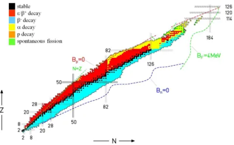
Nuclear and atomic physicists try to understand the atomic properties and interactions (mass, radius, half-life, decay modes, reaction modes, cross sections, spin, magnetic and electric dipole moments, excited states, etc.). Today there are 118 elements in the periodic system (IUPAC [13,14]) and more than 3100 nuclides were produced and partly studied experimentally (fig. 1.1). Radioactive nuclei exhibit an unique opportunity to study the structure of elements. A huge number of nuclear studies (e.g. nuclear structure, nuclear masses, astrophysics and nucleosynthesis processes, etc.) depend on the availability of radioactive-ion beams (RIBs), which are produced worldwide using particle accelerator and on-line mass separator facilities.
In the recent decades many new properties for nuclei far from stability were discovered. For example: New nuclear structures have been observed (e.g. neutron halo observed on11Li [16],
super neutron-rich nuclei [17,18]) and new elements are accessible (e.g. the discovery of a new element Z=117 [19]). 40Mg and 42Al were experimentally measured, which indicates that the
neutron drip line is placed farther from stable isotopes than expected [20], and the two-protons radioactivity was finally observed experimentally at GANIL, GSI and MSU [21,22,23]. These experiments rely on the production of intense radioactive-ion beams.
Figure 1.1– Representation of the atomic nuclei chart. The regions are presented as stable isotopes (black), or by its disintegration modes (coloured). In addition, the expected boundary limits are marked [15].
Nowadays, the forthcoming research objectives in particle accelerator and mass separator facilities need the production of “exotic” isotopes (i.e. short lived low-yield radioisotopes far-off β-stability) [24]. Moreover, one major prerequisite for extending those experiments to short lived low yield radioisotopes is the availability of pure isobaric ion beams [25]. For example, experiments performed at GANIL required highly pure18F beam for the study of the
astrophysically important 18F(p,α)15O reaction, relevant for γ-ray production in novae [26], or
the selective production of polonium isotopes at RILIS-ISOLDE for the study of its ground state and isomeric properties [6, 27].
1.2
Production of radioactive-ion beams
The Radioactive-Ion Beam (RIB) production is possible using either particle accelerator facilities or nuclear reactors. A particle accelerator is a device that uses electro-magnetic fields to drive charged particles to high speeds, and to keep them in well-defined beams for further use in engineering or scientific research. The source generates the particle beam at the beginning of the facility. The production of exotic radioactive-ion beams is complex and entail the problem of low production cross sections and yields several orders of magnitude lower than for stable isotopes. In addition the detection of short-lived isotopes is critical due to its short life-times [28]. Finally the non-selective production and the consequent contamination of the radioactive-ion beam decreases the reliability of the experiments.
1.2. Production of radioactive-ion beams
Two methods are mainly used for the production of radioactive-ion beams allowing the exploration of nuclear properties: the in-flight method (section 1.2.1) and the ISOL (Isotope Separator On-Line) technique (section 1.2.2).
1.2.1
In-Flight method
The in-flight method consist of the bombardment of a thin target with a high-intensity heavy ion beam. While the interaction occurs, either fission, fusion or fragmentation reactions will happen depending on the nature of the projectile-target couple and the energy involved in the reaction. The produced radioactive nuclei are highly ionized with an energy determined by the incoming projectile energy, the reaction Q value and the energy loss in the target. The generated radioactive-ion beams are selected with a fragment separator and can be used to initiate new nuclear reactions or to produce an ion beam (fig. 1.2).
Figure 1.2–Scheme of radioactive-ion beam production by in-flight method (also called high
energy fragmentation method). A heavy ion beam from a cyclotron or a Linear accelerator (LINAC) interacts with a thin target, producing radioactive-ion beams by nuclear reactions. The produced radioactive-ion beam is selected with a mass spectrometer.
The in-flight method can provide radioactive-ion beams with high energies and a large variety of isotopes. This method, due to the high velocity of fragments and prevention of any wall collision, gives access to very short-lived isotopes. However, the method presents several drawbacks: The process is non-selective, in some cases low production yields can be obtained, and the particle beam quality is bad, being deteriorated due to the kinematics of nuclear reactions. This production method is used in several laboratories such at S800 at MSU (USA) [29], LISE at GANIL (France) [30], GSI (Germany) [31] and RIBF at RIKEN (Japan) [32], and will be used at FRIB at MSU (USA) [33] and FAIR at GSI (Germany) [34].
1.2.2
ISOL method
Radioactive nuclei can be produced by the ISOL (Isotope Separator On-Line) method through different nuclear reactions (i.e. fission, spallation, fragmentation, etc.), when an in-coming primary beam (e.g. 500 MeV proton beam delivered at ISAC-I at TRIUMF or 40 MeV deuteron beam of SPIRAL2 at GANIL) interacts with target atoms [35, 36]. Several consecutive steps are involved in the ISOL process (fig. 1.3).
Figure 1.3–Scheme of radioactive-ion beam production by the ISOL method. The interaction
of a primary beam with a thick target induces nuclear reactions and produces radioactive atoms, which are transfered to an ionization cavity where they are ionized. In the last step, the radioactive-ion beams are extracted and mass selected with a mass separator.
The production step implies the interaction of a primary stable ion projectile beam with a thick production target. The projectile beam has enough energy to induce nuclear reactions that produce radioactive atoms. The target is thick enough to stop the reaction products. According to the primary beam and the selected target, different reaction mechanisms can produce a wide range of radioactive isotopes. The produced radioactive atoms can diffuse out of the target due to the thermal energy. To enhance this process the target is heated to high temperature (>2000 ◦
C). Afterwards, radioactive atoms effuse from the target cavity towards the ion source. The geometry of the transfer cavity has to be conceived in a way to facilitate the effusion to the ion source. The radioactive isotopes are ionized and extracted to form a radioactive-ion beam which is mass separated and can be directly used in low energy experiments or accelerated and sent to high energy experiments.
The ISOL method can provide very often high production yields (related to the thickness of the target) and it can produce a good optical-quality ion beam. However the diffusion of the elements from the target is a slow process and short-lived isotopes might not be released. In addition, the method cannot generate refractory elements or chemically active elements. The efficiency of the ISOL technique is related to the half-life of the extracted isotopes. The selectivity of the technique depends also on the chosen pair projectile-target.
1.3. Ionization methods
The ISOL method is used at ISOLDE-CERN (Switzerland) [37], ISAC at TRIUMF (Canada) [38], SPIRAL1 at GANIL (France) [30], ALTO at IPN (France) [39], and it is also planned to be used in the future project SPES under construction at LNL (Italy) [40], RAON (Korea) [41], Beijing RIB facility [42], SPIRAL2 under consideration at GANIL (France) [43], and the European installation for radioactive ion production (EURISOL) in the far future [44].
1.3
Ionization methods
An ion source is a device that creates atomic or molecular ion beams. Conventional ion sources at on-line facilities are surface ionization sources, Forced Electron Beam Induced Arc Discharge (FEBIAD) ion sources, Electron Cyclotron Resonance (ECR) ion sources and Resonant Ionization Laser Ion Source (RILIS) [45]. The ion sources dedicated to the production of Radioactive-Ion Beams (RIB) have to be highly efficient, selective (to reduce the isobar contamination) and fast (to limit the decay losses of short-lived isotopes). In addition, in the case of radioactive beams produced by the ISOL method, the ion sources must operate steadily for extended periods of time (weeks to months) in a high radiation area and operating at high temperature (>2000◦
C) to prevent the sticking of radioactive atoms or ions to cold surfaces. The choice of the most appropriate ion source is crucial to maximize the intensity, the beam quality and the number of different radioactive-ion beams that can be provided. A short introduction of the most common types of techniques for ion beam production will be given including the Resonant Ionization Laser Ion Source in this thesis.
1.3.1
Surface Ionization
The surface ionization (also named thermal ionization) is a physical process where the atoms are desorbed from a hot metallic surface due to temperature, and consequently ionized [46]. To maximize the efficiency, a high work function material (ϕ) is used in a way that atoms with low Ionization Potential (IP) may lose one electron when desorbing from the hot surface
(fig. 1.4). The surface ionization was the first type of ionization method applied at ISOL
facilities [47].
The ionization efficiency depends on the ionization potential, the surface material work function and also the plasma potential inside the hot cavity [48]. The surface ionization of positive ions is very efficient for elements with a small ionization potential like alkalis, which show high efficiencies. Other elements like rare-earth, heavier alkaline-earth and the boron group elements are surface ionized with relative low efficiencies. A dedicated surface ion source has been studied and developed for SPIRAL2 [49].
Figure 1.4– Positive surface ionization process. When an atom interacts with a hot metal surface, the energy of thermal electron emitted from the surface can be transferred to the atom resulting in ionization, if the energy exceed the element ionization potential.
Surface ionization is a competitive process and source of impurities and contamination in the Resonant Ionization Laser Ion Source (RILIS) (section 2.4).
1.3.2
Forced Electron Beam Induced Arc Discharge (FEBIAD)
The Forced Electron Beam Induced Arc Discharge (FEBIAD) is an ionization technique based on electron impact and atom-ion collisions [50, 51, 52] (fig. 1.5). In this technique an electrode grid (typically graphite) is used as anode for the continuous extraction of fast electrons from a heated cathode surface. The plasma chamber is surrounded by magnet coils for better confinement of the plasma.
Figure 1.5–Ionization by electron impact (FEBIAD ionization). A fast electron beam interacts
1.3. Ionization methods
One of the main disadvantages is the low selectivity of the process. Practically every atom entering the plasma volume can get ionized regardless its chemical nature. This ion source is used in the cases when other techniques are not able to produce required elements.
For the GANIL SPIRAL1 upgrade a FEBIAD ion source, developed by ISOLDE (VADIS VD5 [53, 54]), was coupled to the SPIRAL1 carbon target to produce new radioactive-ion beams. This source can reach 1900◦
C to decrease adsorption losses from the cavity wall. An upgrade of SPIRAL1 facility at GANIL is being studied with a new FEBIAD ion source in order to extend its production capabilities to condensable elements [55, 56].
1.3.3
Electron Cyclotron Resonance (ECR)
In the Electron Cyclotron Resonance (ECR) ion source, the ions are generated by means of ionization in a plasma generated by the process of electron cyclotron resonance. It does not have hot surfaces inside the plasma chamber, for that reason it is also called cold ion source.
The process starts with the injection of a high-frequency electromagnetic field (microwaves) into the cavity at the frequency corresponding to the electron cyclotron resonance, defined by the magnetic field applied to a region inside the volume (fig. 1.6). The magnets around the plasma chamber must provide a minimum magnetic field to generate a well for the electrons that will turn around the magnetic field lines and stay confined in the ion source where the electron cyclotron resonance condition is fulfilled:
ωc =
q · B
m (1.1)
where ωc is the angular frequency of the cyclotron motion, q is the elementary charge, B
the magnetic field strength and m is the mass of the electron. The alternating electric field of the microwaves is set to be synchronous with the gyration period of the free electrons of the gas, and increases their perpendicular kinetic energy. Subsequently, when the energized free electrons collide with the gas in the volume, they can cause ionization if their kinetic energy is larger than the ionization energy of the atoms or molecules [57].
Depending on the frequency, ECR ion sources can produce single-charged or/and multi-charged states ions. ECR ion sources are especially well adapted to the ionization of noble gases and gaseous compounds, due to the good magnetic confinement and the high energy electrons that are usually provided by these sources.
In the SPIRAL1 facility the multi-charged ECR ion source (called Nanogan III ) was con-nected to a thick carbon target allowing to produce multi-charged Radioactive-ion beams from 2001 [58]. Nanogan III was developed to produce fundamentally gaseous elements. In the
per-Figure 1.6– Diagram of the Electron Cyclotron Resonance (ECR) ionization technique. A plasma is produced due to the superposition of a magnetic field and a high-frequency electro-magnetic field (microwave) at the electron cyclotron resonance frequency (Bres).
spective of radioactive-ion beam production with SPIRAL2, the ECR Ion Source MONOBOB II (a fully radiation hard ECR ion source) was implemented [59]. It uses symmetric magnetic confinement created by four coils and it is optimized for the injection of a 2.45 GHz microwave.
1.3.4
Laser Resonance Ionization
Despite the fact that the ion beam generation methods can produce a wide range of isotopes with high performance, they often lack of selectivity due to the production of isobars and molecular side-bands. In many cases, the resolving power of mass separators is not high enough to resolve isobars and these contaminants are transmitted along with the isotope of interest [60]. In many cases, the production rate of the latter is several orders of magnitude lower than that of the isobaric contaminants [25].
The selectivity can be increased by the use of Resonant Ionization Laser Ion Source (RILIS), an elementally selective ionization process based on step-wise resonant photo-excitation (fig. 1.7). By this method the highest ion beam purity can be obtained compared to the other ionization techniques [61]. Due to this advantage, Resonant Ionization Laser Ion Sources are widely used at radioactive-ion beam facilities today. The RILIS process will be explained in detail in chapter 2.
1.4. GANIL-SPIRAL2 radioactive ion beam facility
Figure 1.7–Diagram of the multi-step resonant photo-excitation process to selectively ionize
a requested element. The resonance occurs when the laser frequency matches the atomic transition frequency, with the consequent excitation of the valence electron and ionization.
1.4
GANIL-SPIRAL2 radioactive ion beam facility
1.4.1
GANIL
GANIL (Grand Acc´el´erateur National d’Ions Lourds) is an international facility located in Caen (France) for research with stable and radioactive-ion beams. Its experimental pro-gram ranges from nuclear and atomic physics to radiotherapy, and from condensed matter to astrophysics [30].
The GANIL particle accelerator complex is constituted by 5 isosynchronous cyclotrons and can produce a wide variety of accelerated ion beams, from carbon to uranium, allowing the gen-eration of radioactive-ion beams by ISOL and in-flight methods. Its characteristics have been extended in 2001 by the SPIRAL1 facility (Syst`eme de Production d’Ions Radioactifs Acc´el´er´es en Ligne) in order to produce ISOL accelerated Radioactive-Ion Beams using projectile frag-mentation [62, 63, 64].
1.4.2
SPIRAL2
In the near future GANIL will host the SPIRAL2 facility, for fundamental nuclear physics and interdisciplinary research, which is based on a high intensity linear particle accelerator (fig. 1.8) [65,66, 67]. The SPIRAL2 project is divided into two phases:
1.4.2.1 SPIRAL2 Phase-1
The SPIRAL2 Phase-1 corresponds to the building of the superconductive LINAC accel-erator and 3 experimental areas: NFS, S3 and DESIR. The superconducting linear accelerator
(LINAC) will produce intense beams of protons (33 MeV), deuterons (40 MeV), 3.4He and
heavy ions (up to 14.5 MeV/u). The first 5 mA proton beam were produced with the RFQ (Radio Frequency Quadrupole) in December 2015.
Figure 1.8–Floor plan of the existing accelerator facility at GANIL and the planned SPIRAL2
which consist of two independent phases: The LINAC main accelerator, NFS and S3(Phase-1)
and the RIB production building (Phase-2).
The experimental areas are: NFS (Neutrons For Science) for the study and use neutron beams [68], the Super Separator Spectrometer (S3) to produce and study radioactive-ion beams by fusion evaporation [69] and DESIR (D´esint´egration, excitation et stockage d’ions radioactifs) facility for the study of very low energy exotic nuclei [70]. A low energy branch will be connected to the S3 spectrometer for the production and study of low energy beams of good optical quality,
1.4. GANIL-SPIRAL2 radioactive ion beam facility
1.4.2.2 SPIRAL2 Phase-2
The Phase-2 of SPIRAL2, still under discussion, is aimed to produce ion beams of short-lived radioactive nuclei by the ISOL method for research in fundamental physics, nuclear physics or studies of reactions in stellar processes (fig. 1.9).
The production of high intensity RIBs of neutron-rich nuclei will be based on the fission of uranium target induced by neutrons, which are obtained from a 200 kW deuteron beam impinging on graphite converter or by a direct irradiation with a deuteron, 3He, or 4He beam.
After production, the radioactive-ion beam is injected in a charge booster to increase the charge state and is then injected into the existing Cyclotron pour Ion de Moyenne Energie (CIME), which is well adapted for separation and acceleration of ions in the energy range from about 3 to 10 MeV/u for masses A ∼ 100-150.
SPIRAL2 beams can be used in the present experimental area of GANIL. The produced radioactive atoms will be ionized by different ion source techniques, according to the nature of the element and the requested characteristics of the ion beam. The ion source system can be exchanged due to ion beam requirements [56].
Figure 1.9– Scheme of radioactive-ion beam production by ISOL method for
SPIRAL2-GANIL. A deuteron beam interacts with a graphite converter that produces a neutron beam. The consequent impact of the neutron beam in a UCx target induces fission and produces radioactive atoms, which are transferred to an ionization cavity where they are ionized. Then, the radioactive-ion beams are extracted, mass selected, accelerated or sent to a low energy radioactive-ion beam facility (DESIR).
The Target Ion Source System (TISS) of SPIRAL2 Phase-2 will eventually consists of a 2.7 kg UCx target heated at 2000 K by an ohmic furnace, and the ion source connected in the opposite side of the incoming primary beam (fig. 1.10). The future target and ion source system requires a 90 degree turn between the production area and the extraction area.
In the case of RILIS, this connection is performed via a double tube in elbow-shape, where the tube close to the target acts as transfer tube and the second tube is the ionization cavity. The radioactive atoms, after effusing out of the target, will be transferred to the ionization tube, where the laser beams and the radioactive atoms interact. Then, the radioactive-ion beams are extracted by a high voltage potential.
Figure 1.10– Target module front-end picture of the Uranium Carbide target furnace and
ion source for SPIRAL2 Phase-2 in the RILIS setup. The ionizer/transfer tube assembly is marked.
The objective of this work is the study of a Resonant Ionization Laser Ion Source (RILIS), for a future implementation as part of the R&D project in the framework of SPIRAL2 Phase-2. The ionizer/transfer system behavior needed for the RILIS has been particularly studied. The developments presented here will be also useful for the laser ion source conceived for the S3 low
Chapter 2
Resonant Ionization Laser Ion Source
2.1
Resonant photo-excitation process
The Resonant Ionization Laser Ion Source (RILIS) is based on the resonant photo-excitation process. The atoms are ionized via stepwise atomic resonant excitation, which is followed by ionization in the last transition. Optical excitation occurs when the laser radiation frequency matches the atomic transition frequency [72]. Since the atoms of each element have their own specific energy level structure, the ionization process has a higher selectivity compared to other non-specific ion source generation techniques.
By this method a variety of elements are accessible to be selectively ionized, if the excitation schemes are known. 80% of chemical elements have an ionization potential between 5 and 9 eV (fig. 2.1). The approximate 2 eV needed for each atomic transition fall in the visible spectrum range. Some elements are not accessible due to their high ionization potential (noble gases or some halogens) or because the first accessible excitation step requires a light wavelength below 200 nm (i.e. this radiation will not be transmitted in air due to UV absorption) or other transitions outside of the laser tuning range. Some elements have a low ionization potential and therefore can be easily ionized. This is the case of groups I and II in the periodic table (alkali metals and alkaline earth metals). In hot-cavity RILIS, they will be present as surface ioniza-tion contaminants, due to the resistive heating of the ionizaioniza-tion cavity to high temperatures (typically 2000 K).
The resonant ionization process starts with the atom in its ground state or a low-lying thermally populated state. Valence electrons are stepwise excited by resonant absorption of laser light. They are advanced to a first excited state (FES) using a strong atomic transition. For most elements, suitable transitions for this excitation step are in the blue (energy of photons 2.5-3.5 eV) or ultraviolet (energy of photons >3.5 eV) wavelength regions.
Figure 2.1– Ionization potential for several chemical elements. It is possible to observe that the average ionization potential does not exceed 9 eV [73].
The saturation of each transition level is desired for an efficient ion production. This situation is experimentally verified by measurements of saturation curves and adequate setting of injected laser power (section 3.4.2).
The first transition generally has a cross section in the order of 10−10
cm2 and it is easily
saturated with a microjule laser pulse. However, for the remaining atomic transitions, higher power is needed for saturation due to lower cross sections. Following the first step excitation, the atom is driven to a higher excited state by another strong atomic transition connected to the first excited state. In some cases, this second excited state (SES) can already generate ionization, if located close to or even above the ionization potential. If not, a third excitation step will then ionize the atom. With the combination of two or three laser beams it is thus possible to ionize the predominant part of the elements of the periodic table.
The final atomic transition is crucial for the efficiency of the method. Fortunately there are different ways to realize this final step (fig. 2.2). The ionizing step could be reached via non-resonant transition into the continuum, above the first ionization potential of the element, or resonantly via an auto-ionizing state (i.e. an eigenstate located above the first ionization potential) or Rydberg states (a highly excited level with high principal quantum number n, located just below the ionization potential). The disadvantage of the non-resonant process is its relatively low cross section (∼10−17 cm2), which is several orders of magnitude smaller than
for transitions using auto-ionizing states or Rydberg states. Both, ionization via Rydberg or auto-ionizing states offers higher cross section because they are resonant processes (∼10−12
2.2. RILIS requirements
Figure 2.2–Alternative ways to reach the ionization potential for the final step: Auto-ionizing
resonances, non-resonant ionization to the continuum and excitation of Rydberg-states. The cross section of each atomic transition is also indicated.
The atoms excited to high-lying Rydberg states are ionized in combination with a non-resonant mechanism of ionization: Thermal radiation, collisions, electric fields, IR lasers, etc. The ionization of laser-excited Rydberg states in a hot cavity is predominantly carried out by the blackbody radiation field. For an efficient and selective ionization, an individual excitation scheme and strong atomic transitions are needed for each element of interest. The first two excitation steps can be typically found in literature (NIST database [74] or Kurucz tables [75]) while extensive spectroscopic investigations are usually needed to find suitable high-lying Rydberg states or auto-ionizing states. In addition, some of the transitions are not accessible within the available wavelength tuning range of the laser system used. For this reason, high-power lasers are often applied in the last step for a non-resonant transition to the continuum.
2.2
RILIS requirements
A Resonant Ionization Laser Ion Source is composed of two parts: The interaction device (ion source) and the laser system (fig. 2.3). The ion source is connected to the hot furnace target area. It is installed on a high voltage (HV) platform at the isotope production front end of the on-line mass separator. This is often based technically on a conventional surface ionization source and ideally provides confinement of the radioactive atomic vapor until it is ionized. The laser system allows the resonant ionization of radioactive atoms. The laser laboratory is separated from the target ion source area in a temperature controlled room.
Figure 2.3– Resonant Ionization Laser Ion Source diagram. The radioactive atoms coming from the target are introduced into the ion source. Here the laser beams produce the resonant photo-excitation of the radioactive atoms and a radioactive-ion beam is generated.
The laser system consists of a set of two or three tunable lasers, which allow to select the proper wavelength for resonant photo-excitation with a high energy per pulse. The laser beams, which are overlapped in space and time, are transported from the laser room to the ion source through the mass separator and the extraction system, and then the ionization takes place inside the ionization tube. Finally, the generated radioactive-ion beams are extracted and mass selected. An introduction to the laser technology and a description of its origin can be found in appendix A.
The main requirements of a laser ion source for on-line applications are universality, se-lectivity, efficiency, reliability and rapidity [48]. One of the fundamental characteristics that motivated the development of RILIS is the universality of the method. As already mentioned, 80% of the chemical elements of the periodic table can be ionized by the RILIS technique. The selectivity (ionization of one element at a time) is the strong point of the RILIS technique and its main advantage in comparison with other ion generation techniques [76]. The com-bination of laser element selective ionization and mass separation allows to select precisely a single isotope (fig. 2.4). The selectivity can be improved by modifying the conventional RILIS configuration (i.e. the laser-atom interaction) or by use of purification equipments to the RILIS line (section 2.4.1). These methods allow the production of highly pure ion beams.
The efficiency of the technique depends on the atomic species and the ionization schemes chosen. For some elements, the efficiency can reach values up to 40% [77]. In general for most of the elements, ionization efficiencies vary between 5 and 30% [1]. The reliability of RILIS is determined by the long-term stability of the laser system. The capability to adapt the method to any possible setting without a big effort is called the versatility of the system. The laser system is outside the radiation area and the only thing that remains in the radiation area is the ionization tube, which is simple and robust. Finally, the rapid nature of the process allows to reduce decay losses in the ion source. The ionization time is negligible compared to the release time from the production target, and the effusion time in the target and ion source system.
2.2. RILIS requirements
Figure 2.4– Schematic explanation of the RILIS Z-selectivity. In this case, 125Sn is selected.
All different isotopes of the same element are ionized (blue). Then the selectivity takes place when the mass of the isotope is selected by the mass spectrometer (yellow). The combination of element selective resonant laser ionization and mass selectivity by means of a mass separator ensures the nuclei selectivity (green).
2.2.1
Laser specifications for the RILIS technique
There is a wide variety of lasers, but the RILIS technique demands some specific laser re-quirements in order to access many elements. For that reason, the possible laser types that finally can be used are limited. A suitable laser for the RILIS has to fulfill the following require-ments: High output power, high repetition rate, appropriate wavelength selection, possibility for easy generation of higher harmonics, GHz spectral linewidth and suitable synchronization between pulses from several laser resonators.
2.2.1.1 Pulsed laser
The output power has to be sufficient to transfer the energy to the atomic transition for efficient resonant photo-excitation. Non-resonant transitions (specially for the ionization step) have a cross-section below 10−17 cm2. In this case, a CW (continuous wave) laser beam from a
frequency doubled Nd:YAG laser would require several kW for a 3 mm spot size to saturate a non-resonant transition [78]. A pulsed laser is a way to reach a peak power close to this value. The Q-switch technique can be used to deliver pulsed laser beams with a large amount of light radiation in a short period of time, where the peak power depends on the pulse length.
This technique is based on the accumulation of the energy provided by the pump laser and a sudden release afterwards. This is reached by increasing the resonator losses controlled by the Q-factor (Q stands for quality). During the low Q-factor, while the gain medium is being pumped, the high cavity losses inhibits feed-back in the system and prevents the laser emission. The energy is accumulated in the form of population inversion between the fundamental and the excited state, if the accumulation time is shorter compared to the decay period.
Figure 2.5–Diagram of Q-switch mechanism. The reduction of the cavity losses in population
inversion causes the emission of an intense laser pulse.
Then, the system is suddenly changed to a high Q-factor (or low loss mode) if the system is in a high grade of population inversion. Then induced emission occurs and will be strongly amplified, increasing the number of photons in the cavity and causing a sudden emission of energy in a form of an intense laser pulse (fig. 2.5). The laser pulse is generated in a short pulse due to the immediate exhaustion of the accumulated energy and decrease of population inversion, until the gain medium only provides rather low gain and the laser emission stops. If the Q-factor is switched again to a low value (high loss mode) the system restarts a cycle and the gain medium starts again to accumulate energy [79].
2.2.1.2 Repetition rate
For efficient ion-source operation the temporal and spatial overlap of laser light and atoms has to be optimized. In a hot-cavity typically there is a continuous flow of atoms through the ionizer, that when using pulsed lasers is only temporally filled with the laser light. The inverse of the atom residence time within the laser interaction region gives the required laser
![Figure 2.12– Scheme of the dual chamber laser ion source gas cell [105].](https://thumb-eu.123doks.com/thumbv2/123doknet/14611554.732515/55.892.248.629.216.558/figure-scheme-dual-chamber-laser-ion-source-cell.webp)
![Figure 2.18– Schematic drawing of the target and hot cavity ionizer setup at the ISOLDE-3 mass separator [95].](https://thumb-eu.123doks.com/thumbv2/123doknet/14611554.732515/68.892.293.585.594.918/figure-schematic-drawing-target-cavity-ionizer-isolde-separator.webp)
![Figure 2.19– The former scheme of the laser ion source system at ISOLDE, which included a dye laser system (above) and an ionizer and mass selector (below) [161].](https://thumb-eu.123doks.com/thumbv2/123doknet/14611554.732515/69.892.223.677.589.914/figure-scheme-laser-source-isolde-included-ionizer-selector.webp)


![Figure 3.15– Zinc vapor pressure calculation. If an experimental pressure of 1·10 − 6 mbar is considered, the evaporation temperature would be about 450 K [189].](https://thumb-eu.123doks.com/thumbv2/123doknet/14611554.732515/88.892.243.642.277.508/figure-pressure-calculation-experimental-pressure-considered-evaporation-temperature.webp)