HAL Id: tel-00965934
https://tel.archives-ouvertes.fr/tel-00965934
Submitted on 25 Mar 2014HAL is a multi-disciplinary open access archive for the deposit and dissemination of sci-entific research documents, whether they are pub-lished or not. The documents may come from teaching and research institutions in France or
L’archive ouverte pluridisciplinaire HAL, est destinée au dépôt et à la diffusion de documents scientifiques de niveau recherche, publiés ou non, émanant des établissements d’enseignement et de recherche français ou étrangers, des laboratoires Manzoor Ahmad. Modeling and verification of functional and non functional requirements of ambient, self adaptative systems. Other [cs.OH]. Université Toulouse le Mirail - Toulouse II, 2013. English. �NNT : 2013TOU20098�. �tel-00965934�
THÈSE
THÈSE
En vue de l'obtention du
DOCTORAT DE L’UNIVERSITÉ DE TOULOUSE
DOCTORAT DE L’UNIVERSITÉ DE TOULOUSE
Délivré parl'Université Toulouse II - Le Mirail Discipline ou spécialité :
Informatique
JURY
Charles CONSEL - Professor, University of Bordeaux , France (Examiner)
João ARAÚJO - Assistant Professor, Universidade Nova de Lisboa, Portugal (Examiner) Pierre-Jean CHARREL - Professor, University of Toulouse, France (Member)
Régine LALEAU - Professor, Université Paris-Est Créteil, France (Member) Jean-Michel BRUEL - Professor, University of Toulouse, France (Supervisor) Nicolas BELLOIR - Maître de Conférences, UPPA Pau, France (Co-Supervisor)
Ecole doctorale : Mathématiques Informatique Télécommunications (MITT) Unité de recherche : Institut de Recherche en Informatique de Toulouse (IRIT)
Directeur(s) de Thèse : Jean-Michel BRUEL et Nicolas BELLOIR Présentée et soutenue par
Manzoor AHMAD Le 07-10-2013
Titre :
Modeling and Verification of Functional and Non Functional
Requirements of Ambient, Self-Adaptive Systems
Abstract
The context of this research work is situated in the field of Software Engineering for Self Adaptive Systems. Software Engineering applies a systematic approach to the development, operation, and maintenance of a software product using a sequence of activities. Our work resides in the very early stages of the software development life cycle i.e. at the Requirements Engineering phase. We focus on requirements elicitation, modeling and verification aspects of the Requirements Engineering process.Due to the continuous growth in size, complexity, heterogeneity and the inherent un-certainty of systems, it becomes increasingly necessary for computing based systems to dynamically self adapt to changing environmental conditions, these systems are called Self Adaptive Systems. These systems modify their behavior at run-time in response to changing environmental conditions. In order to take into account the changing environmental factors, Requirements Engineering languages must deal with the inherent uncertainty present in these systems, which we can capture during the early phases of its development life cycle. Requirements provide the basis for estimating costs and schedules as well as developing design and testing specifications. Changes identified during the later stages of the software development life cycle are hard to reflect and impacts the cost, schedule, and quality of the resulting software product. For Self Adaptive Systems, Non Functional Requirements play an important role, and one has to identify as early as possible those Non Functional Requirements that are adaptable. Non Functional Requirements are requirements that are not specifically concerned with the functionality of a system, they place restrictions on the product being developed and the development process.
The overall contribution of this thesis is to propose an integrated approach for modeling and verifying the requirements of Self Adaptive Systems using Model Driven Engineering techniques. Model Driven Engineering is primarily concerned with reducing the gap between problem and software implementation domains through the use of technologies that support systematic transformation of problem level abstractions to software implementations. By using these techniques, we have bridged this gap through the use of models that describe complex systems at multiple levels of abstraction and through automated support for transforming and analyzing these models. We take requirements as input and divide it into Functional and Non Functional Requirements. We then use a process to identify those requirements that are adaptable and those that cannot be changed. We then introduce the concepts of Goal Oriented Requirements Engineering for modeling the requirements of Self Adaptive Systems, where
Acknowledgement
Completing my PhD degree is probably the most challenging activity of my first 32 years of life. The best and worst moments of my doctoral journey have been shared with many people. It has been a great privilege to spend several years in MACAO (IRIT) at University of Toulouse, and its members will always remain dear to me.Foremost, I would like to express my sincere gratitude to my advisor Prof. Jean-Michel BRUEL for the continuous support during my Ph.D study and research, for his patience, motivation, enthusiasm, and immense knowledge. I could not have imagined having a better advisor and mentor for my Ph.D study. I would also like to express my sincere gratitude to my co-advisor Nicolas BELLOIR. Their guidance helped me in all the time of research and writing of this thesis.
Besides my advisors, I would like to thank the thesis committee: Prof. Charles CONSEL, Assistant Prof. João ARAÚJO, Prof. Pierre-Jean CHARREL and Prof. Régine LALEAU for their encouragement, insightful comments, and questions. It is no easy task, reviewing a thesis, and I am grateful for their thoughtful and detailed comments.
I would like to thank Cristophe GNAHO and Farida SEMMAK whose work on goal oriented requirements engineering and the discussions that we have had inspired us to integrate it in our research work.
I thank my fellow lab mates specially Iulia DRAGOMIR for the healthy discussion that we have had on properties verification.
I also offer my gratitude to HEC (Higher Education Commission) of the Government of Pakistan which financed this thesis in its early days.
I would like to thank my parents, their love provided me inspiration and was my driving force. I owe them everything and wish I could show them just how much I love and appreciate them.
I would like to thank my family and friends: my brother and sisters who were always there to encourage and motivate me.
Last but not the least, I would like to thank my wife Faiza AHMAD whose love and encouragement allowed me to finish this journey. She was always there cheering me up and stood by me through good and bad times.
Contents
Acknowledgement v Contents vii List of Figures xi 1 Introduction 1 1.1 Problem Statement . . . 21.2 Objectives of the Thesis . . . 2
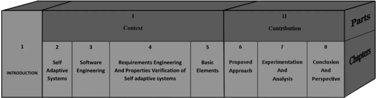
1.3 Structure of the Thesis . . . 3
I Context 7 2 Self Adaptive Systems 9 2.1 What are Self Adaptive Systems? . . . 10
2.2 How Self Adaptive Systems Differs from other Systems? . . . 10
2.3 Self Adaptive Systems Examples . . . 11
2.4 From Requirements Discovery to Adaptation Choices of Self Adaptive Systems 12 2.5 Conclusion . . . 12
3 Software Engineering 15 3.1 Software Engineering. . . 16
3.1.1 What is Software Engineering . . . 16
3.1.2 Origin of Software Engineering. . . 16
3.1.3 Activities of Software Engineering . . . 16
3.2 Model Driven Engineering. . . 19
3.2.1 General Principles of Model Driven Engineering . . . 19
3.2.2 Why Model Driven Engineering for Self Adaptive Systems? . . . 23
3.3 Requirements Engineering. . . 23
3.3.1 The Importance of Requirements Engineering . . . 23
3.3.2 Definition of Requirement. . . 24
4 Requirements Engineering & Properties Verification of Self Adaptive Systems 33
4.1 Requirements Engineering for Self Adaptive Systems . . . 34
4.1.1 Levels of Requirement Engineering for Modeling . . . 34
4.1.2 REcording of Assumptions in RE . . . 35
4.1.3 Awareness Requirements . . . 36
4.1.4 RELAX augmented with CLAIMS . . . 36
4.1.5 AutoRELAX . . . 37
4.1.6 Fuzzy Live Adaptive Goals for Self-Adaptive Systems . . . 37
4.1.7 Discussion . . . 38
4.2 Properties Verification of Self Adaptive Systems . . . 39
4.2.1 MEDISTAM-RT . . . 39
4.2.2 Timed UML and RT-LOTOS Environment . . . 39
4.2.3 UPPAAL . . . 40
4.2.4 SysML with B Specifications . . . 40
4.2.5 The OMEGA2 UML/SysML Profile . . . 41
4.2.6 IFx Toolset . . . 41 4.2.7 Discussion . . . 41 4.3 Conclusion . . . 42 5 Basic Elements 43 5.1 RELAX . . . 44 5.1.1 RELAX Vocabulary . . . 44
5.1.2 RELAX-ed v/s Invariant Requirements . . . 44
5.1.3 RELAX Operators . . . 45 5.1.4 RELAX Grammar. . . 45 5.1.5 RELAX Process . . . 47 5.1.6 Discussion . . . 48 5.2 SysML/KAOS . . . 49 5.2.1 SysML . . . 49 5.2.2 KAOS . . . 51 5.2.3 Why SysML/KAOS? . . . 51
5.2.4 SysML/KAOS Meta Model . . . 52
Contents
5.3 The OMEGA2 UML/SysML Profile and IFx Toolset . . . 53
5.3.1 The OMEGA2 Profile . . . 54
5.3.2 IFx Toolset . . . 56
5.4 Conclusion . . . 58
II Contribution 59 6 Proposed Approach 61 6.1 Overall View of our Proposed Approach . . . 62
6.1.1 Problem 1 . . . 62
6.1.2 Problem 2 . . . 62
6.1.3 Problem 3 . . . 64
6.2 The Proposed Approach . . . 64
6.3 The Solutions . . . 66
6.3.1 Solution 1 . . . 66
6.3.2 Solution 2 . . . 66
6.3.3 RELAX Improvements . . . 67
6.4 Integration of the Approaches. . . 67
6.4.1 Relatonship b/w RELAX, SysML/KAOS and SysML . . . 68
6.4.2 Uncertainty Factors/Impacts . . . 69
6.4.3 Verification of Ambient System’s Properties through Formal Methods . 69 6.4.4 Discussion . . . 70
6.5 Tools Support . . . 70
6.5.1 DSL for RELAX . . . 71
6.5.2 RELAX Editor. . . 73
6.5.3 RELAX to SysML/Kaos Transformation . . . 74
6.6 Conclusion . . . 77
7 Experimentation And Analysis 79 7.1 Requirements Modeling of the AAL Case Study . . . 80
7.1.1 The AAL Case Study. . . 80
7.1.2 Discussion . . . 83
7.2 Properties Verification of the AAL system with OMEGA2/IFx Profile and Toolset 83 7.2.1 Modeling the AAL system with OMEGA2 Profile . . . 84
7.2.2 Properties Verification of the AAL system . . . 87
7.3 Requirements Modeling of the bCMS Case Study . . . 94
7.3.1 The bCMS Case Study . . . 94
7.3.2 High Level Goal Model . . . 94
7.3.3 Low Level Goal Model. . . 96
7.3.4 Discussion . . . 97
8.3.3 Perspective for the Empirical Studies . . . 106 Author’s Bibliography 107 International Conferences . . . 107 National Conferences . . . 107 Workshops . . . 107 Bibliography 109 Acronyms 117
List of Figures
1.1 Thesis Chapters Organization . . . 4
3.1 The Software Engineering Process [86]. . . 18
3.2 Relationship between System and Model [19]. . . 20
3.3 The 3+1 MDA Architecture [18]. . . 22
3.4 Model Transformation Example [44] . . . 23
3.5 Projects Success Rates 1994 to 2009 [40] . . . 24
3.6 Reasons for Resource Overspend [39] . . . 25
3.7 Non Functional Requirement Definitions [35]. . . 26
3.8 The Requirements Engineering Process [86]. . . 27
3.9 KAOS Models . . . 30
5.1 Relax Operators [96] . . . 46
5.2 Relax Process [96] . . . 47
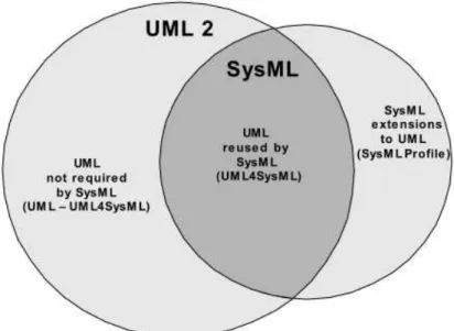
5.3 SysML UML Relationship . . . 50
5.4 SysML Diagrams . . . 50
5.5 SysML/Kaos Meta Model [36] . . . 52
5.6 IFX Workflow [91]. . . 56
5.7 If2gui Interface [91] . . . 57
6.1 Conventional Requirements Modeling using SysML/Kaos . . . 63
6.2 Conventional Properties Verification using OMEGA2/IFx . . . 63
6.3 Overall View of Our Approach . . . 65
6.4 Overall View of Our Approach Showing Input Output and Contributions . . . 67
6.5 Relationship b/w SysML/Kaos SysML and Relax . . . 70
6.6 Relax Grammar . . . 71
6.7 Generated Requirement Diagram . . . 72
6.8 Generated Code . . . 72
6.9 RELAX File . . . 73
6.10 RELAX Model Example . . . 74
6.11 Meta Models Paths . . . 74
6.12 In and Out Declarations . . . 75
7.3 High Level Goal Model . . . 82
7.4 Security Goal Model . . . 83
7.5 Main Internal Block Diagram . . . 85
7.6 AAL System Blocks . . . 86
7.7 Fridge Internal Block Diagram . . . 86
7.8 Patient State Machine Diagram . . . 87
7.9 Food State Machine Diagram . . . 88
7.10 Property1 State Machine Diagram . . . 89
7.11 Property2 State Machine Diagram . . . 90
7.12 Property3 State Machine Diagram . . . 91
7.13 XMI to IF Compilation . . . 91
7.14 IF to Executable file Compilation . . . 92
7.15 Model Checker results in Error Scenarios . . . 92
7.16 Initial Simulation Interface. . . 93
7.17 Error State Food Observer Simulation Interface . . . 93
7.18 Model checking successful . . . 93
7.19 bCMS Case Study Overall View. . . 94
7.20 Availability RELAX-ed Requirement Uncertainty Factors . . . 95
7.21 High Level Goal Model . . . 96
7.22 Integrity RELAX-ed Requirement Uncertainty Factors . . . 96
7.23 Integrity Goal Model . . . 97
7.24 Assessement Table . . . 98
7.25 Pros and Cons of our Proposed Approach . . . 99
CHAPTER
1
Introduction
Contents
1.1 Problem Statement . . . 2
1.2 Objectives of the Thesis . . . 2
a range of environmental conditions and contexts, but the exact nature of these contexts remains imperfectly understood. A feature common to all the previous works regarding Requirements Engineering (RE) forSASis that they assume that all adaptation choices are known and enumerated at design time and does not take unanticipated adaptations into account. The fact that the point of adaptation forSASshould be identified as early as possible drive the research on these systems. We base our hypothesis on how to identify the point of adaptation while defining the requirements for these systems and how to verify these requirements while keeping in mind the adaptability associated with these systems.
We have identified some problems associated with requirements modeling and verification using existing approaches. On one hand, existing requirements modeling approaches do not take into account the uncertainty factors associated with SAS, on the other, hand we are exposed to the state space explosion problems associated with existing properties verification techniques for these systems.
1.2
Objectives of the Thesis
The main objective of this thesis is to provide an integrated approach to identify the point of flexibility as early as possible while defining the requirements ofSASand to provide a mechanism for verifying the requirements of these systems. We are of the view that, on one hand, requirements forSASshould consider the notion of uncertainty while defining it, on the other hand, there should be a way to verify these requirements as early as possible, even before the development of these systems starts. In order to handle the notion of uncertainty inSAS,RElanguages for these systems should include explicit constructs for identifying the point of flexibility in its requirements [96]. Goal Oriented Requirements Engineering (GORE) techniques can be used to define and model the requirements ofSAS[37,100,58,99] and we aim to provide an integrated approach where we can define and model the requirements of these systems to obtain a detailed description of the system and its environment.
We base our proposition on using Relax [96] which is an RE language for SAS and which helps in the differentiation of those requirements that can be Relax-ed from those requirements that can not be changed. ForSAS, Relax-ed requirements play an important role as these are associated with the adaptability features of these systems. We then integrate Relax with SysML/Kaos [36] which is aGORE approach for modeling the requirements ofSAS. Then we aim to provide an efficient approach for verifying the properties of these
1.3. Structure of the Thesis
systems. The concepts of Model Driven Engineering (MDE) are used at each step of our proposed approach as it is the main theme of our research team1 and also due to the
benefits associated with it [33].MDEis primarily concerned with reducing the gap between problem and software implementation domains through the use of technologies that support systematic transformation of problem-level abstractions to software implementations.
Our proposed approach comprises of some tools and processes to address the problems defined above, which are listed below.
1. To bridge the gap between requirements and the overall system model, we provide a Domain Specific Language (DSL) for Relax, which takes requirements in textual format as input and transform it into SysML requirements diagram.
2. To automate the requirements ofSASby taking into account the different uncertainty factors associated with each Relax-ed requirement, we provide a tool called Relax COOL editor.
3. To take benefits ofGORE approaches, we provide a correlation between Relax and SysML/Kaos concepts.
4. To use SysML/Kaos in the context of SAS, we provide a mechanism so that only Relax-ed requirements are injected into SysML/Kaos and not theNFRsin general. 5. To model the Relax-ed requirements in the form of goal models, these requirements
are transformed into SysML/Kaos goal concepts using the correlation table.
6. The validation of our integrated approach by applying it on Ambient Assisted Living (AAL) and barbados Car Crash Crisis Management System (bCMS) case studies. 7. To verify some properties of theAAL against the system design, we adapt the profile
and the toolset used for verification to take into account the adaptability features associated withSASrequirements.
The choice of Relax is motivated by the fact that it avoids the problem posed by unan-ticipated adaptations, i.e. by specifying declaratively the ways in which a requirement may be Relax-ed. Relax does not require all possible alternative adaptations to be specified duringRE. This flexibility leaves open the design choice as to how to achieve adaptation and therefore supports designs based on adaptation rules, planning algorithms, control theory algorithms, etc. This work resides in the framework of self adaptation but we do not treat the development of self adaptation mechanisms as we are at the very early stage of theSAS
development life cycle.
1.3
Structure of the Thesis
The thesis is organized as follows. In chapter 2, I give a description of the main context of our work i.e. what isSASand how it differs from other systems, I then give few examples of SAS. In chapter 3, I give a description of Software Engineering (SE) and what are its
Figure 1.1: Thesis Chapters Organization
activities, then I introduce MDE along with its basic concepts and show why is it useful to use MDE techniques for SAS. As this thesis is centered around defining an integrated approach for theREofSAS, I describe the different approaches ofRE. GOREtechniques are detailed as we base our proposition on using these techniques for defining and modeling the requirements ofSAS. chapter4gives a description of the state of the art of the different approaches i.e. REforSASand properties verification using formal methods. In chapter5, I describe Relax, which is anRElanguage forSASand SysML/Kaos which is an extension of the SysML requirements model with concepts of the Kaos goal model. Both Relax and SysML/Kaos serve us as a starting point for proposing our integrated approach. I then introduce OMEGA2/IFx profile and toolset that we used for the properties verification and model simulation of theSAS. OMEGA2 is an executable Uml/SysML profile used for the formal specification and validation of critical real-time systems. It is based on a subset of Uml 2.2/SysML 1.1 containing the main constructs for defining the system structure and behavior. The OMEGA2 Profile is supported by the IFx toolset which provides mechanisms for the model simulation and properties verification ofSAS. chapter6gives an overall view of our proposed approach, defining the various processes, tools and documents used in it. I start with introducing the reasons that motivated us to propose this approach by showing some problems that we identified with existing approaches. I then explain the need for an integrated approach which takes into account the different features that we propose and to provide an integrated tooling environment for dealing with the identified problems. I then give a description of the tools that we developed in order to validate the proposed approach. The tools comprises of: aDSLfor Relax which is acting as a bridge between the requirements and overall system model and using thisDSL, we have transformed requirements in textual format to a graphical format i.e. SysML requirements diagram using Relax grammar, a Relax editor which is capabale of automating the Relax-ed requirements by taking into account the uncertainty factors associated with each Relax-ed requirement, a Relax2SysML/Kaos editor which models the requirements of the case studies that we have worked with and which is the result of the application of transformation rules from Relax-ed requirements into SysML/Kaos goal concepts. In order to validate the proposed approach, chapter 7
gives a description of the two case studies i.e. AALandbCMS, and the modeling of some of its requirements. I then show the verification of some of the properties of the AALcase
1.3. Structure of the Thesis
study using OMEGA2/IFx profile and toolset. This chapter also shows an assessment of the proposed approach in terms of the problems identified and the solution provided by using it. chapter8shows the summary of this thesis and the perspectives that we identified. Figure1.1
Part I
CHAPTER
2
Self Adaptive Systems
Contents
2.1 What are Self Adaptive Systems? . . . 10 2.2 How Self Adaptive Systems Differs from other Systems? . . . 10 2.3 Self Adaptive Systems Examples. . . 11 2.4 From Requirements Discovery to Adaptation Choices of Self Adaptive Systems 12
fixed if the environment in which the system operates is stable [95].
As applications continue to grow in size, complexity, and heterogeneity, it becomes in-creasingly necessary for computing based systems to dynamically self adapt to changing environmental conditions. These systems are called Dynamic Adaptive Systems (DAS) [96]. Example applications that require DAS capabilities include automotive systems, telecom-munication systems, environmental monitoring, and power grid management systems. The distributed nature ofDASand changing environmental factors (including human interaction) makes it difficult to anticipate all the explicit states in which the system will be during its lifetime. As such, aDAS needs to be able to tolerate a range of environmental conditions and contexts, but the exact nature of these contexts remains imperfectly understood. One overarching challenge in developingDAStherefore, is how to handle the inherent uncertainty posed by the respective application domains.
2.2
How Self Adaptive Systems Differs from other Systems?
The complexity of current software systems has led the SE community to investigate innovative ways of developing, deploying, managing and evolving software-intensive systems and services. In addition to the ever increasing complexity, software systems must become more versatile, flexible, resilient, dependable, energy-efficient, recoverable, customizable, configurable, and self-optimizing by adapting to changes that may occur in their operational contexts, environments and system requirements. Therefore, self-adaptation:
"systems that are able to modify their behavior and/or structure in response to their perception of the environment and the system itself, and their goals"
has become an important research topic in many diverse application areas.
It is generally accepted that errors in requirements are very costly to fix [62]. The avoidance of erroneous requirements is particularly important for the emerging class of systems that need to adapt dynamically to changes in their environment. Many suchDAS
are being conceived for applications that require a high degree of assurance [85], in which an erroneous requirement may result in a failure at run-time that has serious consequences. The requirement for high assurance is not unique toDAS, but the requirement for dynamic adaptation introduces complexity of a kind not seen in conventional systems where adaptation, if it is needed at all, can be done off-line. This dynamic adaptation consequent complexity is
2.3. Self Adaptive Systems Examples
manifested at all levels, from the services offered by the run-time platform, to the analytical tools needed to understand the environment in which theDASmust operate.
DASare systems designed to continuously monitor their environment and then adapt their behavior in response to changing environmental conditions. DAStend to be cyber-physical systems, where the physical environment is tightly intertwined with the computing-based system. For these systems, the software may need to be reconfigured at run time (e.g., software uploaded or removed) in order to handle new environmental conditions [20].
REis concerned with what a system ought to do and within which constraints it must do it. REforSAS, therefore, must address what adaptations are possible and what constrains how those adaptations are carried out. In particular, questions to be addressed include: what aspects of the environment are relevant for adaptation? Which requirements are allowed to vary or evolve at run-time and which must always be maintained? In short,REforSASmust deal with uncertainty because the expectations on the environment frequently vary over time. The need forDASis typically due to two key sources of uncertainty. First is the uncertainty due to changing environmental conditions, such as sensor failures, noisy networks, malicious threats, and unexpected (human) input; the term environmental uncertainty is used to capture this class of uncertainty. IBM, for example, originally proposed the area of autonomic com-puting [48] to handle environmental uncertainty, thereby enabling computing-based systems to use high-level application goals and requirements to guide run-time self-management, including self-monitoring, self-healing, and self-configuration. A second form of uncertainty is behavioral uncertainty. Whereas environmental uncertainty refers to maintaining the same requirements in unknown contexts, behavioral uncertainty refers to situations where the requirements themselves need to change. For example, the requirements of a space probe may change mid flight in order to pursue science opportunities not foreseen by the designers. It is difficult to know all requirements changes at design time and, in particular, it may not be possible to enumerate all possible alternatives [96].
An increasingly significant requisite for software based systems is the ability to handle re-source variability, ever-changing user needs and system faults. Certain standard programming practices, such as capacitating extensive error handling capabilities through exception catch-ing schemes, do contribute towards rendercatch-ing systems fault-tolerant or self-adaptive, however, these methods are tightly coupled with software codes and are highly application-specific [34].
2.3
Self Adaptive Systems Examples
SASlikeAALare common in industrialized countries. Below, I cite few examples of such
SAS.
– The Aware Home Research Initiative (AHRI)1 at Georgia Institute of Technology is
an interdisciplinary research endeavor aimed at addressing the fundamental technical, design, and social challenges for people in a home setting. Researchers at theAHRI
– Mary AAL home3: Mary is a patient and she need hypo caloric diet. She needs
to maintain minimum liquid intake and the various sensor enabled tools helps her maintain her daily intake of food and water. Advanced smart homes, such as Mary’s
AAL, rely on adaptivity to work properly.
– DiaSuiteBox4 is an Open application platform for smart homes. It proposes an
applica-tion store that gathers the devices deployed at home. The DiaSuiteBox platform runs an open-ended set of applications leveraging a range of appliances and web services. We use Mary’sAAL home case study for the validation of our proposed approach. We model the requirements and then verify some of the properties of theAALcase study using our proposed approach.
2.4
From Requirements Discovery to Adaptation Choices of Self
Adaptive Systems
Goal based modeling notations has been applied to the discovery and specification of
DASrequirements [96] such as i* [98]. Goal models have proven to be useful for specifying the adaptation choices that a DAS must make [37, 58] as well as for the specification of monitoring and switching between adaptive behaviors [81]. A particular strength of goal based modeling is that it supports the modeling of non-functional trade-offs, which can be used to capture some elements of environmental uncertainty. [59] show that requirements goal models can be used as a foundation for designing software that supports a space of behaviours, all delivering the same function, and that is able to select at runtime the best behaviour based on the current context. The advantages of this approach include the support for traceability of software design to requirements as well as for the exploration of alternatives and for their analysis with respect to quality concerns of stakeholders.
2.5
Conclusion
In this chapter, I show a description of the context of our work i.e. SAS. Then, I describe the specificity of these systems and show how these systems differs from other systems. I
2. ❤tt♣✿✴✴♠✐✳✐✉t✲❜❧❛❣♥❛❝✳❢r✴
3. ❤tt♣✿✴✴✇✇✇✳✐❡s❡✳❢r❛✉♥❤♦❢❡r✳❞❡✴❢❤❣✴✐❡s❡✴♣r♦❥❡❝ts✴♠❡❞♣r♦❥❡❝ts✴❛❛❧✲❧❛❜✴✐♥❞❡①✳❥s♣
2.5. Conclusion
then cite few examples ofSASas these systems like Mary’sAALare developed to facilitate the daily lives of the patient. The technologies show promise in helping people to live independently and in comfort. As our work is about the REofSAS, I talk about the very initial stages of the SAS life cycle as we are interested in providing a framework for self adaptation but not any mechanisms for achieving it.
CHAPTER
3
Software Engineering
Contents
3.1 Software Engineering . . . 16 3.1.1 What is Software Engineering. . . 16 3.1.2 Origin of Software Engineering . . . 16 3.1.3 Activities of Software Engineering . . . 16 3.2 Model Driven Engineering . . . 19 3.2.1 General Principles of Model Driven Engineering. . . 19 3.2.2 Why Model Driven Engineering for Self Adaptive Systems? . . . 23 3.3 Requirements Engineering . . . 23 3.3.1 The Importance of Requirements Engineering . . . 23 3.3.2 Definition of Requirement . . . 24 3.3.3 Functional Requirements v/s Non Functional Requirements. . . 25 3.3.4 Activities of Requirements Engineering . . . 25 3.4 Approaches of Requirements Engineering . . . 26 3.4.1 Scenario Based Requirements Engineering . . . 27 3.4.2 Aspect Oriented Requirement Engineering . . . 27 3.4.3 Problem Frame Requirements Engineering . . . 28 3.4.4 Goal Oriented Requirement Engineering . . . 28 3.4.5 Discussion . . . 31 3.5 Conclusion . . . 32
of materials, governed by physical laws, or by manufacturing processes. This simplifiesSE, as there are no natural limits to the potential of software. However, because of the lack of physical constraints, software systems can quickly become extremely complex, difficult to understand, and expensive to change. This is why they need specific engineering processes and techniques to take into account these considerations.
3.1.1 What is Software Engineering
SEis an engineering discipline that is concerned with all aspects of software production from the early stages of system specification to maintaining the system after it has gone into use. Following are the definitions ofSE:
– The application of a systematic, disciplined, quantifiable approach to the development, operation, and maintenance of software; that is, the application of engineering to software [43].
– The establishment and use of sound engineering principles in order to obtain economi-cally software that is reliable and works efficiently on real machines [67].
A good software should deliver the required functionality and performance to the user and should be maintainable, dependable, and usable.
3.1.2 Origin of Software Engineering
The notion ofSEwas first proposed in 1968 at a conference held to discuss what was then called the Software Crisis [67]. It became clear that individual approaches to program development did not scale up to large and complex software systems. These were unreliable, cost more than expected, and were delivered late. Throughout the 1970’s and 1980’s, a variety of new software engineering techniques and methods were developed, such as structured programming, information hiding and object-oriented development. Tools and standard notations were developed and are now extensively used.
3.1.3 Activities of Software Engineering
The systematic approach that is used in SE is sometimes called a software process. A software processis a sequence of activities that leads to the production of a software product [86]. There are four fundamental activities that are more or less common to all software processes. I describe it in the following sub sections.
3.1. Software Engineering
3.1.3.1 Software Specification
Software specification orREis the process of understanding and defining what services are required from the system and identifying the constraints on the system’s operation and development. RE is a particularly a critical stage of the software process as errors at this stage inevitably lead to later problems in the system design and implementation. The RE
process in Figure 3.8 aims to produce an agreed requirements document that specifies a system satisfying stakeholder requirements. Requirements are usually presented at two levels of detail. End-users and customers need a high-level statement of the requirements; system developers need a more detailed system specification. I describe theREactivities in section3.3.4.
3.1.3.2 Software Design and Implementation
A software design is a description of the structure of the software to be implemented, the data models and structures used by the system, the interfaces between system components and, sometimes, the algorithms used. Designers do not arrive at a finished design immediately but develop the design iteratively. They add formality and detail as they develop their design with constant backtracking to correct earlier designs. Depending upon the system, it may not be possible to do constant backtracking as in the case of system engineering of complex systems.
The implementation stage of software development is the process of converting a system specification into an executable system. The development of a program to implement the sys-tem follows naturally from the syssys-tem design processes. Although some classes of programs, such as safety-critical systems, are usually designed in detail before any implementation begins, it is common for the later stages of design and program development to be interleaved. Software development tools may be used to generate a skeleton program from a design. This includes code to define and implement interfaces, and, in many cases, the developer need only add details of the operation of each program component.
3.1.3.3 Software Validation
Software validation or, more generally, verification and validation is intended to show that a system both conforms to its specification and that it meets the expectations of the system customer. Program testing, where the system is executed using simulated test data, is the principal validation technique. Validation may also involve checking processes, such as inspections and reviews, at each stage of the software process from user requirements definition to program development. Because of the predominance of testing in general, the majority of validation costs are incurred during and after implementation.
A three-stage testing process is often used: first the system components are tested then the integrated system is tested and, finally, the system is tested with the customer’s data. Ideally, component defects are discovered early in the process, and interface problems are found when the system is integrated. However, as defects are discovered, the program must
Figure 3.1: The Software Engineering Process [86]
be debugged and this may require other stages in the testing process to be repeated. Errors in program components may come to light during system testing. The process is therefore an iterative one with information being fed back from later stages to earlier parts of the process.
3.1.3.4 Software Evolution
The flexibility of software systems is one of the main reasons why more and more software is being incorporated in large, complex systems. Once a decision has been made to manufacture hardware, it is very expensive to make changes to the hardware design. However, changes can be made to software at any time during or after the system development. Even extensive changes are still much cheaper than corresponding changes to system hardware. However, it does not mean that changes at software level are cheaper, according to [39,40], errors related toREactivity of theSEprocess are more costlier and even results in the failure of software projects.
The different activities ofSEvaries extensively with the type of software system being developed. Different types of software systems exists ranging from simple embedded systems to complex, worldwide information systems, SAS etc. It is pointless to look for universal notations, methods, or techniques for SEbecause different types of software require different approaches. Developing an organizational information system is completely different from developing anSAS. Neither of these systems has much in common with a graphics-intensive computer game. All of these applications need SE; they do not all need the same SE
techniques. While all software projects have to be professionally managed and developed, different techniques are appropriate for different types of systems. Therefore, one can not say which method is better than another.
Software processes are the activities involved in producing a software system. Software process models are abstract representations of these processes. General process models
3.2. Model Driven Engineering
describe the organization of software processes. Examples of these general models include the ‘waterfall’ model, incremental development, and reuse-oriented development. The four basic process activities of specification, development, validation and evolution are organized differently in different development processes. Figure3.1shows the four software process activities. In our context, we are interested in usingMDEtechniques for the requirements modeling and verification ofSAS, so I describe theMDEconcepts in the following section.
3.2
Model Driven Engineering
MDEaims at shifting the focus of software development from coding to modeling [97]. The term MDE is typically used to describe software development approaches in which abstract models of software systems are created and systematically transformed to concrete implementations [33]. MDE software development approach has the potential to address the identified challenges of SE. It offers an environment that ensures the systematic and disciplined use of models throughout the development process of software systems. The essential idea ofMDEis to shift the attention from program code to models. This way models become the primary development artifacts that are used in a formal and precise way [61].
A significant factor behind the difficulty of developing complex software systems e.g.
SASis the wide conceptual gap between the problem and the implementation domains of discourse [33]. Bridging the gap using approaches that require extensive handcrafting of implementations gives rise to accidental complexities that make the development of complex software difficult and costly. MDEis primarily concerned with reducing the gap between problem and software implementation domains through the use of technologies that support systematic transformation of problem-level abstractions to software implementations. The complexity of bridging the gap is tackled through the use of models that describe complex systems at multiple levels of abstraction and from a variety of perspectives, and through automated support for transforming and analyzing models. In theMDEvision of software development, models are the primary artifacts of development and developers rely on computer-based technologies to transform models to running systems.
3.2.1 General Principles of Model Driven Engineering
3.2.1.1 What is a Model?
In literature, different definitions of a model exists [66, 82, 52, 19], at various levels of abstraction, introducing conceptual frameworks or pragmatic tools, describing languages or environments, discussing practices and processes. Modeling is now permeating all fields of
SE.
"A model is a simplification of a system built with an intended goal in mind. The model should be able to answer questions in place of the actual system. [19]"
The answers provided by the model should be the same as those given by the system itself, on the condition that questions are within the domain defined by the general goal of
Figure 3.2: Relationship between System and Model [19]
the system. In order to be useful, a model should be easier to use than the original system. To achieve this, many details from the source system are abstracted out, and only a few are implemented in the target model. This simplification or abstraction is the essence of modeling. Following are the characteristics of useful models [83].
– Abstract: Emphasize important aspects while removing irrelevant ones. – Understandable: Expressed in a form that is readily understood by observers. – Accurate: Faithfully represents the modeled system.
– Predictive: Can be used to answer questions about the modeled system. – Inexpensive: Much cheaper to construct and study than the modeled system.
3.2.1.2 The Concept of Meta Model
A meta-model is the explicit specification of an abstraction (a simplification). It uses a specific language for expressing this abstraction: e.g. Meta Object Facility (MOF)1. In order to
define the abstraction, the meta-model identifies a list of relevant concepts and a list of relevant relationships between these concepts. In some cases this may suffice, but in many situations it needs to be completed by a set of logical assertions. WithMOF, a specific formalism for the assertions must be added like Object Constrained Language (OCL)2. Figure3.2illustrates
relationships between systems, models and meta-models.
"A meta-model is a collection of concepts, it defines the set of well-formed productions to represent a given reality."
A model M is said to ConformTo a given meta-model MM if it can be obtained through a legal collection of concepts as defined by meta-model MM. The organization of the classical four level architecture of the Object Management Group (OMG)3 should more precisely be
named a 3+1 architecture as illustrated in Figure3.3[18]. At the bottom level, the M0 layer is the real system. A model represents this system at level M1. This model conforms to its meta-model defined at level M2 and the meta-model itself conforms to the meta-meta-model at level M3. The meta-meta-model conforms to itself.
1. ❤tt♣✿✴✴✇✇✇✳♦♠❣✳♦r❣✴♠♦❢✴
2. ❤tt♣✿✴✴✇✇✇✳♦♠❣✳♦r❣✴s♣❡❝✴❖❈▲✴
3.2. Model Driven Engineering
3.2.1.3 Model Driven Architecture
In 1997,OMGcreated the Uml4 standard which is a general purpose modeling language.
TheOMGis an international, open membership, computer industry standards consortium. Founded in 1989,OMGstandards are driven by vendors, end-users, academic institutions and government agencies. The Uml includes a set of graphic notation techniques to create visual models of object-oriented software-intensive systems. It has become one of the most used modeling languages.
In 2000, theOMGproposed the Model Driven Architecture (MDA)5. MDAengulfs the
definition of several standards likeMOF, OCL, Query View Transformation (QVT)6 and
XML Metadata Interchange (XMI)7. The need forMOFresulted from the fact that Uml was
only one of the meta-models in the software development landscape. Because of the risk posed by the presence of a variety of different, incompatible meta-models being defined and evolving independently (data warehouse, work flow, software process, etc.), there was an urgent need for a global integration framework for all the meta-models in the software development industry. The solution was therefore a language for defining meta-models, i.e. a meta-meta-model. This is the role of theMOF. As a consequence, a layered architecture has now been defined. This layered architecture has the following levels.
– M3: the meta-meta-model level (contains only theMOF)
– M2: the model level (contains any kind of model, including the Uml meta-model)
– M1: the model level (any model with a corresponding meta-model from M2)
– M0: the concrete level (any real situation, unique in space and time, represented by a given model from M1)
3.2.1.4 Model Transformations
MDEensures that models are formally defined and precise, thus a partial automation of the software development process can be achieved. It is commonly accepted that automation is by far the most effective technological means for boosting productivity and reliability [83]. The automated parts of the development process are achieved through model transformations. According to [50]:
"A model transformation is the automatic generation of one or more target models from one or more source models, according to transformation definition(s). A transformation definition is a set of transformation rules that together describe how a model in the source language can be transformed into a model in the target language . A transformation rule is a description of how one or more constructs in the source language can be transformed into one or more constructs in the target language."
4. ❤tt♣✿✴✴✇✇✇✳♦♠❣✳♦r❣✴s♣❡❝✴❯▼▲✴✷✳✹✴■♥❢r❛str✉❝t✉r❡✴❇❡t❛✷✴P❉❋✴
5. ❤tt♣✿✴✴✇✇✇✳♦♠❣✳♦r❣✴♠❞❛✴
6. ❤tt♣✿✴✴✇✇✇✳♦♠❣✳♦r❣✴s♣❡❝✴◗❱❚✴
Figure 3.3: The 3+1 MDA Architecture [18]
In a nutshell, a transformation define a mapping between a source and a target model.
MDEaims to automate many of the complex but routine development tasks which still have to be done manually today [9] with model transformations. Figure3.4shows a snapshot of the model transformation from Model Ma to Model Mb [44].
There exists many classes of model transformations, [63] proposes a taxonomy of model transformations. In order to transform models, these models need to be expressed in some modeling language (e.g., Uml for design models, and programming languages for source code models). The syntax and semantics of the modeling language itself is expressed by a meta-model (e.g., the Uml meta-model). Based on the language in which the source and target models of a transformation are expressed, a distinction can be made between endogenous and exogenoustransformations. Endogenous transformations are transformations between models expressed in the same language. Exogenous transformations are transformations between models expressed using different languages. Another distinction to be made is between horizontal and vertical transformation. A horizontal transformation is a transformation where the source and target models reside at the same level of abstraction. A typical example of horizontaltransformation is refactoring. A vertical transformation is a transformation where the source and target models reside at different levels of abstraction. A typical example is refinement, where a specification is gradually refined into a full-fledged implementation by means of successive refinement steps that add more concrete details.
3.3. Requirements Engineering
Figure 3.4: Model Transformation Example [44]
3.2.2 Why Model Driven Engineering for Self Adaptive Systems?
The major advantage of using MDE is that we express models using concepts that are much less bound to the underlying implementation technology and are much closer to the problem domain relative to most popular programming languages. This makes the models easier to specify, understand, and maintain. It also makes models less sensitive to the chosen computing technology and to evolutionary changes to that technology.
Research onMDEhas mainly focused on the use of models during software development. This has produced relatively mature techniques and tools that are currently being used in industry and academia to manage software complexity during software development. Works onSAShas produced significant results, but many problems remain. In our proposed approach, we provide tools and processes for the requirements modeling and verification ofSAS. MDEtechniques help us to develop these various tools. It provides a mechanism through automated support for models transformation and analysis to accomplish our desired objectives.
3.3
Requirements Engineering
REemphasizes the use of systematic and repeatable techniques that ensure the complete-ness, consistency, and relevance of the system requirements [87].
3.3.1 The Importance of Requirements Engineering
Various studies of the Standish Group8 state that inappropriate REis one of the most
important reasons for project failures. The frequently cited Standish Group Report from 1995 [39] reports that only 52.7% of the projects analyzed in the study were finished, but they exceeded the estimated budget by up to 189%. Moreover, on average only 42% of the planned
Figure 3.5: Projects Success Rates 1994 to 2009 [40]
system functions were implemented. Of the projects, 16.1% were finished on time, within budget and realized all the planned system functions. Of all projects, 31.1% were canceled and did not deliver the desired results.
Figure3.5 provides an overview of the project success rates from 1994 to 2009 [40]. It shows that the percentage of successfully finished projects in 2009 was significantly higher than in 1994. However, the value has been stagnating since 1996 at a rate around 30%. In all the studies summarized in Figure3.5at least 65% of the projects failed or finished with an overspend above the estimated resources and/or with restricted implemented functionality. Thus the situation has not changed significantly since 1996. Figure3.6depicts the different reasons and the percentage of each reason stated by the project participants. Reasons that are definitely related to insufficient and poor requirements engineering are highlighted in dark grey. Together, they sum up to 48%.
3.3.2 Definition of Requirement
The importance of complete, consistent and well documented software requirements is dif-ficult to overstate [31]. As requirements are the starting point of every software development process. The IEEE 610.12-1990 standard [43] defines the term "requirement" as follows:
– A condition or capability needed by a user to solve a problem or achieve an objective. – A condition or capability that must be met or possessed by a system or system
3.3. Requirements Engineering
Figure 3.6: Reasons for Resource Overspend [39]
– A documented representation of a condition or capability as in the first two forms.
3.3.3 Functional Requirements v/s Non Functional Requirements
Requirements can be divided into functional and non functional requirements. IEEE 610.12-1990 standard [43] defines a Functional Requirements (FR) as a requirement that specifies a function that a system or system component must be able to perform. There is no such consensus for definingNFRs[35]. Figure3.7gives an overview of selected definitions from literature or the web, which are representative of the definitions that exist.
3.3.4 Activities of Requirements Engineering
REneeds several activities in order to provide a consistent requirements model. Specifi-cally,REencompasses the following activities.
1. Feasibility study: An estimate is made of whether the identified user needs may be satisfied using current software and hardware technologies. The study considers whether the proposed system will be cost-effective from a business point of view and if it can be developed within existing budgetary constraints. A feasibility study should be relatively cheap and quick. The result should inform the decision of whether or not to go ahead with a more detailed analysis.
2. Requirements elicitation and analysis: This is the process of deriving the system requirements through observation of existing systems, discussions with potential users and procurers, task analysis, and so on. This may involve the development of one or more system models and prototypes. It helps to understand the system to be specified. 3. Requirements specification: Requirements specification is the activity of translating the information gathered during the analysis activity into a document that defines a set
Figure 3.7: Non Functional Requirement Definitions [35]
of requirements. Two types of requirements may be included in this document. User requirements are abstract statements of the system requirements for the customer and end-user of the system; system requirements are a more detailed description of the functionality to be provided.
4. Requirements validation: This activity checks the requirements for realism, consistency, and completeness. During this process, errors in the requirements document are inevitably discovered. It must then be modified to correct these problems.
The activities in the requirements process are not simply carried out in a strict sequence. Requirements analysis continues during definition and specification and new requirements come to light throughout the process. Therefore, the activities of analysis, definition, and specification are interleaved. Figure3.8shows the different activities of theREprocess.
3.4
Approaches of Requirements Engineering
In literature, different approaches exist forRE. Each one of these approaches concentrate on a specific activity of theREprocess. Following are some of the approaches that we have studied.
3.4. Approaches of Requirements Engineering
Figure 3.8: The Requirements Engineering Process [86]
3.4.1 Scenario Based Requirements Engineering
In Scenario Based RE[88, 79], requirements are described in the form of scenarios. A scenario can be defined as a description of a possible set of events that might reasonably take place. The main purpose of developing scenarios is to stimulate thinking about possible occurrences, assumptions relating these occurrences, possible opportunities and risks, and courses of action [46]. Scenarios have been advocated as an effective means of communicating between users and stakeholders and anchoring requirements analysis in real world experience. Unfortunately scenarios are extremely labor-intensive to capture and document; furthermore, few concrete recommendations exist about how scenario-basedREshould be practiced, and even less tool support is available [88].
3.4.2 Aspect Oriented Requirement Engineering
Aspect Oriented Requirements Engineering (AORE) [78] is based on an improved support for separation of crosscutting functional and non-functional properties during RE which results in an improved understanding of the problem and ability to reason about it. AORE
approaches adopt the principle of separation of concerns at the analysis phase (the early separation of concerns). In other words, AORE approaches provide a representation of crosscutting concerns in requirements artifacts. These approaches also focus on the compo-sition principle: it should be possible to compose each concern/requirement with the rest of the concerns/requirements of the system under construction to understand interactions and trade-offs among concerns. This composability of requirements is a central notion of
AORE[64]. It allows not only reviewing the requirements in their entirety, but also detection of potential conflicts very early in order to either take corrective measures or appropriate decisions for the next development step. The mapping of the concerns at the requirement
be solved. This approach is mainly valid for functional requirements.
Problem Frames are a systematic approach to the decomposition of problems that allows us to relate requirements, domain properties, and machine specifications. Having decomposed a problem, one approach to solving it is through a process of composing solutions to sub-problems. Given a good decomposition of a problem into sub-problems, a range of benefits would arise if we were able to provide a solution by solving the sub-problems in isolation and then composing the partial solutions to give a complete system. The benefits include: scalability (due to working at the level of simpler sub-problems), traceability (since sub-problems map directly to their solutions), and easier system evolution (changes to sub-problems can be addressed by modifying corresponding solutions or compositions) [57].
3.4.4 Goal Oriented Requirement Engineering
The birth of theGOREapproach goes back more than two decades with the precise work of K. Yue [101], who was the first to assert that the explicit modeling of goals in requirements models may provide a criterion for requirements completeness. [27,55] define a goal as:
"An objective that the system and its environment must achieve through the cooperation of different agents (hardware, software or human)."
A goal placed under the responsibility of a system agent is called a requirement, while a goal placed under the responsibility of an agent of the system environment is called an expectation. The following main activities are normally present in most of the GORE
approaches: goals elicitation, refinement of goals, different types of goals analysis and the attribution of the responsibility for a goal to an agent. In what follows, I present a range of methods adopting theGOREparadigm.
3.4.4.1 The Non Functional Requirement Framework
The Non Functional Requirement (NFR) framework [22] is a framework of goal modeling. The analysis begins with softgoals that represent NFRs which stakeholders agree upon. Softgoals are goals that are hard to express, but tend to be global qualities of a software system. These could be usability, performance, security and flexibility in a given system. These softgoals are then usually decomposed and refined to uncover a tree structure of goals and sub-goals e.g. the flexibility softgoal. Once uncovering tree structures, one is bound to find interfering softgoals in different trees, e.g. security goals generally interferes with
3.4. Approaches of Requirements Engineering
usability. These softgoal trees now form a softgoal graph structure. The final step in this analysis is to pick some particular leaf softgoals, so that all the root softgoals are satisfied.
3.4.4.2 The i* Framework
The i* framework [98] proposes an agent-oriented approach to RE centering on the intentional characteristics of the agent. Agents attribute intentional properties (such as goals, beliefs, abilities, commitments) to each other and reason about strategic relationships. Dependencies between agents give rise to opportunities as well as vulnerabilities. Networks of dependencies are analyzed using a qualitative reasoning approach. Agents consider alternative configurations of dependencies to assess their strategic positioning in a social context.
The i* framework was developed for modeling and reasoning about organizational envi-ronments and their information systems. It consists of two main modeling components. The Strategic Dependency (SD) model, which is used to describe the dependency relationships among various actors in an organizational context and the Strategic Rationale (SR) model, which is used to describe stakeholder interests and concerns, and how they might be ad-dressed by various configurations of systems and environments. The framework builds on a knowledge representation approach to information system development.
3.4.4.3 Goal Based Requirements Analysis Method (GBRAM)
TheGBRAM[6] is useful to identify, elaborate, refine and organize goals for requirements specification. GBRAMcomprises two activities: analysis and refinement of goals. Analysis of the goals is to explore the sources of information to identify goals, organize and classify them. The interest ofGBRAMis that it makes the distinction between achievement goals (Functional Goal (FG)) and maintenance goals (Non Functional Goals (NFGs)). The goals refinement activity concerns the goals evolution from the time they are identified until they are translated into operational requirements. Throughout the goals refinement activity,GBRAMdefines the precedence relation which is to find goals that precede other goals. AllGBRAMconcepts (goals, Agents, stakeholders) are specified only in textual form in goals patterns, without providing any graphical notation.
3.4.4.4 Attributed Goal-Oriented Requirements Analysis Method
Attributed Goal-Oriented Requirements Analysis Method (AGORA) [47] is an extended version of the goal-oriented requirements analysis method, where attribute values, e.g. contribution values and preference matrices, are added to goal graphs. An analyst attaches contribution values and preference values to edges and nodes of a goal graph respectively during the process for refining and decomposing the goals. The contribution value of an edge stands for the degree of the contribution of the sub-goal to the achievement of its parent goal, while the preference matrix of a goal represents the preference of the goal for each stakeholder. These values can help an analyst to choose and adopt a goal from the alternatives
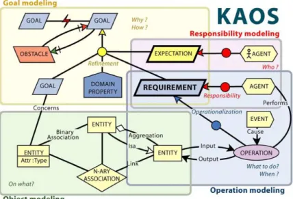
Figure 3.9: KAOS Models
of the goals, to recognize conflicts among goals, and to analyze the impact of requirements changes. Furthermore the values on a goal graph and its structural characteristics allow the analyst to estimate the quality of the resulting requirements specification, such as correctness, unambiguity, completeness etc. The estimated quality values can suggest which goals should be improved and/or refined.
3.4.4.5 ESPRIT CREWS
The ESPRIT CREWS [79] approach aims to discover requirements through a bi-directional coupling between goals and scenarios. Three characteristics of the proposed approach contribute to the achievement of this objective: First, a bidirectional goal-scenario coupling. The second characteristic of the approach is the distinction between the refinement relationship and the AND/OR relationships among goals. The third characteristic is the methodological support provided in the form of enactable guiding rules embodied in a computer software environment called L’Ecritoire. As a result, it is possible to guide the requirements elicitation process through interleaved goal modeling and scenario authoring. Here, the focus is on the discovery of goals from scenarios. The discovery process is centered around the notion of a Requirement Chunk (RC) which is a <Goal, Scenario> pair.
3.4.4.6 The Knowledge Acquistion in autOmated Specification (KAOS) Method
Kaos [55] is a methodology forREenabling analysts to build requirement models and to derive requirement documents from Kaos models. Kaos is based on goals treated at a high level of abstraction. The Kaos language is a multi-paradigm language used for modeling goals in order to specify requirements in anREprocess. It consists of several models, which are connected to each other through rules of inter-model consistency.
3.4. Approaches of Requirements Engineering
Kaos serves in building a model for the requirements which helps in describing the problem to be solved and the constraints that must be fulfilled by any solution provider. Kaos helps in: problem description by allowing to define and manipulate concepts relevant to problem description, to improve the problem analysis process by providing a systematic approach for discovering and structuring requirements, to clarify the responsibilities of all project stakeholders and to let the stakeholders communicate easily and efficiently about the requirements.
Goals are desired system properties that have been expressed by some stakeholder. Using Kaos, the analyst discovers the new system by interviewing current and future users and by analyzing the existing systems, reading the available technical documents. Kaos enables the analyst to structure the collected goals into directed, acyclic graphs so that each goal in the model (except the roots, the top most strategic goals) is typically justified by at least another goal that explains why the goal was introduced in the model and that each goal (except the leaves, the bottom goals) is refined as a collection of sub-goals describing how the refined goal can be reached. A Kaos model aggregates four complementary and interrelated views on the information system9.
– The goal model refers to the goals wished by the stakeholders involved in the informa-tion system, i.e., the owners, the users, the business managers, regulainforma-tions etc. and the requirements on the information that are needed in order to achieve these goals. – The responsibility model refers to the inventory of human and automated agents
located inside the system or belonging to its environment and to whom responsibility for achieving the requirements is assigned.
– The object model defines the problem domain in terms of domain concepts and rela-tionships over those concepts.
– The operation model defines the behavior that those agents must undertake in order to achieve or maintain the requirements for which they are responsible.
Figure3.9shows the four Kaos models.
3.4.5 Discussion
The most importantREapproaches of recent years are goal oriented. This success is due to the fact that when theGOREprocess finish its work, all the other approaches starts from there [56]. Goals concentrate on the activities before the requirements formalization [70]. Most of the other approaches ofREconcentrate on what the software should do and how to do it but not on the reasoning about the requirements. Consequently, it will be difficult afterwards to understand the requirements and to judge whether, they really capture the stake holders needs.
Traditional approaches of RE focus on the specification of the system-to-be alone and do not consider its environment, which is one of the reason of the inadequacy of these approaches when dealing with more and more complex systems. In the context of this thesis, we aim to provide an integrated approach for defining and modeling the requirements ofSAS,
for specifying these intentions [54]. Various studies [37,100,58,99] suggest that goals can be used to systematically model the requirements of aSAS.
The choice of Kaos [55] is motivated by the fact that it permits the expression of several models (goal, agent, object, behavioral models) and the relationship between them. It also provides a powerful and extensive set of concepts to specify goal models. This facilitates the design of goal hierarchies with a high level of expressiveness that can be considered at different levels of abstraction.
3.5
Conclusion
SEis concerned with all the phases of software development i.e. from software spec-ification till maintenance of the resulting software. SE engulfs different activities while a software is developed i.e. software specification, software design and implementation, software validation and software evolution. Software specification or more specifically, REis one of the most important activity ofSE. Different technical reports have shown that errors at this stage of the software development life cycle are the most costlier to be addressed in the later stages i.e. it results in resource overspending and in some cases even in the failure of software. In literature, we have different approaches ofRE. GOREapproaches have gained success due to the use of goal models where we can easily identify the stakeholders involved, resolve conflicts, assign responsibility to agents. Due to the specific needs ofSAS, we need an approach that best takes into account the uncertainty posed bySASand which must support alternative system configurations, that are provided byGOREapproaches. MDEtechniques are permeating all the fields ofSE. We take benefit ofMDEtechniques for the development of tools in order to validate our propose approach.
CHAPTER
4
Requirements Engineering &
Properties Verification of Self
Adaptive Systems
Contents
4.1 Requirements Engineering for Self Adaptive Systems . . . 34 4.1.1 Levels of Requirement Engineering for Modeling . . . 34 4.1.2 REcording of Assumptions in RE. . . 35 4.1.3 Awareness Requirements . . . 36 4.1.4 RELAX augmented with CLAIMS . . . 36 4.1.5 AutoRELAX . . . 37 4.1.6 Fuzzy Live Adaptive Goals for Self-Adaptive Systems . . . 37 4.1.7 Discussion . . . 38 4.2 Properties Verification of Self Adaptive Systems. . . 39 4.2.1 MEDISTAM-RT . . . 39 4.2.2 Timed UML and RT-LOTOS Environment . . . 39 4.2.3 UPPAAL . . . 40 4.2.4 SysML with B Specifications . . . 40 4.2.5 The OMEGA2 UML/SysML Profile . . . 41 4.2.6 IFx Toolset . . . 41 4.2.7 Discussion . . . 41 4.3 Conclusion . . . 42
![Figure 3.1: The Software Engineering Process [86]](https://thumb-eu.123doks.com/thumbv2/123doknet/14743426.755495/31.892.278.658.167.464/figure-the-software-engineering-process.webp)
![Figure 3.5: Projects Success Rates 1994 to 2009 [40]](https://thumb-eu.123doks.com/thumbv2/123doknet/14743426.755495/37.892.251.686.165.572/figure-projects-success-rates-to.webp)
![Figure 3.6: Reasons for Resource Overspend [39]](https://thumb-eu.123doks.com/thumbv2/123doknet/14743426.755495/38.892.150.699.169.455/figure-reasons-for-resource-overspend.webp)
![Figure 3.8: The Requirements Engineering Process [86]](https://thumb-eu.123doks.com/thumbv2/123doknet/14743426.755495/40.892.153.697.168.450/figure-the-requirements-engineering-process.webp)
![Figure 5.2: Relax Process [96]](https://thumb-eu.123doks.com/thumbv2/123doknet/14743426.755495/60.892.209.641.164.559/figure-relax-process.webp)
![Figure 5.5: SysML/Kaos Meta Model [36]](https://thumb-eu.123doks.com/thumbv2/123doknet/14743426.755495/65.892.194.739.168.520/figure-sysml-kaos-meta-model.webp)
![Figure 5.6: IFX Workflow [91]](https://thumb-eu.123doks.com/thumbv2/123doknet/14743426.755495/69.892.197.735.161.822/figure-ifx-workflow.webp)