HAL Id: tel-02497429
https://hal.archives-ouvertes.fr/tel-02497429
Submitted on 3 Mar 2020
HAL is a multi-disciplinary open access archive for the deposit and dissemination of sci-entific research documents, whether they are pub-lished or not. The documents may come from teaching and research institutions in France or abroad, or from public or private research centers.
L’archive ouverte pluridisciplinaire HAL, est destinée au dépôt et à la diffusion de documents scientifiques de niveau recherche, publiés ou non, émanant des établissements d’enseignement et de recherche français ou étrangers, des laboratoires publics ou privés.
Influence of mixing and curing conditions on the
characteristics and durability of soils stabilised by deep
mixing
Antoine Guimond-Barrett
To cite this version:
Antoine Guimond-Barrett. Influence of mixing and curing conditions on the characteristics and dura-bility of soils stabilised by deep mixing. Géotechnique. Université du Havre, 2013. English. �tel-02497429�
Thèse de Doctorat
en vue de l’obtention du titre de
Docteur de l’Université du Havre
Spécialité : Génie Civil
présentée par
Antoine Guimond-Barrett
Ecole Doctorale SPMII: Sciences Physiques, Mathématiques et de l'Information pour l'Ingénieur
Influence of mixing and curing conditions on the
characteristics and durability of soils stabilised by deep
mixing
Yu-Jun CUI Rapporteur
Hussein MROUEH Rapporteur
Abir AL-TABBAA Examinatrice
Sabine DARSON-BALLEUR Examinatrice
Nicolas DENIES Examinateur
Alain LE KOUBY Examinateur
Anne PANTET Directrice de thèse
Philippe REIFFSTECK Directeur de thèse
Remerciements
Je voudrais tout d'abord remercier M. Hussein MROUEH et M. Yu-Jun CUI de m'avoir fait l'honneur d'accepter d'évaluer ce travail de thèse en tant que rapporteurs.
Je remercie également Mme Abir AL-TABBAA et M. Nicolas DENIES d’avoir accepté de participer au jury de thèse en tant qu’examinateurs.
Je tiens à adresser mes sincères remerciements à Mme Anne PANTET et M. Philippe REIFFSTECK, directeurs de cette thèse, pour leur immense soutien, leur encadrement, leur disponibilité, leurs conseils. Je remercie également M. Alain LE KOUBY de son suivi continu tout au long de ce doctorat.
Ce travail est le fruit d’une étroite collaboration entre l’Ifsttar et Soletanche Bachy dans le cadre du projet de recherche Rufex. Je tiens à remercier tout particulièrement Mme Sabine DARSON-BALLEUR et M. Jean-Fançois MOSSER pour leur suivi, leur soutien, leur aide et leurs conseils pendant toute la durée de ce projet qui ont grandement contribué à améliorer ce travail.
Je voudrais également remercier l’ensemble des partenaires de Rufex pour leurs commentaires pertinents et constructifs lors des réunions de projet.
Au sein de l’Ifsttar, je tiens à remercier M. Franck GUIRADO, Mme Sonia FANELLI et M. Jean-Louis TACITA pour leur participation à la réalisation des essais en laboratoire et sur le terrain. Je remercie Mme Myriam DUC et Mme Aurélie MALOULA pour leur contribution à la partie microstructure de ce travail. Je remercie également M. Christophe CHEVALIER et M. Sébastien BURLON.
Je tiens à saluer les autres doctorant(e)s de l’Ifsttar avec qui j’ai partagé trois années intenses: Chi-Wei CHEN, Jerôme CHRISTIN, Iman HAGHIGHI, Elodie NAULEAU, Mamadou NGOM et Fabien SZYMKIEWICZ. Merci à tous !
Enfin, je ne pourrais pas finir ces remerciements sans penser à Mathilde, mes parents et ma sœur pour leur présence, leur patience et leurs encouragements qui m’ont permis de passer ces trois années dans le bonheur et la bonne humeur !
Abstract
Deep mixing is a ground improvement technique used in various offshore and on-land applications. In this method, soils are mechanically mixed in situ with a hydraulic binder using specifically designed mixing tools. Although deep mixing is used as an economical alternative with a minimum environmental impact in many projects compared to other types of foundations, the uncertainties regarding the characteristics of the soil-cement materials (“soil-mix materials”) frequently limit the application of the process. Indeed, the mechanical properties (essentially compressive strength and stiffness) of soils stabilised by deep mixing are still poorly understood and particularly difficult to control. Many factors influence the characteristics of treated soils. These factors are essentially related to the type and amount of binder, the soil conditions (soil type, moisture content), the mixing conditions and the curing conditions. The durability or long-term behaviour of soils stabilised with cement is also an important concern for the design of permanent deep mixing structures.
The aim of this research, part of the French RUFEX research project, is to reach a better understanding of the properties of soil-mix materials produced in situ by wet deep mixing. Two main objectives are defined. The first objective is to evaluate and compare the strength and deformation characteristics of soils treated in the laboratory and in situ. Different soils were mixed with cement in the laboratory and tested. Additionally, the characteristics of soils treated in situ were determined on specimens taken from four different test sites where soil-cement columns were installed by Soletanche Bachy. The second objective is to analyse potential factors impacting the durability of treated soils. The presence of potential deleterious chemical compounds (calcium sulfate, sodium chloride and diesel) and the effects of drying are the two potential degradation mechanisms studied in order to assess the durability of cement-mixed soils.
Despite relatively large scatter, the results from this study highlight distinctive trends in terms of relations between strength (compressive and tensile) and stiffness (static and dynamic) which are specific to soil-mix materials. The effects of different mixing and curing conditions on the characteristics of treated soils are identified. The data gathered in this research shows that it is possible to define a standardised framework for the assessment of the durability of soils stabilised by deep mixing based on potential durability indicators. The direct correlation between potential indicators and controllable factors (such as binder and water contents) point to the possibility of optimising the durability related properties of soil-mix materials within the boundaries imposed by the soil conditions on site. Potential durability classes based on porosity accessible to water are proposed to compare different soil-cement mixtures.
Résumé
Le deep mixing est une technique d'amélioration de sols utilisée dans diverses applications sur terre et en mer. La méthode consiste à mélanger mécaniquement les sols en place avec un liant hydraulique à l’aide d’outils de malaxage spécifiques. Dans de nombreux projets, le deep mixing est utilisé comme une alternative économique avec un impact minimal sur l'environnement comparée à d’autres solutions de fondations. Cependant, les incertitudes concernant les caractéristiques des matériaux produits ("matériaux soil-mix") pénalisent fortement le procédé. En effet, les propriétés mécaniques (en particulier la résistance à la compression et le module de déformation) des sols traités par deep mixing sont encore mal connues et particulièrement difficiles à contrôler. De nombreux facteurs influencent les caractéristiques des sols traités. Ces facteurs sont essentiellement liés à la nature et à la quantité de liant, aux caractéristiques du sol (type de sol, la teneur en eau), aux conditions de mélange et aux conditions de cure. La durabilité ou le comportement à long-terme des sols traités avec du ciment est également une préoccupation importante pour la conception d’ouvrages permanents.
Les principaux objectifs de ce travail, qui s’intègre dans le projet de recherche RUFEX, sont de parvenir à une meilleure connaissance des propriétés mécaniques des matériaux sol-ciment produits in situ par deep mixing. Deux axes principaux sont définis. Le premier objectif est de comparer les caractéristiques de résistance et de déformation des sols traités en laboratoire et in situ. Différents sols ont été mélangés avec du ciment en laboratoire. Les caractéristiques de sols traités in situ ont été déterminées sur des éprouvettes prélevées sur quatre sites expérimentaux où des colonnes de sol-ciment ont été installées par Soletanche Bachy. Le second objectif est d'évaluer l’impact de certains facteurs susceptibles d'influer sur la durabilité des sols traités. La présence de composés chimiques potentiellement perturbateurs (sulfate de calcium, chlorure de sodium et diesel) et les effets du séchage sont les deux mécanismes de dégradation potentiels étudiés afin d'évaluer la durabilité des sols traités. Malgré une certaine dispersion, les résultats de cette étude mettent clairement en évidence des relations entre la résistance (en compression et en traction) et la rigidité (modules statique et dynamique) spécifiques aux matériaux soil-mix. Les effets de différentes conditions de mélange et de cure sur les caractéristiques des sols traités sont identifiés. Les données accumulées dans cette recherche montrent qu'il est possible de définir, à partir de différents indicateurs, un cadre général pour l'évaluation de la durabilité des sols traités par deep mixing. La corrélation directe entre certains indicateurs potentiels et les paramètres de mise en oeuvre (tels que le dosage en ciment et la teneur en eau) suggère qu'il est possible d'optimiser les propriétés des matériaux soil-mix dans les limites imposées par les conditions géologiques du site. Des classes de durabilité potentielle basées sur la porosité accessible à l'eau sont proposées pour comparer différents mélanges sol-ciment.
Table of contents
REMERCIEMENTS ... I ABSTRACT ... III RESUME ... IV TABLE OF CONTENTS ... V NOMENCLATURE ... XI GENERAL INTRODUCTION ... 1CHAPTER 1. THE DEEP MIXING METHOD – OVERVIEW ... 5
1.1 INTRODUCTION ... 5
1.2 THE DEEP MIXING METHOD ... 5
1.2.1 Classification ... 5
1.2.2 Equipment and execution ... 7
1.2.2.1 Dry mixing methods ... 7
1.2.2.2 Wet mixing methods ... 10
1.2.2.3 Other methods ... 13
1.2.2.4 Conclusions ... 15
1.2.3 Applications, advantages and limitations of deep mixing ... 15
1.2.3.1 Applications ... 15
1.2.3.2 Patterns ... 15
1.2.3.3 Advantages and limitations ... 16
1.2.4 Conclusions ... 17
1.3 ENGINEERING PROPERTIES OF SOILS STABILISED WITH CEMENT ... 17
1.3.1 Parameters required for design ... 17
1.3.2 Methods used to determine the properties of stabilised soils ... 17
1.3.2.1 Sampling and laboratory testing ... 18
1.3.2.2 In situ testing ... 19
1.3.2.3 Execution parameters ... 20
1.3.3 Types of cement and basic mechanisms involved in soil treatment ... 20
1.3.4 Mechanical characteristics and engineering properties of soil-mix materials .... 21
1.3.4.1 Density... 22
1.3.4.2 Unconfined compression strength... 22
1.3.4.3 Tensile strength ... 24
1.3.4.4 Deformation modulus ... 25
1.3.4.5 Permeability ... 29
1.3.5 Important factors affecting the characteristics of stabilised soils ... 29
1.3.5.1 Factors related to the binder... 30
1.3.5.2 Factors related to soil characteristics ... 32
1.3.5.3 Factors associated with the mixing conditions... 33
1.3.5.4 Factors related to the curing conditions ... 38
1.3.6 Parameters used for design ... 39
1.3.7 Conclusions ... 40
1.4 DURABILITY OF STABILISED SOILS ... 41
1.4.1 Long-term performance of soil mixing structures ... 41
1.4.1.1 Increase in mechanical properties over time ... 41
1.4.1.2 Long-term deterioration of stabilised soils ... 44
1.4.2.3 Sulfate attack ... 48
1.4.2.4 Effects of exposure to chlorides ... 50
1.4.2.5 Effects of organic contaminants ... 52
1.4.3 Conclusions ... 52
1.5 SUMMARY AND OBJECTIVES OF THIS STUDY ... 53
CHAPTER 2. MATERIALS, METHODS AND EXPERIMENTAL PROGRAMS .... 55
2.1 INTRODUCTION ... 55
2.2 SOILS AND BINDERS ... 55
2.2.1 Artificial soils ... 55
2.2.2 Natural soils ... 56
2.2.3 Binders ... 57
2.3 SPECIMEN PREPARATION PROCEDURES AND EXPERIMENTAL PROGRAM FOR FRESH MATERIALS ... 57
2.3.1 Specimen preparation ... 57
2.3.2 Experimental program for fresh material ... 57
2.3.3 Testing apparatus and procedure ... 58
2.4 SPECIMEN PREPARATION PROCEDURES AND EXPERIMENTAL PROGRAMS FOR HARDENED MATERIALS ... 59
2.4.1 Specimen preparation and sampling ... 59
2.4.1.1 Specimen preparation for soils mixed in the laboratory... 59
2.4.1.2 Sampling and specimen preparation for soils mixed in situ ... 59
2.4.2 Experimental programs for soils mixed in the laboratory ... 61
2.4.2.1 Experimental program to investigate the properties of soils stabilised in the laboratory ... 61
2.4.2.2 Experimental program to investigate the effects of chemical compounds ... 62
2.4.2.3 Experimental program to investigate the effects of drying and wetting/drying cycles ... 63
2.5 LABORATORY TESTING PROCEDURES ... 65
2.5.1 Mechanical parameters derived from destructive tests ... 65
2.5.1.1 Unconfined compressive strength tests and static deformation modulus measurements ... 66
2.5.1.2 Splitting tensile strength tests ... 67
2.5.2 Mechanical parameters derived from non-destructive tests ... 67
2.5.2.1 Ultrasonic wave velocity measurements ... 67
2.5.2.2 Free-free resonance tests (FFR tests) ... 69
2.5.3 Measurements of hydraulic properties ... 70
2.5.3.1 Porosity accessible to water ... 70
2.5.3.2 Permeability ... 70
2.5.4 Microstructural investigations ... 71
2.5.4.1 X-Ray diffraction analysis ... 71
2.5.4.2 Scanning electron microscopy ... 71
2.5.4.3 Pore size distribution by mercury intrusion porosimetry (MIP) ... 71
CHAPTER 3. MECHANICAL PROPERTIES OF SOILS STABILISED WITH CEMENT IN THE LABORATORY ... 73
3.1 INTRODUCTION ... 73
3.2 EXPERIMENTAL RESULTS AND ANALYSES ON FRESH MATERIALS ... 73
3.2.1 Flow curves of kaolin ... 73
3.2.2 Flow curves of cement slurries ... 74
3.2.3 Flow curves of clay-cement mixes ... 75
3.2.4 Discussion ... 76
3.2.5 Conclusions ... 77
3.3 EXPERIMENTAL RESULTS AND ANALYSES ON HARDENED MATERIALS ... 77
3.3.1 Density, moisture content and porosity accessible to water ... 77
3.3.2.1 Development of unconfined compressive strength with time ... 80
3.3.2.2 Prediction of strength development based on parameters obtained after short curing times ... 87
3.3.3 Static deformation modulus ... 91
3.3.3.1 Loading procedures ... 91
3.3.3.2 Stiffness-strain curves for soils stabilised in the laboratory with cement ... 93
3.3.3.3 Strength – static stiffness relations for soils stabilised in the laboratory ... 94
3.3.4 Dynamic modulus of elasticity ... 96
3.3.4.1 Choice of Poisson’s ratio ... 96
3.3.4.2 Increase in dynamic modulus with time ... 97
3.3.4.3 Prediction of stiffness development based on parameters obtained after short curing times ... 100
3.3.4.4 Summary for the prediction of strength and stiffness growth ... 102
3.3.4.5 Strength – dynamic stiffness relations for soils stabilised in the laboratory ... 103
3.3.4.6 Rigidity and degree of non-linearity for soils stabilised in the laboratory ... 110
3.3.5 Indirect tensile strength ... 113
3.3.6 Summary of results on hardened materials ... 113
3.4 CONCLUSIONS ... 114
CHAPTER 4. CHARACTERISTICS OF SOILS STABILISED IN SITU BY DEEP MIXING……… ... 115
4.1 INTRODUCTION ... 115
4.2 VERNOUILLET TEST SITE ... 115
4.2.1 Site location ... 115
4.2.2 Site investigation ... 116
4.2.3 Ground conditions ... 117
4.2.4 Field trial – Outline of column installation works ... 117
4.2.4.1 Soil mixing equipment and column installation procedure ... 117
4.2.4.2 Quality control during construction ... 119
4.2.4.3 Column excavation ... 123
4.3 OTHER SITES ... 124
4.4 RESULTS OF LABORATORY TESTS PERFORMED ON SPECIMENS OF IN SITU DEEP MIXED SOILS… ... 125
4.4.1 Moisture content ... 125
4.4.2 Wet density ... 127
4.4.3 Porosity accessible to water ... 128
4.4.4 Unconfined compressive strength ... 129
4.4.5 Static deformation modulus ... 136
4.4.5.1 Static stiffness in columns from Vernouillet ... 136
4.4.5.2 Strength – static stiffness relations for soils stabilised in situ by deep mixing ... 138
4.4.6 Ultrasonic wave velocity ... 139
4.4.6.1 Wave velocities in columns from Vernouillet ... 139
4.4.6.2 Relation between wave velocity and strength ... 141
4.4.6.3 Relation between wave velocity and static modulus ... 141
4.4.7 Dynamic modulus of soils stabilised in situ by deep mixing ... 142
4.4.7.1 Dynamic modulus in columns from Vernouillet ... 142
4.4.7.2 Relation between dynamic modulus and strength ... 144
4.4.8 Shear wave velocity and small strain shear modulus ... 147
4.4.8.1 Wave velocities from resonance testing... 147
4.4.8.2 Dynamic shear modulus and Poisson’s ratio ... 149
4.4.8.3 Correlation with density ... 150
4.4.8.4 Relation with static deformation modulus ... 151
4.4.8.5 Relation with porosity ... 151
4.4.9 Indirect tensile strength ... 152
4.5 IN SITU LOAD TEST –INPUT PARAMETERS FOR NUMERICAL ANALYSES ... 153
4.5.1 Load test procedure ... 153
4.6 DISCUSSION –EFFECTS OF MIXING CONDITIONS AND SAMPLING METHOD... 156
4.6.1 Comparison between field and laboratory specimens ... 156
4.6.2 Influence of soil type and sampling method ... 158
4.7 CONCLUSIONS ... 159
CHAPTER 5. DURABILITY OF STABILISED SOILS ... 163
5.1 EFFECTS OF THE PRESENCE OF POTENTIAL DELETERIOUS CHEMICAL COMPOUNDS ON THE LONG-TERM MECHANICAL PROPERTIES OF STABILISED SOILS ... 163
5.1.1 Introduction ... 163
5.1.2 Fontainebleau sand treated with CEM I ... 163
5.1.2.1 Effect on unconfined compressive strength and static modulus ... 163
5.1.2.2 Effect on ultrasonic wave velocity and dynamic modulus ... 165
5.1.2.3 Effect on indirect tensile strength ... 167
5.1.2.4 Effect on porosity ... 167
5.1.2.5 Scanning electron microscopy ... 169
5.1.2.6 Conclusions ... 171
5.1.3 Fontainebleau sand treated with CEM III ... 171
5.1.3.1 Effects on unconfined compressive strength and static modulus ... 171
5.1.3.2 Effects on ultrasonic wave velocity and dynamic modulus ... 173
5.1.3.3 Effects on indirect tensile strength ... 175
5.1.3.4 Volumetric swelling ... 175
5.1.3.5 X-ray diffraction ... 176
5.1.3.6 Effects on porosity and permeability ... 176
5.1.3.7 Scanning electron microscopy ... 179
5.1.4 Artificial silt treated with CEM III ... 181
5.1.4.1 Effects on unconfined compressive strength and static modulus ... 181
5.1.4.2 Effects on ultrasonic wave velocity and dynamic modulus ... 182
5.1.4.3 Effects on indirect tensile strength ... 184
5.1.4.4 X-ray diffraction ... 185
5.1.4.5 Effects on porosity and permeability ... 185
5.1.4.6 Scanning electron microscopy ... 187
5.1.1 Summary of results ... 187
5.1.2 Conclusions on the effects of potential deleterious compounds ... 190
5.2 INFLUENCE OF DRYING ON THE STIFFNESS AND STRENGTH OF STABILISED SOILS ... 191
5.2.1 Introduction ... 191
5.2.2 Small strain shear modulus of specimens immersed in water ... 191
5.2.3 Effects of cyclic wetting and drying on small strain shear modulus ... 194
5.2.4 Effects of continuous drying on small strain shear modulus ... 196
5.2.5 Effects of curing conditions on strength and static stiffness ... 198
5.2.6 Carbonation ... 201
5.2.7 Discussion ... 203
5.2.8 Conclusions on the influence of drying ... 206
5.3 CONCLUSIONS ... 207
GENERAL DISCUSSION – DURABILITY OF SOIL-MIX MATERIALS ... 209
GENERAL CONCLUSIONS ... 215
REFERENCES ... 221
APPENDIX A ... 237
APPENDIX B ... 243
APPENDIX D ... 257 APPENDIX E ... 261
Nomenclature
C cement content (% and kg/m3) c cohesion (kPa)
Cu Undrained shear strength (kPa) C/W cement-water ratio
E0 dynamic modulus (MPa)
E0,t dynamic modulus at curing time t (MPa)
E50 static secant deformation modulus at 50% of maximum stress (MPa)
Fs safety factor
fc,d strength used for the design
fp resonant frequency for compression waves (Hz)
fs resonant frequency for shear waves (Hz)
G0 small strain shear modulus (MPa)
G0,t small strain shear modulus at curing time t (MPa)
i hydraulic gradient k permeability (m/s)
k7 empirical parameter used to predict the shear modulus growth based on 7-day data
L length (m)
M number of mixing blades
Nd rotation speed of the mixing tool during penetration (rev/min)
Nu rotation speed of the mixing tool during retrieval (rev/min)
PI plasticity index (%)
pl* Menard pressuremeter limit pressure (MPa)
q7 empirical parameter used to predict modulus growth based on 7-day data
q28 empirical parameter used to predict modulus growth based on 28-day data
qd dynamic penetration resistance (MPa)
qit indirect tensile strength (MPa)
qu unconfined compressive strength (MPa)
qu,t unconfined compressive strength at curing time t (MPa)
s7 empirical parameter used to predict strength growth based on 7-day data
s28 empirical parameter used to predict strength growth based on 28-day data
T blade rotation number (rotation/m) t curing time (days) or travel time (s) V wave velocity (m/s)
Vd penetration velocity (m/min)
Vp compression wave velocity (m/s)
Vs shear wave velocity (m/s)
Vu speed during withdrawal (m/min)
w moisture content (%) wL liquid limit (%)
empirical parameter used to calculate the design strength empirical factor used to predict strength and modulus growth angle of friction (rad/°)
Poisson’s ratio 0 yield stress (Pa)
General Introduction
The foundations of many old railway lines in Europe need to be reinforced as they no longer meet the requirements of modern traffic. Deterioration of the platform is often linked to insufficient drainage causing a reduction in the mechanical properties of the subgrade. Railway structures lying on damaged platforms may present problems such as reduced stability, settlements, and extensive vibrations (Eurosoilstab, 2002). In all these cases, remediation works most often involve increasing the stiffness of the subsoil.
Classic platform reinforcement works are time-consuming and require the temporary removal of the tracks with ensuing traffic interruptions. Moreover, these types of works are expensive and their production rates are low. Optimising track maintenance operations and reducing the impact on traffic is an important issue in railway network management.
Jet grouting, a ground improvement process in which high speed jets of grout are used to cut the soil and form columns or panels (Chu et al., 2009), has been tested to reinforce railway platforms while keeping the tracks and sleepers in place. This method has its advantages in terms of stiffness increase but has proved to be unsuitable due to the generation of significant amounts of spoil which pollute the ballast with cement.
There is currently no platform foundation reinforcement method compatible with the requirements of maintaining traffic (working under low catenaries without removing the tracks and with minimal impact on the ballast).
Deep mixing is a general term for a large number of techniques in which binding agents are dispersed within the soil either in powder (dry method) or slurry form (wet method) using specially designed mixing tools. The hydraulic binders are injected at low pressures and mechanically mixed with the soil thus limiting the volume of spoil. Hence, deep mixing could be used to reinforce the foundations of existing railway platforms.
The dry soil mixing method was tested in Scandinavia on many new railway construction projects in soft soils (Baker, 2000; Holm et al., 2002; Alen et al., 2005; Olsson et al., 2008). In the United Kingdom, the wet method was tested on an existing railway line (Konstantelias et al., 2002).
In France, the first field trial carried out to assess the effects of vertical soil-cement columns constructed with the wet soil mixing method was undertaken in the European research project Innotrack (INNOvative TRACK systems; Ekberg and Paulsson, 2010; Le Kouby et al., 2008). Field tests were conducted on an existing LGV railway in the Picardie region. Preliminary results from these tests were promising as they showed that the wet mixing method could meet the requirements for traffic maintenance.
Following Innotrack, the French RUFEX research project, launched in 2010, focuses on the reinforcement and re-use of existing railway track and building foundations by deep soil mixing. Its main objectives are to increase knowledge and understanding of the behaviour of such structures by working on both technological (tools and materials) and design aspects of wet deep soil mixing.
As part of RUFEX, the present experimental work focuses on the properties of the soil-cement materials (“soil-mix materials”) produced in situ by deep mixing.
Originally, the primary application of deep mixing was ground improvement to enhance the stability and reduce the settlements of embankments on very soft cohesive soils. The objective was to produce stabilised soils that have higher strength, lower permeability and lower compressibility than the original soils. Nowadays, there is increasing interest in the use of this technique not only for soil stabilisation but also to construct temporary and permanent foundation/structural (load bearing) elements and excavation retaining walls (Denies et al., 2012a; Shao et al., 2005). The properties and types of soils encountered for these new applications of deep mixing differ greatly from those found in soft soil stabilisation projects. For this reason, the results from previous research may not necessarily apply to these new materials.
The scope of this research extends beyond the reinforcement of railway platforms. This study on the properties of deep-mixed soils covers general geotechnical works such as foundations and retaining walls.
The mechanical properties of soil-cement mixtures produced by deep mixing lie between those of soil and concrete. The parameters required for design vary depending on the projects and proposed applications. In general, strength but also reliable stiffness characteristics are essential as they significantly affect the distribution of loads between soil mixing elements and the surrounding soil, thus controlling the settlements. Stiffness values are the main input parameters in numerical analyses carried out to design soil mixing structures.
Many factors influence the strength and compressibility characteristics of treated soils. These factors are essentially related to the type and amount of binder, the soil conditions, the mixing conditions and the curing conditions. The engineering properties are highly variable and difficult to control.
Soils are stabilised in the laboratory to evaluate the effects of different binder contents, binder types and water/binder ratios on the mechanical properties of treated soils. Previous research carried out at IFSTTAR focused mainly on the mechanical properties of soils treated in the laboratory (Szymkiewicz, 2011). A large number of soils were mixed with different quantities of cement and water. The results provide interesting information regarding the influence of particle size distribution, clay content and dosage on the strength of soil-mix materials. However, the relation between field and laboratory properties remains unclear. The mixing conditions on site are different from laboratory procedures. The strength and deformation properties determined in situ may differ considerably from those measured on laboratory samples. In addition, the methods used to sample soils treated in situ may influence the results.
The durability or long-term behaviour of soils stabilised with cement is also an important concern for the design of permanent deep mixing structures. In the field, the cement hydration process and hardening of the material take place in various environmental conditions that may modify the effects of the binder. Depending on the application, treated soils may be subjected to different curing conditions which could considerably alter the mechanical properties. Although deep mixing is often used as an economical alternative with a minimum environmental impact in many projects compared to other types of foundations, the uncertainties regarding the characteristics of the material often seriously penalise the process. These uncertainties are usually compensated by preliminary trials and conservative designs which ultimately (and often unnecessarily) increase the construction costs.
The aim of this research is to contribute to the reduction of some uncertainties regarding in situ soil-mix materials. The objectives are to:
- to reach a better understanding of the engineering properties required for design. The general approach followed consists in analysing the mechanical properties of different soils stabilised in the laboratory and to compare the results with the characteristics of soils treated in situ by deep mixing.
- to assess the impact of some potential degradation mechanisms on the durability of treated soils. Artificial soils treated in controlled laboratory conditions are preferred to field specimens of potentially variable characteristics to study factors related to durability.
Organisation of the thesis
The thesis is organised in five chapters.
The first chapter provides a non-exhaustive overview of previously published work on soil-mix materials. Firstly, the different techniques used to construct soil soil-mixing elements are presented. The engineering parameters required for design and the methods used in practice to determine these parameters are outlined. Current knowledge of the engineering properties of soil-mix materials is reviewed and the factors affecting the characteristics of treated soils are examined. Finally, the durability of treated soils is addressed with emphasis on the long-term behaviour of existing structures and potential degradation mechanisms. Research needs are highlighted and precise objectives are defined.
The second chapter details the different materials, experimental techniques and experimental programs followed in this research. The characteristics of the soils and binders used in this study are given. The procedures used to prepare specimens of treated soils in the laboratory are explained. The sampling methods employed to obtain specimens of soils mixed in situ by deep mixing are described. The various laboratory testing procedures utilised to determine the properties of soil-mix materials are presented. The experimental programs followed to assess
The results of tests carried out to evaluate the mechanical behaviour of soils mixed in the laboratory with cement are presented in the third chapter. The study is performed on soil-mix materials in the fresh state immediately after mixing and in the hardened state. Special attention is paid to the relations between strength and stiffness.
The properties of soils stabilised in the laboratory are compared with those of soils treated in situ in the fourth chapter. The soils mixed in situ were taken from test sites where soil-cement columns were installed by Soletanche Bachy. The effects of mixing conditions and sampling method are examined. The similarities and discrepancies between laboratory and field samples are highlighted. The results are discussed with respect to the design of soil mixing elements.
In the fifth chapter, the durability of soil-mix materials against different potential degradation mechanisms is assessed through tests performed on specimens treated in the laboratory. The long-term effects of these degradation mechanisms on the physical and mechanical properties are studied for curing times of up to 360 days.
The thesis closes on a general discussion on the possibility of optimising the durability-related properties of soil-mix materials. General conclusions are drawn in an attempt to provide useful recommendations for future deep mixing projects.
Chapter 1. The Deep Mixing Method – overview
1.1 Introduction
This chapter is a non-exhaustive overview of previously published work on the deep mixing method and soil-mix materials. The purpose of this review is to identifiy research needs in order to specify the objectives of this research. The chapter is organised in 3 main sections:
- In section 1.2, the different construction techniques, equipment and various applications of deep mixing are presented.
- The engineering properties and some factors affecting the characteristics of treated soils are examined in section 1.3.
- Finally, the durability of treated soils is addressed in section 1.4. Reported long-term behaviour of existing structures and potential degradation mechanisms are reviewed.
1.2 The Deep Mixing Method
1.2.1 Classification
Laboratory and field research started on deep mixing technology using dry and wet binders in the mid-1960s in Sweden at the Swedish Geotechnical Institute and in Japan at the Port and Harbour Research Institute. The aim of this research was to develop a new method to improve the properties of soft soils (Holm, 2000). The classification adopted by the Ground Improvement Technical Committee 211 of the International Society for Soil Mechanics and Geotechnical Engineering defines deep mixing as a ground improvement method with grouting type admixtures (Table 1-1 after Chu et al., 2009).
Ground improvement with grouting type admixtures
1. Particulate grouting
Grout granular soil or cavities or fissures in soil or rock by injecting cement or other particulate grouts to either increase the strength or reduce the permeability of soil or ground.
2. Chemical grouting
Solutions of two or more chemicals react in soil pores to form a gel or a solid precipitate to either increase the strength or reduce the permeability of soil or ground.
3. Mixing methods (including premixing or deep mixing)
Treat the weak soil by mixing it with cement, lime, or other binders in-situ using a mixing machine or before placement
4. Jet grouting High speed jets at depth erode the soil and inject grout to form columns or panels
5. Compaction grouting
Very stiff, mortar-like grout is injected into discrete soil zones and remains in a homogeneous mass so as to densify loose soil or lift settled ground.
6. Compensation grouting
Medium to high viscosity particulate suspension is injected into the ground between a subsurface excavation and a structure in order to negate or reduce settlement of the structure due to on-going excavation.
Several classification systems for the different technologies and equipments used in deep mixing have been proposed (FHWA, 2000; CDIT, 2002 and AFNOR, 2005). The classification by Topolnicki (2004) is based on three parameters (Figure 1-1):
- the form in which the binder is introduced into the soil (either wet or dry),
- the method used to mix the binder (by mechanical mixing with the tool, by high pressure injection (jet) or both (mechanical + jet),
- the location where mixing occurs (at the end or along the shaft).
The large number of techniques identified in Figure 1-1 can be explained in part by the necessity to adapt to local geological conditions and by the variety of projects and applications.
Figure 1-1 General classification of in situ soil mixing based on (a) binder form, (b) mixing principle and (c) location of mixing action, with selected examples of methods developed in various countries
(Topolnicki, 2004).
The main differences between deep mixing and soil treatment for the construction of fills and capping layers are summarised in Table 1-2. No compaction is performed during the
construction of deep mixing elements; the soil-binder mixtures must be sufficiently fluid to be self-compacting.
Deep mixing Soil treatment for earthworks
Excavation Mixing is performed in situ on intact
soils, No previous excavation
Soil are excavated before treatment, Mixing is performed on remoulded soils
Depth Mixing is carried out at depth Mixing is carried out at the surface
Form of binder Dry powder or slurry Dry powder
Dosage
The quantities of binder used in deep mixing projects are generally higher
than for fills and capping layers (usually more than 10 % by mass)
Usually between 1 and 7 % by mass
Compaction
No compaction is performed, the soil-binder mixtures must be sufficiently
fluid to be self-compacting
Treatment is carried out on soils of relatively low moisture content to facilitate compaction
Table 1-2 Main differences between deep mixing and soil treatment for earthworks.
Currently, the majority of soil mixing works involve the construction of column-type elements. However, other techniques are used to construct blocks or panels. The following paragraphs describe the equipment and execution processes used in the main types of column-construction techniques. The equipment used to install blocks or panels are also briefly presented.
1.2.2 Equipment and execution
1.2.2.1 Dry mixing methods
For the dry mixing method, column construction usually starts by penetrating the mixing tool down to the target depth. The mixing tool is then lifted back up to the surface. The binder in powder form is injected during the withdrawal phase. The rotation of the mixing tool destructures the soil during penetration and mixes the soil and binder during withdrawal (Eurosoilstab, 2002).
The two main dry mixing techniques are the Scandinavian method (lime-cement columns) and the Japanese method (Dry Jet Mixing).
1.2.2.1.1 Scandinavian method: lime-cement columns
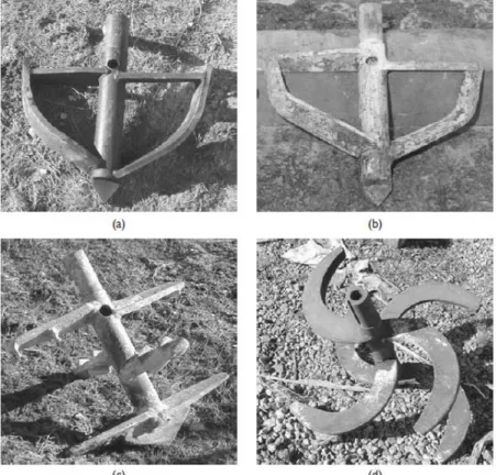
Lime and lime-cement columns are commonly used in Scandinavia to stabilise clays and silts as well as organic soils (Broms, 2004). The mixing machines generally have only one mixing shaft. The Scandinavian dry mixing method is mostly carried out in soft to very soft soils with undrained shear strengths lower than approximately 50 kPa. Typical mixing tools are shown in Figure 1-3. The injection outlet hole is located on the central shaft above the lower mixing blades to allow mixing during the lifting of the tool (Topolnicki, 2004). Columns can be installed to depths of about 25 m. The diameter of the columns is typically between 0.6 and 1.0 m. Columns can be inclined at an angle of up to 70° (AFNOR, 2005). The tool rotation speeds and withdrawal rates vary depending on geological conditions and projects. The penetration speed is in general close to 2 to 3 m per minute. Withdrawal of the tool is often carried out at 15 to 25 mm per rotation with 150 to 180 rotations per minute (FHWA, 2000).
Figure 1-3 Typical mixing tools used for the Scandinavian dry mixing method (Topolnicki, 2004).
Initially, lime was the most frequently used binder. Currently, columns are constructed using mixtures of lime and cement (Åhnberg and Johansson, 2005). The mixing energy required for the production of a column depends on the types of soil and binder, and the amount of binder. It has been noticed that the use of cement requires more energy than mixing lime alone (AFNOR, 2005). Lime contents used to treat inorganic soft clays vary between 70 to 90 kg/m3
(Broms, 2004). More generally, 80 to 150 kg of binder per cubic meter of soil are injected into the columns. The compressive strength of treated soils by the Scandinavian method is often between 0.2 and 0.5 MPa (FHWA, 2000).
Stabilised soil columns constructed by the Scandinavian method are semi-rigid. They interact with the surrounding untreated soil to form a composite system of improved ground (Holm, 1999). The permeability of the treated soils is often substantially greater than that of the initial clayey ground (Broms, 1999). Therefore the columns may also act as vertical drains.
1.2.2.1.2 Japanese method: Dry Jet Mixing (DJM)
In Japan, many techniques have been developed for the treatment of soils by the dry mixing method. The main technique is named Dry Jet Mixing (DJM). DJM rigs can be equipped with one or two shafts. The diameter of the mixing tools can reach up to 1 m. Stabilised soil columns may be installed down to depths of 16 to 33 m. The binder is injected during the withdrawal of the tool as in the Scandinavian method, but the injection can also be carried out during the penetration phase (AFNOR, 2005). The standard mixing tool is generally composed of two levels of horizontal blades (Figure 1-4). The binder outlet holes are located above and below these blades. DJM is used in soft clays with maximum shear strengths of 70 kPa and in sands with SPT blow counts below 15 (Terashi, 2003). The tool penetration speeds are typically between 1 and 1.5 m per minute. The uplift rate is usually slower from 0.7 to 0.9 m/min (Topolnicki, 2004). The rotational speed of the tool is relatively low between 24 and 32 rpm.
Figure 1-4 Typical mixing tool used for DJM (Topolnicki, 2004).
The binder used in DJM is mainly Portland cement (Porbaha, 1998) with dosages ranging from 100 to 400 kg/m3 (Bruce et al., 1999). The compressive strengths of treated soils by the Japanese method greatly vary depending on soil type but are generally close to 1 MPa (FHWA, 2000).
1.2.2.1.3 Comparison
The following table summarises and compares the main features of Scandinavian and Japanese methods of dry soil mixing.
Larger diameter columns can be executed to greater depths with the DJM equipment. The amount of binder injected in the columns is higher for DJM. The column installation parameters (penetration, withdrawal and rotation speeds) are approximately 2 to 3 times faster for the Scandinavian technique. However, by combining these parameters, both methods have comparable uplift rates (in mm per rotation). Blade rotation numbers (tool rotations per meter of column) are similar for both techniques.
The main difference between the Scandinavian technique and the Japanese technique is related to the parameter which is assumed to be most important to control the mixing process. In the Scandinavian method, rotation speed of the tool is seen as the major controlling factor whereas for DJM, the (relatively slow) translational speed of the mixing tool is deemed to be most important in the mixing process.
Scandinavian method Japanese method
Number of columns 1 1 or 2
Diameter of mixing tool 0.4 m to 1.0 m 0.8 m to 1.3 m
Maximum depth of mixing 25 m 33 m
Position of binder outlet hole Above mixing blades Below mixing blades
Penetration rate 2.0 m/min to 6.0 m/min 1.0 m/min to 1.5 m/min
Withdrawal rate 1.5 m/min to 6.0 m/min 0.7 m/min to 0.9 m/min
Rotation speed of mixing
blades 150 to 180 rpm 24 to 32 rpm
Blade rotation number 150 to 500 per m ≥ 274 per m
Quantity of binder 180 to 150 kg/m3 100 to 400 kg/m3
Withdrawal rate per tool
rotation 10 to 30 mm/rotation 10 to 35 mm/rotation
Binder Injection Generally during withdrawal Penetration and/or withdrawal
Table 1-3 Main features of the Scandinavian and Japanese methods of dry soil mixing (modified after AFNOR, 2005).
1.2.2.2 Wet mixing methods
In the wet mixing method, the hydraulic binder is mixed with water to form a slurry before it is injected into the soil. The slurry is delivered during penetration and/or withdrawal of the mixing tool. The hydraulic binder used is generally cement. The grouts are characterised by a cement-water ratio (C/W), i.e. the ratio between the mass of dry cement C and the mass of water W. The C/W ratio can be between 0.5 and 2.5, but it generally varies between 0.8 and 1.2 for most soil mixing techniques. The values of C/W are in general lower for the treatment of clays and silts than for sands and gravel because larger amounts of water are necessary to treat fine grained soils (FHWA, 2000). The addition of grout into soil normally causes the production of spoil which returns to the surface (Eurosoilstab, 2002).
1.2.2.2.1 Japanese method: Cement Deep Mixing (CDM)
In Japan, the wet soil mixing method is used both on land and offshore (CDIT, 2002). The main technique is called Cement Deep Mixing (CDM). On land, the machines are equipped with 1 to 4 shafts. The mixing tools consist of several levels of blades (Figure 1-5).
The diameter of the mixing tool is generally close to 1 m. Columns can be installed down to approximately 40 meters (Yano et al., 1996). The binder is usually cement (FHWA, 2000). Slurries have W/C ratios between 0.6 and 1.3 for binder contents between 70 and 300 kg per cubic meter of soil (Topolnicki, 2004). The tool penetration speed generally lies between 0.5 and 2 m per minute and the withdrawal speed between 1 and 2 m per minute. The compressive strengths obtained on soils treated by CDM are generally between 0.5 and 4 MPa (FHWA, 2000).
Figure 1-5 Equipment used for CDM (Topolnicki, 2004).
1.2.2.2.2 European methods
The binder used in European methods of deep mixing is generally cement. An example of a wet mixing method used in Europe is the CVR C-mix® from Belgium. The tool rotation speed is about 100 rpm. Depending on the soil conditions, the slurry (W/C ratios between 0.6 and 0.8) is injected to add approximately 350 and 450 kg of dry binder per cubic meter of soil. As in most wet mixing techniques, the binder partly (between 0 and 30 %) returns to the surface as spoil. The resulting columns have diameters between 0.43 and 1.03 m (Denies et al., 2012a). The strengths of soils treated with this method are relatively high, in general between 2 and 10 MPa (Ganne et al., 2010).
As mentioned in the introduction, the first field trial carried out to evaluate the effects of vertical soil-cement columns constructed using the wet soil mixing method to reinforce an existing railway platform was undertaken in the European research project Innotrack (INNOvative TRACK systems) (Ekberg and Paulsson, 2010; Le Kouby et al., 2008). Field tests were conducted on an existing LGV railway using a spreadable mixing tool named Springsol developed by Soletanche Bachy.
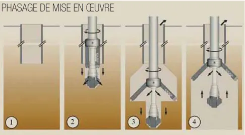
Figure 1-6 Installation procedure for columns using the Springsol tool developed by Soletanche Bachy (Mosser and Mathieu, 2011).
The installation procedure for columns constructed under existing tracks using the Springsol tool is as follows (Figure 1-6):
- a steel casing placed between the sleepers is driven through the ballast to the desired depth (n°1),
- the Springsol tool is lodged inside the casing (n°2). Once it reaches the end of the casing and penetrates the underlying soil, the blades spread out under the action of springs,
- the column is installed to the desired depth by mixing the soil with cement grout (n°3), - finally, the steel casing is withdrawn (n°4).
The injected slurries have W/C ratios between 0.5 and 1.5. Tool rotation speeds are generally between 50 and 100 rpm. Typical compressive strengths of soils treated with the Springsol tool are between 2 and 8 MPa. The Springsol tool can also be used to construct columns near existing structures or under concrete slabs (Mosser and Mathieu, 2011).
1.2.2.2.3 Comparison
The following table summarises and compares the main features of European and Japanese methods of wet soil mixing for on land applications.
Soil mixing in Japan is used to install columns with large diameters to great depths. The amounts of binder injected in the columns are generally higher in Europe than in Japan. Consequently, the strength of the soil-mix material is also higher. The tool penetration speed is similar for both Japanese and European techniques. In contrast, the withdrawal rate and tool rotation speed are superior in European methods. The approach used in Japan for wet mixing is similar to the method described for DJM: mixing is carried out by slowly withdrawing the mixing tool with low rotation speeds.
Europe Japan
Number of columns 1 to 3 1 to 4
Diameter of mixing tool 0.4 m to 0.9 m 1.0 m to 1.6 m
Maximum depth of mixing 25 m 48 m
Position of binder outlet
hole shaft shaft and blades
Injection pressure 500 kPa to 1 000 kPa 300 kPa to 600 kPa
Penetration rate 0.5 m/min to 1.5 m/min 0.5 to 2.0 m/min.
Withdrawal rate 3.0 m/min to 5.0 m/min 1.0 m/min to 2.0 m/min
Rotation speed of mixing
blades 50 to 100 rpm 20 to 40 rpm
Blade rotation number Often continuous mixing along shaft 350 per metre
Quantity of binder 80 to 450 kg/m3 70 to 300 kg/m3
Binder Injection Penetration and/or withdrawal Penetration and/or withdrawal
Table 1-4 Main features of the European and Japanese methods of wet soil mixing (modified after AFNOR, 2005).
1.2.2.3 Other methods
Many other techniques of treatment by soil mixing exist and can be used to construct blocks and panels or stabilise large volumes of soil. The main techniques include shallow mass treatment, Cutter Soil Mixing and Trenchmix. These methods are briefly described in the following paragraphs.
1.2.2.3.1 Shallow soil mixing – mass treatment
General mass treatment is used in very unfavourable geological conditions with soils of very low strength, for example in the case of peats and soft organic clay deposits. The machines used for mass stabilisation by soil mixing are in general conventional excavators equipped with specially designed mixing tools (Figure 1-7). The binder is injected while the mixing tool rotates and simultaneously moves vertically and horizontally. Mass stabilisation can also be carried out by constructing overlapping columns (Eurosoilstab, 2002). Mass treatment is generally limited to shallow depths between 2 and 3 m (maximum depth of 5 m) (AFNOR, 2005).
1.2.2.3.2 Cutter Soil Mixing
Cutter soil mixing is based on the technique used to construct diaphragm walls (hydrofraise). It enables the construction of rectangular soil mixing panels. The mixing tools are cutter head wheels with vertical cutting teeth. The construction principle is shown in Figure 1-8. First, the tool penetrates the soil to the target depth with outward rotation of the drums and injection of a drilling fluid. Once the target depth is reached, the drum rotation is reversed. The tool is withdrawn as cement grout is continuously injected (Lebon, 2005).
Figure 1-8 Construction process for cutter soil mixing (Benhamou and Mathieu, 2012).
1.2.2.3.3 Trenchmix
Continuous trenches of soil mixed with a binder can be produced using the Trenchmix ® method. The equipment consists of a specifically designed toothed chainsaw-type blade adapted on the arm of a trencher (Figure 1-9). The binder can be introduced either in powder (dry) or slurry (wet) form (Lebon, 2005). The blade is introduced in the soil to the desired depth of treatment (maximum depth of 10 m). The trencher then moves horizontally, creating a continuous wall of mixed soil. The width of the wall is generally between 0.40 and 0.85 m.
1.2.2.4 Conclusions
Although the overall principles of soil mixing are the same for the various techniques, the strength of the soil-mix material produced by wet mixing is generally higher than the strength obtained by dry mixing. Compressive strengths are greater than 2 MPa for the wet method, around 1 MPa for DJM and close to 250 kPa for the Scandinavian method. These differences are mainly due to the characteristics of the soils that are treated and to the binders used.
The differences in the properties of the treated soils result in significant variations in the overall behaviour of the treated soil masses. For example, columns installed by the Scandinavian method are of relatively low strength and assumed to act as vertical drains whereas Japanese columns are assumed virtually impermeable. These discrepancies result in different intended applications for soil mixing structures (CDIT, 2002).
1.2.3 Applications, advantages and limitations of deep mixing
1.2.3.1 Applications
Many authors have listed various applications of soil mixing (Porbaha et al., 1998; FHWA, 2000; CDIT, 2002; AFNOR, 2005; Topolnicki, 2004). The main applications are as follows:
- ground improvement (Broms, 2004; Stewart et al., 2004),
- foundation support (Taki and Yang, 1991; Bahner and Naguib, 2000; Cavey et al., 2004, Kasali and Taki 2003),
- retaining walls (Andromalos and Bahner 2003, Denies et al., 2012a, Topolnicki, 2004),
- liquefaction mitigation (Benhamou and Mathieu, 2012; Ryan and Jasperse, 1989), - hydraulic cut-off walls,
- environmental remediation (Al-Tabbaa, 2005; Al-Tabbaa et al., 2009).
Originally, the primary application of deep soil mixing was ground improvement to enhance the stability and reduce the settlements of structures on soft soils of low shear strength and very high moisture contents using the dry mixing method. Nowadays, improving the strength and deformation properties as well as the permeability of very soft soils by deep soil mixing is a commonly used stabilisation process. Liquefaction mitigation, hydraulic cut-off walls and environmental remediation are more recent applications which have been used successfully on many sites. There is increasing interest in the use of the wet mixing technique to construct temporary and permanent foundation/structural (load bearing) elements and excavation retaining walls.
1.2.3.2 Patterns
Depending on the purpose of the soil mixing works and the site conditions, soil mixing elements are installed in various patterns (Figure 1-10) by combining spaced or overlapping columns.
Figure 1-10 Examples of deep soil mixing patterns: (a), (b) column-type (square and triangular arrangement); (c) tangent wall; (d) overlapped wall; (e) tangent walls; (f) tangent grid; (g) overlapped
wall with buttresses; (h) tangent cells; (i) ring; (j) lattice; (k) group columns; (l) group columns in-contact;(m) block (Topolnicki, 2004).
Isolated columns (Figure 1-10 (a) and (b)) are generally installed in square or triangular arrangements for ground improvement purposes. Tangent or overlapping columns are often constructed to serve as cut-off or retaining walls (Figure 1-10 (c) and (d)). Grids and cells (Figure 1-10 (f) and (h)) can be used to isolate contaminants but they have also been found effective for liquefaction mitigation.
Figure 1-11 Execution sequence for soil mixing panels (Denies et al, 2012a).
Continuous walls executed by cutter soil mixing are generally constructed by overlapping primary and secondary panels. Steel reinforcements (H or I-beams) can be inserted into the fresh soil-mix material to counter shear forces and bending moments (Denies et al, 2012a).
1.2.3.3 Advantages and limitations
Although the advantages and limitations of deep mixing methods vary depending on the projects, the following table summarises the general benefits and disadvantages (FHWA, 2000 and Topolnicki, 2004):
Main advantages Main limitations
- High productivity usually possible, hence economical for large scale projects
- Column spacing and patterns highly variable, arrangements tailored to specific needs
- Causes minimal lateral or vertical stress that could potentially damage adjacent structures - No vibration, medium–low noise
- Can be used for on-land, waterfront and marine projects
- Quality of treatment verifiable during construction
- Minimum environmental impact construction
- Depth limitations (depending on the method applied)
- Not applicable in soils that are very dense, very stiff, or contain boulders
- Uniformity and quality of mixed soil may vary considerably in certain conditions
- Significant spoil produced with the wet method - Weight of the equipment may be problematic
for weak soils (depending on the method) - Limited ability to treat isolated strata at depth - Lack of definitive quality assurance and control
(QA/QC) methods and procedures
Table 1-5 Main advantages and limitations for the use of deep mixing (Topolnicki, 2004).
1.2.4 Conclusions
Deep mixing is a general term for different techniques in which binders are mechanically mixed with the soil. The binder, introduced in dry or slurry form, is mixed using specially designed mixing tools. Deep mixing is used for various applications. The choice of the mixing method depends on ground conditions and application. Deep mixing was initially developed to improve the properties of very soft soils and is now used for structural elements such as foundations and retaining walls.
In Europe, deep mixing is generally carried out by the wet method using cement grouts. The engineering parameters required for design and the methods used in practice to determine these parameters are outlined in the following section. Current knowledge of the engineering properties of soil-mix materials is reviewed and the factors affecting the characteristics of treated soils are examined.
1.3 Engineering properties of soils stabilised with cement
1.3.1 Parameters required for design
The parameters used for design and the testing methods used to obtain these parameters depend on the requirements and objectives of the projects. For example, if soil mixing elements are installed to reduce settlements, values of the static deformation modulus of the soil mixing columns are essential. In projects carried out to improve stability and eliminate the risk of rupture, strength parameters are important. Permeability is crucial in environmental remediation projects (AFNOR, 2005). The investigation of small strain stiffness (E0 and G0)
may be of interest in projects associated with vibration problems such as liquefaction mitigation but also to verify that satisfactory design strengths have been reached after treatment.
assurance and quality control involve laboratory and in situ testing methods. Quality assessment may also refer to controlling and monitoring the execution parameters during construction (Larsson, 2005).
1.3.2.1 Sampling and laboratory testing
Laboratory tests are performed on:
- specimens of soil stabilised in the laboratory, - cored specimens,
- wet-grab specimens.
1.3.2.1.1 Specimens prepared in the laboratory
Field studies are difficult and expensive to perform. Specimens prepared in the laboratory are used to evaluate the effects of different binder contents, binder types and water/binder ratios on the mechanical properties of treated soils. Standard procedures for specimen preparation are given in many soil mixing reference guides (AFNOR, 2005; EuroSoilStab, 2002; Kitazume et al., 2009). These laboratory tests are normally conducted before the beginning of construction.
Many authors have attempted to establish empirical relations between the strengths achieved in the laboratory and those achieved in the field based on past experiences. However, the specimen preparation procedures have been found to have a significant influence on the strength of specimens of soil mixed in the laboratory with cement (Hirabayashi et al., 2005). Hence, different laboratories may obtain different results when mixing the same soil with the same binder. It is an established opinion that the field mixing process cannot be simulated in the laboratory (Terashi, 1997; Bruce et al., 1998; Larsson, 2005). The strength and deformation properties determined in situ may differ considerably from those measured on laboratory samples (Larsson, 2005). Therefore, it is important to verify the mechanical properties of specimens taken in situ (wet-grab or cored).
1.3.2.1.2 Wet-grab specimens
Wet-grab samples are taken immediately after the execution of deep mixing elements by the wet method. A sampling device is used to extract the fresh soil-binder mixture from the desired depth. The fresh mix is generally poured into cylindrical moulds for laboratory tests (Larsson, 2005). Wet-grab samples are frequently used especially in Europe and in the USA. Generally, at least one sample is taken for every 500 m3 of treated soil or one sample per day (AFNOR, 2005). Significant scatter of data from wet-grab samples have been observed due to the heterogeneity of the treated soils, the sampling and curing processes (Bruce and Bruce, 2004). The main uncertainty lies in the representativity of the wet-grab specimens as discussed by Bruce et al. (2000) and Denies et al. (2012b). Some reports state that strengths measured from wet-grab samples are lower than strengths obtained from cored samples. The opposite result has been reported in other studies (Larsson, 2005).
1.3.2.1.3 Cored specimens
Specimens cored from deep mixing elements are used to study the strength and compressibility characteristics as well as the homogeneity of treated soils. The choice of the coring technique and diameter is highly dependent on strength and type of soil. The number of cores depends on the project. A minimum of three cores is recommended in European standards (AFNOR, 2005).
1.3.2.1.4 Laboratory testing
In current practice, strength characteristics and the static modulus of stabilised soils are generally determined from unconfined compression tests on cylindrical specimens (AFNOR, 2005). Triaxial tests can also be used to obtain the shear strength parameters and stiffness of treated soils (Ajorloo et al., 2011).
In addition to these tests, non-destructive geophysical methods may be used. Seismic-based testing procedures have been utilised to assess the dynamic modulus of laboratory specimens (Nazarian et al., 1999; Ryden et al., 2006; Hilbrich and Scullion, 2007; Åhnberg and Holmen, 2008; Hoyos et al., 2004; Puppala et al., 2006; Rabbi et al., 2011) and offer promising perspectives in terms of quality assessment and quality control of stabilised soils (Madhyannapu et al., 2010). In order to estimate strength properties based on measured dynamic parameters, empirical relations with unconfined compressive strength are necessary. Bender elements are often used to measure small strain properties.
Different studies have been published relative to the use of free-free resonance testing (FFR testing) on homogeneous laboratory specimens of rather low strengths. Åhnberg and Holmen (2011) have investigated the use of resonant column free-free testing on different types of soils of high moisture contents (over 40%) stabilised in the laboratory with cement and lime. They demonstrated the usefulness of this method by proposing empirical correlations between compression wave velocity, shear wave velocity and unconfined compressive strength. Toohey and Mooney (2012) analysed the growth in seismic modulus with curing time up to 28 days for soils stabilised with lime in the laboratory. One of the main advantages of FFR tests is that they can be executed very rapidly on specimens of different dimensions.
1.3.2.2 In situ testing
An international survey concerning quality control in deep mixing projects by Puppala and Porbaha (2004) showed that in situ testing methods are more frequently used than laboratory tests and that strength is the most important parameter to control. Many existing geotechnical testing techniques have been adapted for deep mixing elements (Table 1-6) and are primarily used to estimate the undrained shear strength of stabilised soils (Bruce et al., 2001).
Method Countries Notes
Conventional Column Penetration
(KPS) Nordic countries
Used in columns of strength less than 200 to 300 kPa.
Depth limit 6 to 8 m, aided by predrilling.
Inverted Column Penetrometer
(FOPS) Nordic countries
For strengths up to 600 to 800 kPa and to depths of 20 m.
Pressuremeter Sweden/U.S. Especially for stronger columns.
Dynamic Penetrometer France/U.K.
Standard Penetration Test Japan Widespread, simple test, well
known.
Cone Penetrometer (CPT) Norway and Finland (since 1970s) less in Sweden
Can provide data in columns of strengths up to 1000 kPa, 20 m depth.
Modified Vane Test Norway For strengthless than 200 kPa.
Tube Sampler Norway
Promising development but gives low strengths in heterogeneous columns.
Screw Plate Test Scandinavia
Developed in early 1970s and is a very precise but expensive test.
Measurement While Drilling
(MWD) Japan, Finland
Real time monitoring of drilling parameters.
Table 1-6 Modified geotechnical testing methods (Bruce et al., 2001).
1.3.2.3 Execution parameters
According to AFNOR (2005), the execution process should be supervised by continuous monitoring and recording of the following parameters:
- penetration and retrieval speeds of the mixing tool, - rotation speed of the mixing tool,
- air/slurry injection pressure, - delivery rate of binder/slurry.
1.3.3 Types of cement and basic mechanisms involved in soil treatment
The main binder used in Europe for deep mixing is cement. The different types of cement are divided in five categories based on their composition in the current European standard NF EN 197-1 (AFNOR, 2001):- CEM I: Portland cement,
- CEM II: Portland-composite cement, - CEM III: Blast furnace cement, - CEM IV: Pozzolanic cement, - CEM V: Composite cement.
The most widely used types of cement in deep mixing are Portland cement and Blast furnace cement (CDIT, 2002).