HAL Id: hal-01203530
https://hal.archives-ouvertes.fr/hal-01203530
Submitted on 14 Feb 2017
HAL is a multi-disciplinary open access
archive for the deposit and dissemination of
sci-entific research documents, whether they are
pub-lished or not. The documents may come from
teaching and research institutions in France or
abroad, or from public or private research centers.
L’archive ouverte pluridisciplinaire HAL, est
destinée au dépôt et à la diffusion de documents
scientifiques de niveau recherche, publiés ou non,
émanant des établissements d’enseignement et de
recherche français ou étrangers, des laboratoires
publics ou privés.
Towards new processes to reverse engineering digital
mock-ups from a set of heterogeneous data
M. Bruneau, Alexandre Durupt, Lionel Roucoules, Jean-Philippe Pernot,
Benoit Eynard
To cite this version:
M. Bruneau, Alexandre Durupt, Lionel Roucoules, Jean-Philippe Pernot, Benoit Eynard. Towards new
processes to reverse engineering digital mock-ups from a set of heterogeneous data. INGEGRAF2013,
Jun 2013, Madrid, Spain. pp.10. �hal-01203530�
Science Arts & Métiers (SAM)
is an open access repository that collects the work of Arts et Métiers ParisTech
researchers and makes it freely available over the web where possible.
This is an author-deposited version published in:
http://sam.ensam.eu
Handle ID: .
http://hdl.handle.net/10985/10132
To cite this version :
Marina BRUNEAU, Alexandre DURUPT, Lionel ROUCOULES, Jean-Philippe PERNOT, Benoit
EYNARD - Towards new processes to reverse engineering digital mock-ups from a set of
heterogeneous data - In: INGEGRAPH2013, Espagne, 2013-06-19 - INGEGRAPH - 2013
Any correspondence concerning this service should be sent to the repository
Administrator :
[email protected]
International conference on Graphic Engineering June 19th – 21st, 2013 Madrid,Spain INGEGRAF – ADM – AIP PRIMECA
Towards new processes to reverse engineering digital mock-ups
from a set of heterogeneous data
M. Bruneau (a), A., Durupt (a), L., Roucoules (b), J.P., Pernot (b), B.Eynard (a)
(a)
University of Technology, Compiegne (b)
Arts et Métiers Paris Tech
Article Information
Keywords:PLM, CAD,
Reverse engineering, Geometric and functional characterization of products, Knowledge based engineering.
Corresponding author:
Marina Bruneau Tel.: 0033.777.73.10.90 e-mail: [email protected] Address: Université de technologie de Compiègne – Dpt. GSM
Rue Roger Couttolenc CS 60319
60203 Compiegne Cedex FRANCE
Abstract
Reverse-Engineering techniques are commonly used to generate or update the CAD model of a single physical object. However, the reverse engineering of a whole assembly is still very tedious and time-consuming. This is mainly due to the fact that the complete definition of the final digital mock-up relies on the integration of multiple sources of heterogeneous data, such as point clouds, images, schemes or any type of digital representations which are not yet fully supported by actual software. Thus, having new methods and tools to better process and integrate those multi-representations would speed up the reconstruction process which could therefore become adapted to the reconstruction of large mechanical assemblies such as in automotive field. This paper addresses such a difficult problem. Actually, starting from an analysis of three different use-cases, we first highlight the lack of software solutions for the considered problematic. Then, the proposed process-workflow is introduced together with the advanced mechanisms involved in the reconstruction. In our approach, the signatures of the components play a key role in the identification of the relationships and matching procedures between the heterogeneous data. This process-workflow is illustrated on an example in the automotive domain.
1
Introduction
Reverse Engineering (RE) techniques have been introduced in industrial design about twenty years ago when the digitization devices and associated reconstruction methods have become more efficient. Varady & al. [1] defines it as “the transformation of real parts into engineering models and concepts while conventional engineering transforms engineering concepts and models into real parts”. The aims can be various: RE to get a copy of the part when drawings or documents no longer exist; RE to re-design an existing part and perform new simulations before modifying it. Until now, in the manufacturing industry, RE techniques have been used in many applications from the re-design or maintenance of mechanical products to knowledge capitalization. Nevertheless, those techniques are mainly applied on single mechanical parts and the application to large mechanical assemblies is very tedious, or even simply impossible in some cases.
This paper addresses the way to large mechanical assemblies that can be reverse-engineered, and notably in the automotive and naval construction fields where digital mock-ups can reach several hundreds of components. Depending on whether an initial digital mock-up exists or not, the main challenge is to be able to generate and/or update the digital mock-up in the following cases: (1) as designed - as built, (2) as designed - as maintained, (3) from scratch. Actually, these cases correspond to a comparison between the “designed” and the “built” or “maintained” configurations/versions. Today, the activity of updating is a manual engineering activity where engineers use information from heterogeneous data such as point
clouds (from 3D scanner), pictures, technical documents, standards, etc. Therefore, this process is time-consuming and very tedious since it requires many adjustment steps. Moreover, RE is a process during which the data has to be analysed to create knowledge that is used to generate new data. In that objective, a unique source of data (ex : digitalized points) is not enough. The paper thus proposes to base the RE process on several heterogeneous sources to mix heterogeneous data and create the “right” knowledge. Therefore, in this paper, we propose an engineering process dedicated to the sketching of a digital mock-up from heterogeneous data. This work is part of a project founded by the French national research agency (ANR) during the period 2012-15.
This paper is organised as follows: section 2 presents the related works in link with the different steps of the project process. A prospective approach linking digital mock-up and heterogeneous data relying on data characterization is presented in section 3. The notion of signature is introduced, considered as a mean of retrieving information in order to identify data. Then, a piston will illustrate the whole methodology. To conclude, we shall lead a discussion of the approach presented in this paper to finish with the perspectives of the project.
2
Objective and Related works
This section is structured into two parts: the first which presents the related works in link with the project process and a second one dedicated to the existing mechanisms to retrieve geometrical information from heterogeneous data such as pictures, point clouds, etc.
M.Bruneau et al. Towards new processes to reverse engineering digital mock-ups from a set of heterogeneous data.
June 19th – 21st, 2013, Madrid, Spain Congress INGEGRAF-ADM-AIP PRIMECA 2.1 Objective
Our assumed RE process is divided into four steps. The first one consists in acquiring and classifying heterogeneous source of data (picture, cloud of points, CAD model…). Then, the second one is the identification of segments inside each data. The third step includes the research and identification of mechanical components enabling to design a mechanical bill of materials. Finally, the last one consists in creating or updating the final digital mock-up.
2.2 Reverse Engineering and data
These different steps have been related into works of some projects such as MADRAS [2] (3D Models And Dynamic Models Representation And Segmentation) which is in relation with the domain of RE. The objectives of MADRAS were to build a collection of static and dynamic 3D mesh models and, thanks to a study of the human factor and the evaluation of segmentation algorithms, they redesign a new one with machine learning techniques. Other projects deal with the image analysis such as ANR BLANC SATTIC [3] whose main aim was to categorize shapes issued from the analysis of videos and photos. In the same field, IMASE3D [4] project proposes a solution for identification and segmentation of pictures taken thanks to a digital camera which correspond to the second step of the project. Then, in order to integrate multi-model data and research similar model in a data base, the project EROS3D [5] has been developed in the domain of art objects. To finish this project enumeration, ANR COSINUS PHENIX [6] proposes a solution of knowledge management inside a multi-views PLM system, enabling to design a digital mock-up thanks to point clouds as input data. All these related works deals with single data but cannot be applied to a whole assembly without human intervention.
In the proposed approach, the idea is to exploit signatures of the multi-representations to integrate the heterogeneous data and find matching procedures. In this context, it exists a lot of works and it would be difficult to make a short synthesis. However, it is clear that the signature of a component will be built on top of lower-level shape descriptors [7]. Thus, finding a way to sign a component in a homogeneous manner and independently of the underlying representation is a key issue. This refers to the notion of generic shape descriptors that have also been studied in the literature [8]. To the best of our knowledge, all these works focus on single components and the signature of assemblies has not really been yet explored.
Many publications can also be quoted concerning RE and data encapsulation. De Luca & al. [9] propose enriched digital mock-ups of architectural buildings using point clouds and pictures. Their approach relies on retrieving points cloud from buildings frontage and redesigns an envelope of assembly thanks to the extraction and formalization of geometry from the 3D data extracted. Then materials texture retrieved from pictures is applied to the digital model. Thompson & al. [10] came up with a prototype of RE using manufacturing features as geometric primitives. The results enabled models direct integration into feature-based CAD systems with no loss of semantics or topological information. Chaperon & al. [11] extract data into two steps in order to redesign a cylinder. The first one consists in extracting information to
get the cylinder direction and then the other one; the extracted points enable to get its size and location. Then Bernard & al. [12] propose an approach called “Reverse Engineering for X” whose objectives are to get a real CAD model with a tree structure of features, named functional and structural skeleton. Their method of RE consider social and technical context by capitalizing information extracted from a unique part. Panchetti & al. [13] use a combination of 3D mesh data and 2D digital pictures in order to complete the RE process with criteria extracted from image. They propose three levels of shape description: a geometric one which enables to identify topological entities (vertex, edges etc.); a structured one giving the different features and a semantic one related with conception or fabrication information (tolerance on the diameter of a hole for example).
Unfortunately, most of these works deal with the study of static systems and their results are applied on single components and functional constraints are rarely approached.
3
From heterogeneous data to
digital mock-up
In our approach, two research works are undertaken. The first one is dealing with knowledge encapsulation which enables to keep human skills such as an ontological data base of a specific field. The second work is dealing to propose a product model to design a digital mock-up integrating heterogeneous data. This section presents a preliminary work used in the national French project in order to propose a future product model. This will be used to support the methodological process below. 3.1 Methodological process
We bring a solution to elaborate a methodology in order to get back the digital mock-up of complex mechanical assemblies, made of several hundreds of parts. As a first assumption, the inputs and outputs of the process can be defined with the diagram below (first level of SADT):
B-0 To reverse from heterogeneous
data (1) (4) Enterpriseknowledge (2) (3)
Level of details Scenario Choice
Fig. 1 SADT Diagram of METIS' process Four types of input and output data are considered:
(1) an optional initial 3D digital mock-up, made of CAD models and assemblies, complete or partial;
(2) 2D and/or 3D digital data (point clouds, meshes, pictures, surfaces, etc.)
(3) dimension-less socio-technical data (maintenance workbook, etc.);
M.Bruneau et al. Towards new processes to reverse engineering digital mock-ups from a set of heterogeneous data.
June 19th – 21st, 2013, Madrid, Spain Congress INGEGRAF-ADM-AIP PRIMECA (4) 3D digital mock-up with structured engineering bill
of materials.
As a second assumption, three use-cases have been identified:
- “from scratch”: there is no digital mock-up in the initial work-package and the final result is a new digital mock-up;
- “as designed/as maintained”: a previous digital mock-up exists but the system has been maintained in the past years or months, some parts have been replaced and it is asked to update the initial digital mock-up;
- “as designed/as built”: it is quite similar with the last one but we consider a higher frequency of updates and geometrical differences with the digital model have been measured and enable to update the initial mock-up.
As previously stated, in this work, one of the key issues relies on the use of “signatures”. They can be defined as a set of data enabling to characterize a component or an assembly of component (notion of position between the different parts). The action corresponding is “to sign” and depends on the type of data (point clouds, CAD models...). Panchetti & al. [13] proposal of level of shape description can be applied. It is possible to identify: topological signature, structured and semantic ones. In the next paragraphs, signatures are described and illustrated.
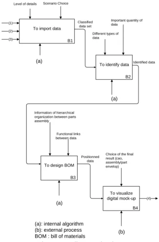
A second SADT diagram (level B0) is presented below and it goes back over the different steps decomposition:
B2 To identify data B3 To design BOM B4 To visualize digital mock-up B1 To import data (1) (4) Identified data Positionned data Classified data set Different types of data Important quantity of data
Choice of the final result (cao, assembly/part envelop) Information of hierarchical
organization between parts assembly
(3) (2)
(a)
Level of details Scenario Choice
(a)
(a)
(b) (a): internal algorithm
(b): external process BOM : bill of materials
Functional links between data
Fig. 2 SADT diagram - level B0
- B1 consists in retrieving all the heterogeneous data and instantiate them the same in DBMS1
solutions. - B2 relies on first analysing each heterogeneous data
and, thanks to techniques of segmentation, identifying one or many parts inside each file and get component intrinsic data (set of pixel, edge parts, etc.). Then, it enables to match the different representations of a same component (picture, 3D CAD model, etc.). The output data of this step is encapsulated in a knowledge data base.
- B3 is similar to B2 but it deals with extrinsic data such as functional surfaces between several components. The output data corresponds to the functional (assembly) signature.
- B4 is the last step of the process which is to visualize the mechanical assembly (BOM2
) according to the control parameters, in the wished context.
A knowledge data base using ontology concepts enables to identify a type of components (crankshaft, piston rod, etc.). To start, several ontologies of mechanical component will be developed. The ontology concept is not presented in this paper and concerns the first research work presented in the beginning of section 3.
Once all components are identified in the heterogeneous dataset, it is necessary to extract information in order to design the engineering BOM which enables then to give a digital mock-up. Now let’s decompose the signature mechanism (B2) as presented below.
The decomposition is described as following:
- B21 is relying on solution existing on the market in terms of data segmentation whatever the type - B22 consists in a first “scanning” of the data. If the
segment is recognized, the next step is automatic. In the contrary, the user has to helps the software either to find the component corresponding in the database either to add it to the knowledge database.
- B23 enables to give a geometrical mark (Cartesian coordinate system) to the segment and give also dimension so as to calibrate it.
- B24 is the second signature which permits to recognize topologic elements such as vertex, edges, planes, mesh, etc. and features.
- B25 consists in comparing if the segment identified previously has similarities with another segment issued of the current integration of heterogeneous data (B1 - Fig. 1 SADT Diagram of METIS' process) - B26 is the last step of B2, it consists in gathering all
the signatures corresponding to a same component and in enhancing the signature database. The data retrieved enable to give a set of specific signatures (geometrical information extracted) of the considered part.
In the next subsection, we suggest to illustrate the main concept of the process through a case of study. We focus on the level B2 which is the innovative point of our contribution.
1
DBMS : Data Base Management System
M.Bruneau et al. Towards new processes to reverse engineering digital mock-ups from a set of heterogeneous data.
June 19th – 21st, 2013, Madrid, Spain Congress INGEGRAF-ADM-AIP PRIMECA B21
To segment data
(5)
(5) Classified data set
(*) if segment data is not recognized > the user has to add the reference manually
(6) Signatures associated to a component
Types of data B22 To sign data Recognized shapes Proper algorithm to a type of data METIS algorithm B23 To add geometrical mark
Segment shape recognized Types of data Types of data METIS algorithm (*) B24 To sign topologically Segment oriented and calibrated Types of segment Knowledge data base
Knowledge data base
METIS algorithm B25 To match identical segments Segment identified METIS algorithm Knowledge data base
(6) B26 To capitalize signature Segment equivalence
Knowledge data base
METIS algorithm
Fig. 3 SADT - level B2
3.2 Illustration
A real case study has been chosen. The choice has been oriented to a car engine available in order to take picture, scan different parts or retrieve some information from the maintenance’s guide. The case study considered is the engine of an old French car (Citroen 2CV). The heterogeneous data available are: (1) pictures of the piston with several points of view; (2) drawings from technical documents; (3) scan data of the external surfaces.
The use-case “from scratch” is considered because we assume that it is the most restrictive (it means that this use-case starts without initial digital mock-up).
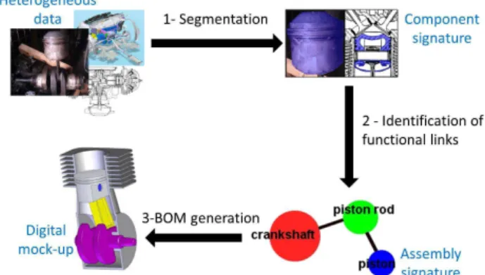
An illustration is given on a figure 5. There are different states for the data and operations (1-2-3) applied to go from one to the other step. The two main steps can be defined by signature whose two types can be: geometric and shape one and functional one corresponding respectively to component and assembly characterizations.
Fig. 5 Illustration of the case study in the whole process
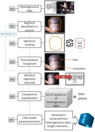
We propose to decompose the level B2 as following. Each step is in link with the pictures of the figure 6. The decomposition is:
- B21: the chosen data are in one hand, a picture showing the piston with the piston rod and the crankshaft and on the other hand, a 2D drawing representing a cross-section view of the full car engine
-
B22: one of the data is selected and analysed until locating a shape corresponding to a component. Then its edges can be identified.- B23: this step consists in searching in the ontological data base if the segment obtained in B22 has similarities with another known part (same signature). - B24: then the piston features are recognized.
- B25: once all the geometry is retrieved, the software compares this geometric signature to the other data issued of the integration (2D drawing here).
- B26: to finish, signatures corresponding to the same component are combined to be defined as a characterization of the piston, enhancing the data base.
- B27: the information retrieved (length, diameter...) enable to redesign the parameterized CAD model. NB: if there is any correspondence in B23 with the signature database, the user will realize the next steps manually.
M.Bruneau et al. Towards new processes to reverse engineering digital mock-ups from a set of heterogeneous data.
June 19th – 21st, 2013, Madrid, Spain Congress INGEGRAF-ADM-AIP PRIMECA Fig. 6 Illustration on a piston
4
Discussion
In one hand, this approach enabled to validate the scientific bolts identified in the national French project. Indeed, the state of the art and the decomposition showed the different shortage whether it is in software solutions or in literature. Moreover, the detailed approach gave all the technical functions that will have to be performed.
In the other hand, this study is simplified and the assumptions are numerous so the planned results are quite subjective. A more accurate state of the art needs to be done in order to increase the chance to get the best result, adaptable to a large range of heterogeneous data.
5
Conclusion
This paper proposes an approach for a specific need in Reverse Engineering which is generally used to get back the 3D geometrical model of a unique physical data. This problematic follows from an industrial need in the automotive field whose aim is to deal with digital mock-ups of more than a hundred of components. The national French Project has been launched to reply to the problematic.
A scenario in four steps enables to make a decomposition of the different scientific bolts which have been raised and has been illustrated with SADT diagrams. Then the automation of the process to link the integration of heterogeneous data to a digital mock-up, is another difficulty highlighted in this paper. An example of a piston from an engine car permitted to validate this approach.
The continuation of this study will articulate around the proposal of a model of data relying on the process
proposed in this paper. A software demonstrator would be developed in the next 24 months.
Acknowledgement
These works have been supported by the ANR (National Agency of Research) through the Numerical Model program (Project METIS – 12-MONU-004)
References
[1] T. Varady, R. R. Martin, Jordan Coxt. Reverse Engineering of geometric models-an introduction. In Computer-Aided Design 1997. Vol. 29, No 4, pp. 255-268
[2] ANR-07-MDCO-015 MADRAS. French project. Technical report. 2011
[3] ANR BLANC SATTIC. French project. Technicla report. 2007
[4] IMAGEG3D – Project finished in 2012. Technical report.
[5] ANR ARA MMSA 0001 – EROS 3D – French project – Technical report. 2005 [6] PHENIX COSINUS N°08-COSI-011 –
French project. Technical report pp.1-28. [7] Dengsheng Zhang, Guojun Lu, Review of
shape representation and description techniques, Pattern Recognition, Vol. 37, No. 1. (January 2004), pp. 1-19.
[8] A. Amanatiadis, V.G. Kaburlasos, A. Gasteratos, S.E. Papadakis, Evaluation of shape descriptors for shape-based image retrieval, IET Image Processing, 2011, Vol. 5, Iss. 5, pp. 493–499.
[9] L. De Luca, P. Véron, M. Florenzo. Reverse engineering of architectural buildings based on a hydrid modeling approach, Computer & Graphics 30, 2006, pp 160-176
[10] W.B. Thompson, J.C. Owen, J. De St Germain, S.R. Stark, T.C. Henderson. Feature based reverse engineering of mechanical parts, IEEE Transactions on Robotics and Automotion, 1999, 15(1),pp. 557-66
[11] T. Chaperon, F. Goulette. Extracting cylinders in full 3D data using a random sampling method ans the Gausian image. Proceedings of Stuggart 2001, pp. 35-42 [12] B. Bernard, F. Laroche, S.
Ammar-Khodja, N. Perry. Impact of new 3D numerical devices environments on redesign valorization of mechanical systems. CIRPS Annals Manufacturing Technology, Elsevier, v56, pp 143-148 [13] Panchetti, J-P. Pernot, P. Véron, Towards
recovery of complex shapes in meshes using digital images for reverse engineering applications, 2010, Computer-Aided Design, vol. 42(8), pp. 693-707