HAL Id: tel-01153225
https://tel.archives-ouvertes.fr/tel-01153225
Submitted on 19 May 2015
HAL is a multi-disciplinary open access archive for the deposit and dissemination of sci-entific research documents, whether they are pub-lished or not. The documents may come from teaching and research institutions in France or
L’archive ouverte pluridisciplinaire HAL, est destinée au dépôt et à la diffusion de documents scientifiques de niveau recherche, publiés ou non, émanant des établissements d’enseignement et de recherche français ou étrangers, des laboratoires
N˚d’ordre 2014-ISAL–XXXX Année 2014
THÈSE
SIMULATION OF COLD SPRAY PARTICLE DEPOSITION
PROCESS
Présentée devant
l’Institut National des Sciences Appliquées de Lyon
pour obtenir
le GRADE DE DOCTEUR
École doctorale :
Mécanique, Énergétique, Génie Civil, Acoustique
Spécialité :
MÉCANIQUE - GÉNIE MÉCANIQUE - GÉNIE CIVIL
par
Jing XIE
thèse soutenue le 27 Mai 2014 devant la Commission d’examen
Jury
VINCENTGUIPONT ENSMP, Paris Chercheur (HDR) Rapporteur
GHISLAINMONTAVON UTBM, Belfort Professeur Rapporteur
PHILIPPEBERTRAND ENISE, Saint-Etienne Maître de Conférences (HDR) Examinateur
ALAINCOMBESCURE INSA, Lyon Professeur Examinateur
BERNARDNORMAND INSA, Lyon Professeur Examinateur
KAZUHIRO OGAWA Tohoku Univ., Sendai Professeur Examinateur
DANIELNÉLIAS INSA, Lyon Professeur Directeur de thèse
HÉLÈNEWALTER-LE BERRE INSA, Lyon Maître de Conférences Co-encadrant
YUJI ICHIKAWA Tohoku Univ., Sendai Professeur Adjoint Invité
STÉPHANEKNITTEL SNECMA, Corbeil Ingénieur de Recherche Invité
VINCENTROBIN AREVA NP, Lyon Expert Invité
INSA Direction de la Recherche INSA Direction de la Recherche INSA Direction de la Recherche
INSA Direction de la Recherche ---- Ecoles Doctorales Ecoles Doctorales Ecoles Doctorales –––– Quinquennal 2011Ecoles Doctorales Quinquennal 2011Quinquennal 2011----2015Quinquennal 201120152015 2015
SIGLE ECOLE DOCTORALE NOM ET COORDONNEES DU RESPONSABLE
CHIMIE
CHIMIE DE LYON
http://www.edchimie-lyon.fr Sec : Renée EL MELHEM Bat Blaise Pascal 3e etage
04 72 43 80 46 Insa : R. GOURDON
M. Jean Marc LANCELIN
Université de Lyon – Collège Doctoral Bât ESCPE 43 bd du 11 novembre 1918 69622 VILLEURBANNE Cedex Tél : 04.72.43 13 95 [email protected] E.E.A. ELECTRONIQUE, ELECTROTECHNIQUE, AUTOMATIQUE http://edeea.ec-lyon.fr Sec : M.C. HAVGOUDOUKIAN [email protected] M. Gérard SCORLETTI
Ecole Centrale de Lyon 36 avenue Guy de Collongue 69134 ECULLY Tél : 04.72.18 60.97 Fax : 04 78 43 37 17 [email protected] E2M2 EVOLUTION, ECOSYSTEME, MICROBIOLOGIE, MODELISATION http://e2m2.universite-lyon.fr Sec : Safia AIT CHALAL Bat Darwin - UCB Lyon 1 04.72.43.28.91
Insa : H. CHARLES
Mme Gudrun BORNETTE
CNRS UMR 5023 LEHNA Université Claude Bernard Lyon 1 Bât Forel 43 bd du 11 novembre 1918 69622 VILLEURBANNE Cédex Tél : 06.07.53.89.13 e2m2@ univ-lyon1.fr EDISS INTERDISCIPLINAIRE SCIENCES-SANTE http://www.ediss-lyon.fr Sec : Safia AIT CHALAL Hôpital Louis Pradel - Bron 04 72 68 49 09
Insa : M. LAGARDE
Mme Emmanuelle CANET-SOULAS
INSERM U1060, CarMeN lab, Univ. Lyon 1 Bâtiment IMBL
11 avenue Jean Capelle INSA de Lyon 696621 Villeurbanne Tél : 04.72.68.49.09 Fax :04 72 68 49 16 [email protected] INFOMATHS INFORMATIQUE ET MATHEMATIQUES http://infomaths.univ-lyon1.fr Sec :Renée EL MELHEM Bat Blaise Pascal 3e etage
Mme Sylvie CALABRETTO
LIRIS – INSA de Lyon Bat Blaise Pascal 7 avenue Jean Capelle 69622 VILLEURBANNE Cedex Tél : 04.72. 43. 80. 46 Fax 04 72 43 16 87 [email protected] Matériaux MATERIAUX DE LYON http://ed34.universite-lyon.fr Sec : M. LABOUNE PM : 71.70 –Fax : 87.12 Bat. Saint Exupéry
M. Jean-Yves BUFFIERE
INSA de Lyon MATEIS
Bâtiment Saint Exupéry 7 avenue Jean Capelle 69621 VILLEURBANNE Cedex
Tél : 04.72.43 83 18 Fax 04 72 43 85 28
MEGA
MECANIQUE, ENERGETIQUE, GENIE CIVIL, ACOUSTIQUE
http://mega.universite-lyon.fr Sec : M. LABOUNE
PM : 71.70 –Fax : 87.12 Bat. Saint Exupéry
M. Philippe BOISSE
INSA de Lyon Laboratoire LAMCOS Bâtiment Jacquard 25 bis avenue Jean Capelle 69621 VILLEURBANNE Cedex Tél :04.72 .43.71.70 Fax : 04 72 43 72 37 [email protected] ScSo ScSo* http://recherche.univ-lyon2.fr/scso/ Sec : Viviane POLSINELLI
Brigitte DUBOIS Insa : J.Y. TOUSSAINT
Mme Isabelle VON BUELTZINGLOEWEN
Université Lyon 2 86 rue Pasteur 69365 LYON Cedex 07
Tél : 04.78.77.23.86 Fax : 04.37.28.04.48
All the art of living lies in a fine
mingling of letting go and holding on.
- Henry Ellis
Abstract
Cold spray is a rapidly developing coating technology for depositing materials in the solid state. The cold spray particle deposition process was simulated by modeling the high velocity impacts of spherical particles onto a flat substrate under various conditions. We, for the first time, proposed the Couple Eulerian Lagrangian (CEL) numerical approach to solve the high strain rate deformation problem. The capability of the CEL numerical ap-proach in modeling the Cold Spray deposition process was verified through a systematic parameter study, including impact velocity, initial particle temperature, friction coefficient and materials combination. The simulation results by using the CEL numerical approach agree with the experimental results published in the literature. Comparing with other nu-merical approaches, which are Lagrangian, ALE and SPH, the CEL analyses are generally more accurate and more robust in higher deformation regimes.
Besides simulating the single particle impact problem, we also extended our study into the simulation of multiple impacts. A FCC-like particles arrangement model that inspired by the crystal structure was built to investigate the porosity rate and residual stress of de-posited particles under various conditions. We observed not only the 3D profiles of voids, but also their distributions and developments during different procedures. Higher impact velocity and higher initial temperature of particles are both of benefit to produce a denser cold spray coating. The compressive residual stresses existed in the interface between the particle and substrate is mainly caused by the large and fast plastic deformation. Another simplified model for multiple impacts was created for the simulation of surface erosion. A severe surface erosion is the result of a high impact velocity, a high friction coefficient and a low contact angle.
Two element failure models suitable for high-strain-rate dynamic problems were intro-duced in this study. One is shear failure model driven by Johnson-Cook plastic yielding ; another one is called tensile failure model, which the material fails when the mean stress reaches the ultimate tensile strength. For a ductile material as Copper, it followed two fracture modes in our study, which are tensile failure mode and shear failure mode. The former one mainly occurred beneath the substrate surface and the periphery of substrate craters, nevertheless the latter one was found predominately at the surface of craters. Four steps were found during the propagation of crack : void formation ; crack formation ; crack growth ; coalescence and failure. A simple criterion equation was derived based on the si-mulation results for predicting the initiation of damage, which the erosion velocity verois
a function of contact angle θ and erosion velocity for normal impact vπ/2. The equivalent
plastic strain could also be a parameter for identifying the onset of damage, identified as being 1.042 for Copper in our study.
K
EY WORDS:
Cold Spray, CEL, multiple impacts, Porosity rate, Residual stress, Erosion rate, FractureRésumé
La projection à froid est une technologie en plein essor pour le dépôt de matériaux à l’état solide. Le procédé de dépôt des particules par pulvérisation à froid est simulé par la modélisation de l’impact à haute vitesse de particules sphériques sur un substrat plat dans diverses conditions. Pour la première fois, nous proposons une approche numérique par couplage Euler-Lagrange (CEL) afin de résoudre ce problème à haute vitesse de défor-mation. Les capacités de l’approache numérique CEL pour la modélisation du processus de dépôt de projection à froid sont évaluées par une étude paramétrique de : la vitesse d’impact, la température initiale des particules, le coefficient de frottement et le choix des matériaux. Les résultats de la simulation à l’aide de l’approche numérique CEL sont en accord avec les résultats expérimentaux publiés dans la littérature. La méthode CEL est généralement plus précise et plus robuste dans des régimes de déformations élevées que d’autres méthodes numériques de type Lagrangienne, ALE ou SPH.
Outre la simulation du problème de l’impact unique, nous étendrons également notre étude à la simulation des impacts multiples. Un nouveau modèle d’empilement de type CFC, inspiré de la structure cristalline, est construit afin d’étudier le taux de porosité des particules déposées et les contraintes résiduelles dans le matériau de substrat pour diverses conditions. Nous pouvons observer non seulement la goémétrie 3D de porosités, mais aussi leur répartition et leur évolution pendant les impacts successifs. Pour les particules, une vitesse d’impact et une température initiale élevées, sont des avantages pour produire des revêtements denses par projection à froid. Des contraintes résiduelles de compression existent à l’interface entre les particules et le substrat. Ces dernières sont causées par les grandes amplitudes et vitesses de déformation plastique induites par le procédé. Un second modèle moins complexe pour la modélisation de l’impact multiple oblique a été créé afin de simuler l’érosion de surface. Une forte érosion de surface est le résultat : d’une plus grande vitesse d’impact, d’un coefficient de frottement élevé et d’un angle de contact réduit.
Deux modèles d’endommagement particulièrement adaptés pour les problèmes à forte vitesse de déformation sont introduits dans cette étude. L’un est le modèle de rupture par cisaillement plastique de Johnson-Cook (mode 2) ; l’autre est un modèle d’endom-magement en traction (mode 1), où le matériau disparaît lorsque la contrainte moyenne atteint la striction. Pour un matériau ductile comme le cuivre, il y a deux modes de rup-ture : le mode 1 de traction et le mode 2 de ruprup-ture par cisaillement. Le premier survient principalement en dessous de la surface du substrat et à la périphérie de impacts, tandis que le second intervient de manière prédominante à la surface des impacts. On observe quatre étapes lors de la propagation des fissures : la formation de porosités, de fissures, la croissance de ces dernières, puis une dernière étape de coalescence et rupture. Un critère simple, où la vitesse d’érosion vero est fonction de l’angle de contact θ et de la vitesse
critique d’érosion lors d’un impact de vitesse normale vπ/2, est proposé sur la base des résultats des simulations afin de prédire l’initiation de l’endommagement. La déforma-tion plastique équivalente est également un paramètre clef pour identifier l’initiadéforma-tion de
Contents
Contents i
List of Figures v
List of Tables ix
Introduction 1
1 Previous researches on the cold spray deposition process 3
1.1 Cold spray coating technology . . . 5
1.1.1 Coating formation process . . . 5
1.1.2 Advantages and disadvantages . . . 5
1.1.3 Bonding mechanism . . . 6
1.1.4 Application . . . 8
1.2 Numerical approach . . . 9
1.2.1 Lagrangian . . . 9
1.2.2 Arbitrary Lagrangian Eulerian . . . 9
1.2.3 Smoothed Particle Hydrodynamics . . . 10
1.2.4 Coupled Eulerian Lagrangian . . . 10
1.3 Previous studies . . . 11
1.3.1 Simulation of cold spray . . . 11
1.3.2 Effect of parameters . . . 14
1.3.3 Experimental results . . . 17
1.4 Objectives . . . 22
2 Feasibility of numerical approach 25 2.1 Problem description . . . 27
2.2 Basic assumptions . . . 27
2.3 Lagrangian . . . 28
2.3.1 Model description . . . 28
2.3.2 Results and discussion . . . 34
2.4 Arbitrary Lagrangian Eulerian . . . 36
2.4.1 Model description . . . 36
2.7.1 Comparison of four numerical approaches . . . 48
2.7.2 Typical impact behaviors of cold sprayed particle and substrate . . 50
2.8 Summary . . . 54
3 Simulation of single impact 55 3.1 Simulation outline . . . 57
3.2 Velocity . . . 57
3.2.1 Deformation shape . . . 57
3.2.2 Evolution of the strain and temperature . . . 59
3.3 Temperature . . . 60
3.3.1 Deformation shape . . . 60
3.3.2 Evolution of the strain and temperature . . . 61
3.4 Friction coefficient . . . 63
3.4.1 Deformation shape . . . 63
3.4.2 Evolution of the strain and temperature . . . 63
3.5 Material . . . 64
3.5.1 Deformation shape . . . 64
3.5.2 Evolution of the strain and temperature . . . 65
3.6 Discussion . . . 66
3.6.1 Energy dissipation and restitution coefficient . . . 66
3.7 Summary . . . 69
4 Simulation of multiple impacts 71 4.1 Simulation outline . . . 72 4.2 Deformation shape . . . 73 4.3 Porosity rate . . . 74 4.4 Residual stress . . . 77 4.5 Summary . . . 79 5 Simulation of erosion 81 5.1 Simulation outline . . . 83
5.1.1 Dynamic failure model . . . 83
5.2 Oblique impact . . . 85
5.2.1 Deformation shape . . . 85
5.2.2 Evolution of the strain and temperature . . . 86
Contents 5.3.1 Contact angle . . . 88 5.3.2 Velocity . . . 89 5.3.3 Friction coefficient . . . 90 5.3.4 Multiple impacts . . . 91 5.4 Discussion . . . 91 5.4.1 Fracture . . . 91 5.5 Summary . . . 93 Conclusions 95
Appendix A: Significance of the substrate size in simulations of the normal im-pact of a sphere with a half-space. 99 Appendix B: The temperature-dependent material property for Aluminum and
Copper 101
Appendix C: Comparison of Analysis Procedures 105 Appendix D: Contact pair algorithm in ABAQUS/Explicit 107 Appendix E: ALE adaptive mesh controls 111 Appendix F: Finite element conversion to SPH particles 113 Appendix G: Assigning materials to Eulerian part 121 Appendix H: Modeling surface erosion 123 Appendix I: Progressive damage and failure 125 Appendix J: Damage initiation criterion 131
List of Figures
1.1 The schematic diagram of cold spray apparatus. . . 5 1.2 The stages of coating formation in the cold spray deposition process [STE 02]. 5 1.3 Microstructural changes across the interfacial zone. (a) Dendrites inside
the intermetallic inclusion. Microstructures of the base plates in areas directly adhering to the intermetallic inclusion: (b) elongated subgrains inside the aluminum sheet and (c) ?ne grains inside copper sheet. TEM bright ?eld images in the ND-TD section [HEN 13]. . . 6 1.4 The structures of the cross sections of the samples for three different
val-ues of Detonation velocity (D) and at the same thickness of explosive charge ? 5 mm: (a) D=3.19 km/s; (b) D=3.95 km/s; (c) D=5.26 km/s [BUZ 13]. . . 6 1.5 (a) Typical stress-strain curves in a normal strainhardening material
(‘Isother-mal’), an adiabatically softened material (‘Adiabatic’) and in a material undergoing an adiabatic shear localization (‘Localization’); (b) schemat-ics of the uniform and the localized simple shears [CHA 05]. . . 8 1.6 (a) Low-magnification TEM image of interfacial microstructures between
as-sprayed Ni coatings and Al-6061-T6 alloy substrate in a kinetic spray process. HREM images of boxed region-1 (b) and region-2 (c) in (a) [XIO 08]. . . 8 1.7 The schematic diagram (a) of mechanical interlocking [GRU 03] and EDS
image (b) of Cu(particle)/Al(substrate) [CHA 05]. . . 8 1.8 Computed air and particle velocities as function of distance along the
noz-zle [STE 99]. . . 15 1.9 Computed air and particle temperatures as function of distance along the
nozzle [STE 99]. . . 15 1.10 Different splat morphologies observed by SEM as a function of positions
from the center of the particle jet: (a) near the center, (b) intermediate position and (c) near the rim. . . 17 1.11 Schematic diagram of the dependence of relative deposition efficiency on
spray angle [LI 05]. . . 17 1.12 Etched Cross section micrographs of coatings obtained at a particle
1.16 Measurement (symbols) and model fit (solid lines) of the through thick-ness in-plane stress distributions for (a) Cu/Cu sample, (b) Cu/Al sample,
(c) Al/Cu sample and (d) Al/Al sample [LUZ 11]. . . 20
1.17 Residual stress in as-received specimens coated with Al7075 and pure Al [GHE 12]. . . 20
1.18 Temperature and curvature graphs of Ti/Carbon steel coating, illustrating the concepts of evolving, deposition, thermal and final residual stresses [SUH 13]. . . 21
1.19 The erosive failure behavior of brittle and ductile materials: (a) erosion on brittle materials; (b) erosion on ductile materials [WAN 08]. . . 21
1.20 Crater shape in (a) ductile and (b) brittle materials [RUF 79, AQU 01]. . . 21
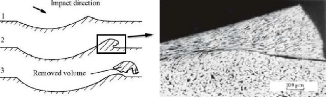
1.21 Longitudinal section of the impact crater left in mild steel when hit by hardened steel ball R = 4.75 mm, α = 30˚, v0 = 141 m/s : (a) material removal, (b) microphoto of special zone in the black rectangle indicated at (a) [HUT 76]. . . 22
1.22 SEM observations for craters of Aluminum obtained by the impact tests of WC balls at impact angles of (a) 20˚, (b) 30˚, (c) 40˚, (d) 60˚ and (e) 90˚ at an impact velocity of 100 m/s [OKA 03]. . . 22
1.23 A photograph of a crater caused by WC ball impact at an impact velocity of 2500 m/s at 30˚ for Aluminium [OKA 05c]. . . 22
1.24 Cross-sectional surface of Aluminium at impact velocities of (a) 100 m/s, (b) 1320 m/s and (c) 2270 m/s [OKA 05c]. . . 23
1.25 Scanning electron micrograph taken from periphery of erosion scar show-ing ductile erosion mechanisms for (a) 316 stainless steel eroded at 90 m/s for a dwell time of 180 s, 30.4 µm powder at 15˚; (b) Stellite 12 eroded at 130 m/s for a dwell time of 120 s, 30.4 µm powder at 15˚; (c) 316 stainless steel eroded at 130 m/s for a dwell time of 180 s, 6.9 µm powder at 15˚ [AKB 12]. . . 23
2.1 SEM image of Al feedstock powder . . . 27
2.2 Schematic diagram of 2D axisymmetric model. . . 28
2.3 Schematic diagram of surface-to-surface contact. . . 33
2.4 Schematic diagram of boundary condition of 2D axisymmetry model. . . 33
2.5 Schematic diagram of initial conditions of velocity and temperature. . . . 34
List of Figures
2.7 Contours of (a) equivalent plastic strain and (b) temperature of Al/Al by using the Lagrangian numerical approach at 700 m/s - aborted at 19 ns. . 35 2.8 Element distortion of (a) Al particle and (b) Al substrate by using the
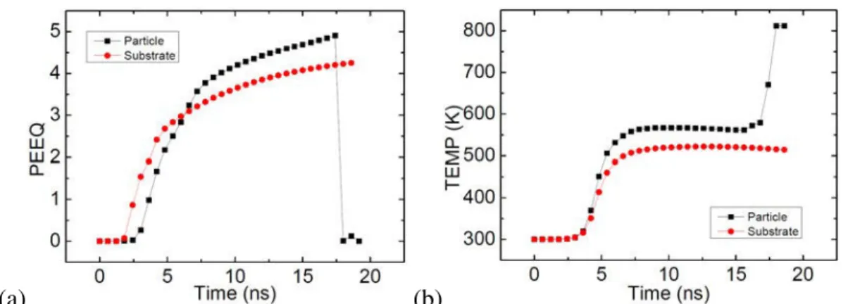
Lagrangian numerical approach at 700 m/s. . . 35 2.9 Time histories of (a) equivalent plastic strain (PEEQ) and (b) temperature
of Al/Al by using the Lagrangian numerical approach at 700 m/s. . . 36 2.10 Schematic diagram of the ALE adaptive mesh domain. . . 36 2.11 Schematic diagrams of detection and deactivation of geometric features. . 37 2.12 Contours of (a) equivalent plastic strain and (b) temperature of Al/Al by
using the ALE numerical approach at 700 m/s. . . 38 2.13 Time histories of (a) equivalent plastic strain (PEEQ) and (b) temperature
of Al/Al by using the ALE numerical approach at 700 m/s. . . 39 2.14 Schematic diagram of 3D SPH model. . . 40 2.15 Schematic diagram of transformation of C3D8R element to PC3D elements. 42 2.16 Schematic diagram of kernel interpolate function. . . 42 2.17 Schematic diagram of cube centred at the PC3D element. . . 42 2.18 Contour of equivalent plastic strain of Al/Al by using the SPH numerical
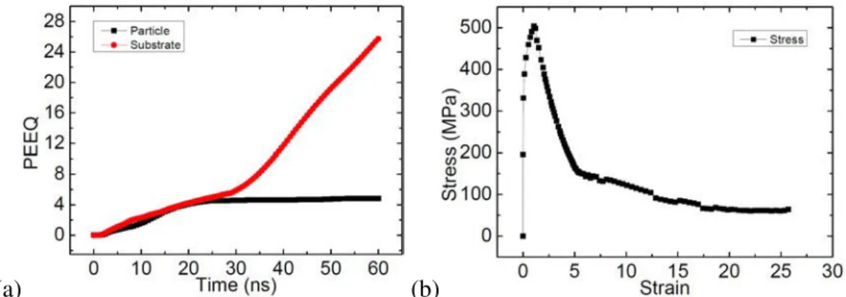
approach at 700 m/s. . . 44 2.19 Time histories of (a) equivalent plastic strain (PEEQ) of Al/Al and (b)
stress of substrate by using the SPH approach at 700 m/s. . . 44 2.20 Schematic diagram of 3D CEL model. . . 45 2.21 Boundary conditions for the 3D CEL model. . . 46 2.22 Contours of (a) volume average equivalent plastic strain of Al particle and
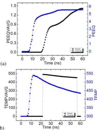
(b) equivalent plastic strain of Al substrate by using the CEL numerical approach at 700 m/s. . . 48 2.23 Contours of (a) volume average temperature of Al particle and (b)
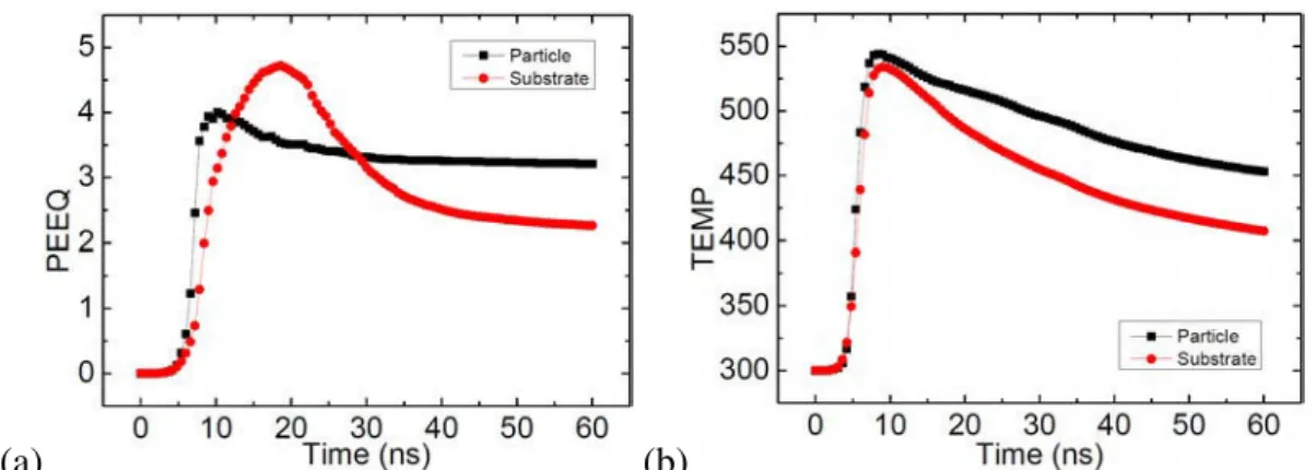
tem-perature of Al substrate by using the CEL numerical approach at 700 m/s. 48 2.24 Time histories of (a) equivalent plastic strain (PEEQ) and (b) temperature
of Al/Al by using the CEL approach at 700 m/s. . . 48 2.25 Time histories of normalized displacement of specific nodes by using the
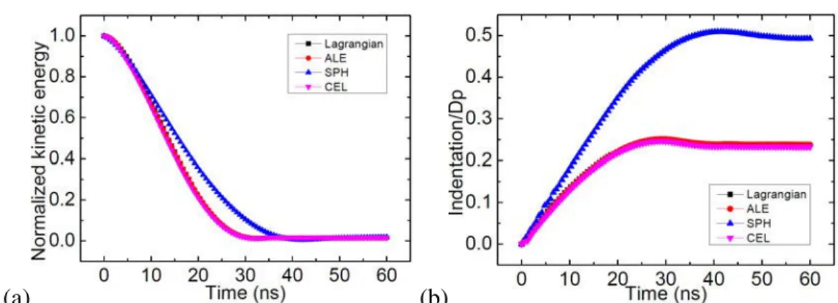
ALE approach. . . 49 2.26 Time histories of (a) normalized kinetic energy and (b) normalized
dis-placement of substrate center by using the four approaches at 700 m/s. . . 49 2.27 Time histories of (a) stable time increment and (b) artificial strain energy
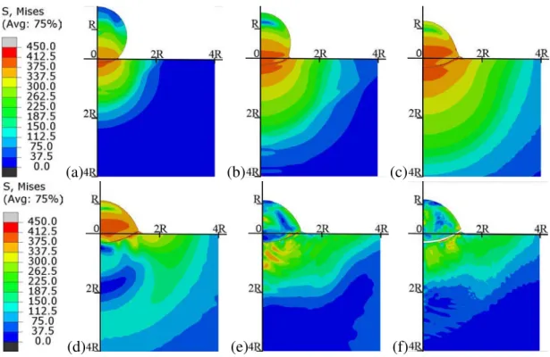
by using the four approaches at 700 m/s. . . 50 2.28 Evolution of Von Mises stress of Al/Al at 500 m/s. (a) 5 ns; (b) 10 ns; (c)
20 ns; (d) 30 ns; (e) 40 ns; (f) 60 ns. . . 51 2.29 Evolution of mean stress of Al/Al at 500 m/s. (a) 5 ns; (b) 10 ns; (c) 20
ns; (d) 30 ns; (e) 40 ns; (f) 60 ns. . . 51 2.30 Evolution of equivalent plastic strain (PEEQ) of Al/Al at 500 m/s. (a) 5
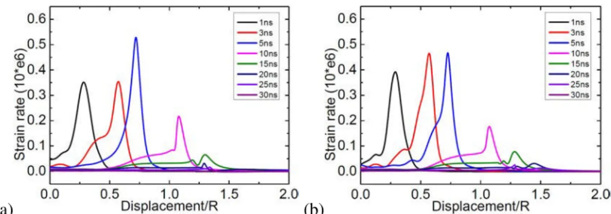
ns; (b) 10 ns; (c) 20 ns; (d) 30 ns; (e) 40 ns; (f) 60 ns. . . 52 2.31 Evolution of strain rate along the horizontal direction of contact surface
of Al substrate impacted by an Al particle at 500 m/s. . . 54 3.1 Schematic diagrams of path 1 and path 2. . . 57 3.2 SEM images of Al/Al at impact velocity of (a) 700 m/s, (b) 780 m/s and
(c) 840 m/s. . . 58 3.3 Simulation profiles of Al/Al at impact velocity of (a) 700 m/s, (b) 780
m/s and (c) 840 m/s. . . 59 3.4 Time histories of (a) equivalent plastic strain (PEEQ) and (b) temperature
(TEMP) of Al/Al by using the CEL numerical approach at 700 m/s, 780 m/s and 840 m/s. . . 59 3.5 Developments of equivalent plastic strain (PEEQ) along the path 1 of
Al/Al by using the CEL numerical approach at (a) 700 m/s and (b) 840 m/s. . . 60 3.6 Developments of temperature (TEMP) along the path 1 of Al/Al by using
the CEL numerical approach at (a) 700 m/s and (b) 840 m/s. . . 60 3.7 Equivalent plastic strain (PEEQ) along the (a) path 1 and (b) path 2 of
Al/Al by using the CEL numerical approach at 700 m/s, 780 m/s and 840 m/s. . . 60 3.8 Temperature (TEMP) along the (a) path 1 and (b) path 2 of Al/Al by using
the CEL numerical approach at 700 m/s, 780 m/s and 840 m/s. . . 61 3.9 (a) SEM image and (b) simulation profile of Cu/Al with an initial particle
temperature of 873 K . . . 61 3.10 Time histories of (a) equivalent plastic strain (PEEQ) and (b) temperature
(TEMP) of Cu/Al by using the CEL numerical approach at the initial particle temperatures of 473 K, 673 K and 873 K. . . 61 3.11 Developments of equivalent plastic strain (PEEQ) along the path 1 of
Cu/Al by using the CEL numerocal approach at the initial particle tem-peratures of (a) 473 K and (b) 873 K. . . 62 3.12 Developments of temperature (TEMP) along the path 1 of Cu/Al by using
the CEL numerical approach at the initial particle temperatures of (a) 473 Kand (b) 873 K. . . 62 3.13 Equivalent plastic strain (PEEQ) along the (a) path 1 and (b) path 2 of
Cu/Al by using the CEL numerical approach at the initial particle temper-atures of 473 K, 673 K and 873 K. . . 63
List of Figures
3.14 Temperature (TEMP) along the (a) path 1 and (b) path 2 of Cu/Al by using the CEL numerical approach at the initial particle temperatures of 473 K, 673 K and 873 K. . . 63 3.15 Simulation profiles of Cu/Cu with friction coefficient of (a) 0.2 and (b)
0.5 by Li. et al [LI 09a] using the Lagrangian numerical approach. . . 63 3.16 Simulation profiles of Cu/Cu with friction coefficients of (a) 0.2 and (b)
0.5 by using the CEL numerical approach. . . 64 3.17 Time histories of (a) equivalent plastic strain (PEEQ) and (b) temperature
(TEMP) of Cu/Cu by using the CEL numerical approach with friction coefficients of 0.2, 0.3 and 0.5. . . 64 3.18 Time histories of friction energy (ALLFD) divided by internal energy
(ALLIE) of Cu/Cu by using the CEL numerical approach with friction coefficients of 0.2, 0.3 and 0.5. . . 64 3.19 Developments of equivalent plastic strain (PEEQ) along the path 1 of
Cu/Cu by using the CEL numerical approach with friction coefficients of (a) 0.2 and (b) 0.5. . . 65 3.20 Developments of temperature (TEMP) along the path 1 of Cu/Cu by using
the CEL numerical approach with friction coefficients of (a) 0.2 and (b) 0.5. 65 3.21 Equivalent plastic strain (PEEQ) along the (a) path 1 and (b) path 2 of
Cu/Cu by using the CEL numerical approach with friction coefficients of 0.2, 0.3 and 0.5. . . 65 3.22 Temperature (TEMP) along the (a) path 1 and (b) path 2 of Cu/Cu by
using the CEL numerical approach with friction coefficients of 0.2, 0.3 and 0.5. . . 66 3.23 (a) SEM image and (b) simulation profile of Al/Cu at impact velocity of
500 m/s . . . 66 3.24 Time histories of (a) equivalent plastic strain (PEEQ) and (b) temperature
(TEMP) of Al/Al, Cu/Cu, Al/Cu and Cu/Al by using the CEL numerical approach at 500 m/s. . . 66 3.25 Developments of (a) equivalent plastic strain (PEEQ) and (b) temperature
(TEMP) along the path 1 of Al/Cu by using the CEL numerical approach at 500 m/s. . . 67 3.26 Time histories of normalized kinetic energy by using the CEL numerical
approach at 500 m/s. (a) 0 - 60 ns; (b) 40 - 60 ns. . . 67 3.27 Equivalent plastic strain (PEEQ) along the (a) path 1 and (b) path 2 of
Al/Al, Cu/Cu, Al/Cu and Cu/Al by using the CEL numerical approach at 500 m/s. . . 67 3.28 Temperature (TEMP) along the (a) path 1 and (b) path 2 of Al/Al, Cu/Cu,
Al/Cu and Cu/Al by using the CEL numerical approach at 500 m/s. . . . 68 3.29 Rebound velocities of (a) Al particle and (b) Al substrate at 500 m/s. . . . 68
4.1 Schematic diagrams of three kinds of cubic unit cell, which are (a) simple cubic, (b) body center cubic and (c) face center cubic. . . 73 4.2 Schematic diagram of the combination of two FCC particles arrangement
models. . . 73 4.3 Schematic diagram of the 3D CEL model with quarter symmetry. . . 73 4.4 Landing location for a particle range between 5 and 60 µm for a flat
sub-strate, placed at a standoff distance of 10 mm [SAM 07]. . . 74 4.5 Secondary electron micrographs of the cross-section of (a) Al/Al and (b)
Cu/Cu. . . 74 4.6 Simulation profiles of (a) Al/Al and (b) Cu/Cu by using the FCC particles
arrangement model. . . 74 4.7 Simulation contours of pores for (a) Al/Al and (b) Cu/Cu by using the
FCC particles arrangement model. . . 75 4.8 Schematic diagrams of (a) deposited particles and (b) cubic volume part
for calculating porosity rate. . . 76 4.9 Simulation contours of pores for different process conditions of impact
case Cu/Al. (a) case 4 - 600 m/s, 473 K; (b) case 5 - 650 m/s, 473 K; (c) case 6 - 600 m/s, 523 K; (d) case 7 - 650 m/s, 523 K. . . 76 4.10 Simulation contours of pores for different process conditions of impact
case Cu/Al. (a) case 4 - 600 m/s, 473 K; (b) case 5 - 650 m/s, 473 K; (c) case 6 - 600 m/s, 523 K; (d) case 7 - 650 m/s, 523 K. . . 77 4.11 (a) Crack initiation along ASB in AISI 4340 steel subjected to high
ve-locity impact [BAS 08], and (b) Void accumulation of ductile fracture in round notched bars of high strength steel [BEN 10]. . . 77 4.12 Simulation results of the through thickness mean stress distributions for
(a) Al/Al, (b) Al/Cu, (c) Cu/Cu and (d) Cu/Al. . . 78 4.13 Simulation results of the through thickness mean stress distributions for
Cu/Al. (a) case 4 - 600 m/s, 473 K; (b) case 5 - 650 m/s, 473 K; (c) case 6 - 600 m/s, 523 K; (d) case 7 - 650 m/s, 523 K. . . 79 5.1 Schematic diagram of contact angle. . . 83 5.2 Schematic diagrams of (a) one half model and (b) multiple oblique
im-pacts model. . . 83 5.3 Schematic diagram of path 3. . . 84 5.4 SEM images of Cu/Cu with contact angle of (a) 50˚ and (b) 70˚. . . 85
List of Figures
5.5 Simulation profiles of Cu/Cu with contact angle of (a) 50˚ and (b)70˚. . . 86 5.6 The simulation contours of equivalent plastic strain (PEEQ) of Cu
sub-strate impacted by Cu particle with contact angle of 30˚ (a,b), 50˚ (c,d) and 70˚ (e,f). . . 86 5.7 The simulation contours of temperature (TEMP) of the Cu substrate
im-pacted by a Cu particle with contact angle of 30˚ (a,b), 50˚ (c,d) and 70˚ (e,f). . . 87 5.8 Time histories of the (a) equivalent plastic strain (PEEQ) and (b)
temper-ature (TEMP) of the Cu substrate by using the CEL numerical approach with contact angle of 30˚, 50˚ and 70˚. . . 87 5.9 Development of the equivalent plastic strain (PEEQ) along the path 3 of
the Cu substrate by using the CEL numerical approach with contact angle of (a) 30˚ and (b) 70˚. . . 87 5.10 Development of the temperature (TEMP) along the path 3 of the Cu
sub-strate by using the CEL numerical approach with contact angle of (a) 30˚ and (b) 70˚. . . 88 5.11 Equivalent plastic strain (PEEQ) and temperature (TEMP) along the path
3 of the Cu substrate by using the CEL numerical approach with contact angle of 30˚, 50˚ and 70˚. . . 88 5.12 Simulation profiles of surface erosion of Cu substrate impacted by Cu
particle with contact angle of (a) 30˚, (b) 50˚ and (c) 70˚. . . 89 5.13 The evolution of contact surface of Cu substrate impacted by a Cu particle
with contact angle of 30˚. (a) 36 ns; (b) 42 ns; (c) 48 ns; (c) 60 ns. . . 89 5.14 Simulation results of erosion rate and indentation versus contact angle. . . 89 5.15 Impact of the Cu substrate by a Cu particle at 500 m/s with various
con-tact angles. (a) Time history of normalized kinetic energy; (b) Time his-tory of normalized temperature rise. . . 90 5.16 Simulation results of erosion rate and indentation versus impact velocity. . 90 5.17 Impact of the Cu substrate by a Cu particle at various impact velocities
with contact angle of 50˚. (a) Time history of normalized kinetic energy; (b) Time history of normalized temperature rise. . . 90 5.18 Simulation results of erosion rate and indentation versus friction coefficient. 91 5.19 Impact of the Cu substrate by a Cu particle at 500 m/s with various
fric-tion coefficient. (a) Time history of normalized kinetic energy; (b) Time history of normalized temperature rise. . . 91 5.20 Impact of the Cu substrate by multiple Cu particle at 500 m/s with contact
angle of 50˚. (a) Deformation shape of particles; (b)Deformation shape of substrate. . . 91 5.21 The evolution of contact domain of Cu substrate impacted by multiple Cu
particle at 500 m/s. (a) 12 ns; (b) 32 ns; (c) 76 ns; (d) 100 ns. . . 92 5.22 The schematic diagrams of (a) tensile failure mode and (b) shear failure
namic Temp-Disp Explicit procedure. . . 106 AC.3 Time histories of (a) PEEQ and (b) TEMP of Al/Al by using two different
analysis procedures at 500 m/s. . . 106 AD.1Schematic diagram of basic Coulomb friction model. . . 107 AD.2Schematic diagram of master surface penetrations into the slave surface. . 109 AD.3Schematic diagram of finite sliding formulation. . . 109 AD.4Schematic diagrams of (a) global search and (b) local search. . . 110 AE.1 Schematic diagram of relocation of a node during a mesh sweep. . . 111 AE.2 Schematic diagram of enforcing a spatial mesh constraint. . . 112 AE.3 Schematic diagram of second-order advection. . . 112 AG.1 Procedure for using the volume fraction tool. . . 121 AH.1Topology of an eroding contact surface. . . 123 AI.1 A typical uniaxial stress-strain response of a ductile metal specimen. . . . 126 AI.1 Impact of Al substrate by multiple Cu particles at 500 m/s with contact
angle of 50˚. (a) Deformation profile of particles by using the progressive damage and failure model; (b) Deformation profile of substrate by using the progressive damage and failure model. . . 128 AI.2 Impact of Al substrate by multiple Cu particles at 500 m/s with contact
angle of 50˚. (a) Deformation profile of particles by using the dynamic failure model; (b) Deformation profile of substrate by using the dynamic failure model. . . 129
List of Tables
1.1 Influence of temperature on the deposition of Al particles impinging with high velocities onto substrates of Cu and steel [KLI 05]. . . 16 2.1 Material properties of Aluminum used in the CEL analysis. . . 30 2.2 The influences of frequency and intensity on the simulation results at 700
m/s. . . 39 2.3 Comparison of computational cost by using four approaches. . . 50 3.1 Calculation plan for investigating the effects of parameters. . . 57 3.2 Material properties of Aluminum and Copper used in the CEL simulation. 58 3.3 Schematic illustration of the effects of parameters including Velocity,
Temperature and Friction coefficient. . . 69 4.1 Calculation plan for investigating multiple impacts. . . 72 4.2 Estimated impact parameters based on the simulations of CEL numerical
approach. . . 75 4.3 comparison of predicted volume porosity rate and experiment results. . . 77 5.1 Calculation plan for the simulation of oblique impact. . . 83 5.2 Material properties of copper used in the simulation. . . 85 C.1 Schematic illustration of effects of parameters. . . 96 C.2 Material properties of aluminum and copper used in the simulation. . . . 128
Introduction
This cold spray project is based on a very close collaboration between the LaMCoS laboratory of INSA de Lyon and the Fracture and Reliability Research Institute of TO-HOKU university of Japan under the framework of the Elyt Laboratory. This project focuses on the cold spray coating process and its numerical simulation, combining ex-perimental and modeling competences. The primary work of French side is numerical simulation of cold spray particle deposition process, which is the work I performed in this thesis.
Cold spray as a coating technology was initially developed in the mid-1980s at the Institute for Theoretical and Applied Mechanics of the Siberian Division of the Russian Academy of Science in Novosibirsk. The Russian scientists successfully deposited a wide range of pure metals, metallic alloys, polymers, and composites onto a variety of substrate materials, and they demonstrated that very high coating deposition rates are attainable using the cold spray process. Today, a variety of cold spray research is being conducted at institutions in dozens of locations world wide, and cold spray is increasingly being used in a number of industries, including aerospace, energy, and military.
Traditional thermal spray coating forming process involves heating the particle mate-rial to very high temperatures, often higher than the melting temperature. Owing to the high operating temperatures, the presence of porosity, oxides and residual tensile stress in the thermal spray coating are inevitable. These imperfections can significantly de-grade the mechanical, electrical and thermal properties of coating. Thus limitations of the traditional thermal spray process have been the cause of thermally induced failure in engineering components.
The distinguishing features of cold spray include the ability to form dense deposits with extremely low oxygen content, free of residual tensile stresses, grain growth, recrys-tallization zones, and phase changes. Certain materials may even experience grain refine-ment at the nanometer scale. Because adhesion of the metal powder to the substrate and deposited material is achieved in the solid state, the characteristics of cold spray deposits are quite unique, making cold spray suitable for depositing a wide range of traditional and advanced materials on many types of substrate materials, especially in non-traditional ap-plications that are sensitive to the temperature of the process. The cold spray coating technology and preceding researches on it are described in detail in Chapter 1.
The impact velocity of cold spray particles ranges between 300 m/s and 1200 m/s, and the common contact time is about tens of nanoseconds. How to simulate the mate-rial deformation behaviors with high strain rate (up to 108 to 109 s−1), therefore, is the
ity is generally accepted to be responsible for successful bonding, it has not yet become clear what are the essential bonding mechanisms between particle and substrate. The key parameters for successful bonding are impact velocity and temperature. High velocity is necessary for optimal deposition efficiency and packing density. At low temperature, the particle oxidation is avoided, thus the cold spray coatings are more durable with better bond strength. Besides, the velocity and temperature are also important parameters which affect the porosity rate of coating and residual stress. What is the influence of the fric-tion coefficient on the mutual contact between particle and substrate? The materials of coating and substrate could be divided into four groups based on the concept of hardness, which are hard/hard, soft/soft, hard/soft and soft/hard. Different material combinations have different deformation behaviors. Chapters 3 through 4 consider the effects of these parameters in detail with the single impact model and multiple impacts model using the Coupled Eulerian Lagrangian method.
Simulation of successful deposition process is necessary, simulation of surface erosion induced by extremely high velocity or low contact angle is also considered in this study. The Shear failure and Tensile failure models are first introduced in Chapter 5 in order to simulate the surface erosion of substrate materials. In this Chapter, the influence of contact angle, velocity and friction coefficient on the volume wear rate are demonstrated, and a preliminary investigation on the fracture propagation of the substrate is given.
Chapter 1
Previous researches on the cold spray
deposition process
A brief description of cold spray coating technology is presented, as well as the four numerical methods used for modeling high speed impact problem. This chapter intends to review some previous simulation works mostly concerning the
influences of cold spray parameters, which are velocity, temperature, and contact angle, on the deposition behavior of particle materials. This chapter also includes a description of experimental results of cold spray focusing on the porosity
rate, residual stress and erosion damage.
Contents
1.1 Cold spray coating technology . . . 5 1.1.1 Coating formation process . . . 5 1.1.2 Advantages and disadvantages . . . 5 1.1.3 Bonding mechanism . . . 6 1.1.4 Application . . . 8 1.2 Numerical approach . . . 9 1.2.1 Lagrangian . . . 9 1.2.2 Arbitrary Lagrangian Eulerian . . . 9
Cold spray coating technology
1.1 Cold spray coating technology
1.1.1 Coating formation process
Cold spray is a process whereby metal powder particles are utilized to form a dense coating by means of ballistic impingement upon a suitable substrate. The metal powders range in particle size from 5 to 100 µm and are accelerated by injection into a high ve-locity stream of gas. The high veve-locity gas stream is generated through the expansion of a pressurized, preheated gas through a converging-diverging nozzle. The pressurized gas is expanded to supersonic velocity, with an accompanying decrease in pressure and tem-perature. The powder particles, initially carried by a separate gas stream, are injected into the nozzle either prior to the throat or downstream of the throat. The particles are then accelerated by the main nozzle gas flow and are impacted onto a substrate after exiting the nozzle. Upon impact, the solid particles deform and create a bond with the substrate. As the process continues, particles continue to impact the substrate and form bonds with the deposited material, resulting in an uniform coating with very little porosity and high bond strength. FIG.1.1 shows a schematic diagram of cold spray apparatus, and FIG.1.2
gives a clearer view on the stages of coating formation in the cold spray deposition pro-cess [STE 02]. The term ‘cold spray’ has been used to describe this propro-cess due to the relatively low temperatures (−100 to +100 ˚C) of the expanded gas stream that exits the nozzle.
Figure 1.1: The schematic diagram of cold spray apparatus.
1.1.2 Advantages and disadvantages
As with any other materials processing technique, the cold spray process has its own advantages and disadvantages. The main advantage of the cold spray process is that it is a solid-state process, which results in many unique coating characteristics. The main dis-advantage arises due to the plastic deformation process, which leads to a loss of ductility of the coating. Some advantages and disadvantages are displayed below [CHA 07].
Advantages:
– High deposition efficiency, high deposition rate, high density, high bond strength, high conductivity, high corrosion resistance, high strength and hardness;
Figure 1.2: The stages of coating formation in the cold spray deposition process [STE 02].
– No or little masking, no grit blast, no phase changes, no oxidation, no grain growth; – Flexibility in substrate-coating selection;
– Minimum thermal input to the substrate; – Compressive residual stresses;
– Ultra-thick coatings. Disadvantages:
– Pure ceramics and some alloys (such as work-hardening alloys) can not be pro-cessed;
– Cold-sprayed coatings over ceramic substrates show only limited bond strength; – High quality coatings are produced with expensive helium as the processing gas in
order to achieve the velocities necessary for deposition; – Spraying complex shapes and internal surfaces is difficult.
1.1.3 Bonding mechanism
The bonding mechanisms in cold gas spraying can be compared to those in processes such as explosive cladding or shock wave powder compaction due to the bonding is the re-sult of extensive plastic deformation and related phenomena at the interface. In explosive cladding, successful bonding occurs within a certain range of impact angles, impact veloc-ities and materials properties, and it is often manifested by the formation of an out-flowing jet of material at the contact zone [HEN 13]. Within a distance of a few millimetres from the interface, there is a sequence of regions with severe deformation, highly elongated grains, recrystallised grains, and sometimes resolidified microstructures, though melting
Cold spray coating technology
and resolidification are often limited to a thickness of less than a micrometer at the in-terface (FIG.1.3). In explosive powder compaction, dense solids of materials ranging
from metals such as Aluminum, steels and nickel based superalloys, to ceramics can be produced by appropriate selection of shock pressure and duration [BUZ 13]. In analogy with explosive cladding, successful bonding in powder compaction, also, has been related to critical conditions for extensive plastic deformation at the particle/particle interface (FIG.1.4).
Figure 1.3: Microstructural changes across the interfacial zone. (a) Dendrites inside the intermetallic inclusion. Microstructures of the base plates in areas directly adhering to the intermetallic inclusion: (b) elongated subgrains inside the aluminum sheet and (c) ?ne
grains inside copper sheet. TEM bright ?eld images in the ND-TD section [HEN 13].
(a) (b) (c)
Figure 1.4: The structures of the cross sections of the samples for three different values of Detonation velocity (D) and at the same thickness of explosive charge ? 5 mm: (a)
D=3.19 km/s; (b) D=3.95 km/s; (c) D=5.26 km/s [BUZ 13].
A number of phenomena - such as interfacial melting, atomic inter-diffusion, plastic deformation [KLI 05], etc. - are now believed not to play a significant role in the parti-cle/substrate bonding during cold spray deposition process. The average kinetic energy
should be excluded as a dominant particle/substrate bonding mechanism. Plastic defor-mation is generally considered to be a source of heat in the interfacial region due to the energy dissipation. However, as mentioned above, the temperature increase in the inter-facial region is not sufficient to produce interinter-facial melting or to significantly promote atomic inter-diffusion, thus leaving this point plays a relatively minor role in particle/sub-strate interfacial bonding.
Adiabatic shear instability and the resultant plastic flow localization, however, are the phenomena that are believed to play a major role in the particle/substrate bonding during the cold spray deposition process [ASS 03, GRU 04]. Adhesion requires clean surfaces and relatively high contact pressures to make the surfaces mutually conforming. Adi-abatic shear localization and the associated formation of the interfacial jets during cold spraying can be expected to produce clean contacting surfaces. In addition, adiabatic soft-ening of the material in the particle/substrate interfacial region combined with relatively high contact pressures promote formation of mutually conforming contacting surfaces via plastic deformation of the contacting surfaces. Hence, once the conditions for the onset of adiabatic shear localization (and adiabatic softening) are attained at sufficiently high impact particle velocities, the conditions for extensive adhesion of the particle and substrate surfaces are reached resulting in particle/substrate bonding. Typical dynamic stress-strain curves are shown in FIG.1.5(a). For a typical work-hardening material under
non-adiabatic conditions, the stress-strain curve (denoted as ‘Isothermal’ in FIG.1.5(a))
shows a monotonic increase of the flow stress with plastic strain. However, under adi-abatic conditions, the plastic strain energy dissipated as heat increases the temperature causing material softening. The rate of strain hardening decreases and the flow stress reaches a maximum value, past which a monotonic decreases in the flow stress with plas-tic strain takes place (the curve labelled ‘Adiabaplas-tic’ in FIG.1.5(a)). The fluctuations in
stress, strain, temperature or microstructure, and the inherent instability of strain softening can give rise to plastic flow (shear) localization. Consequently, the straining and heating in the surrounding material regions practically stop. This, in turn, causes the flow stress to quickly drop to zero (the curve denoted ‘Localization’ in FIG.1.5(a)). Simple schematics
are used to explain this mechanism in FIG.1.5(b). XIONG [XIO 08] reported dynamic
amorphization and recrystallization processes of metals upon impact of micron-scaled particles at a high strain rate 109s−1 combining adiabatic heating with rapid cooling in a kinetic spray process. At the interface of the particle/substrate, an amorphous zone with a thickness of about 3 nm was observed (FIG.1.6) after individual particle impact. It is
Cold spray coating technology
process.
CHAMPAGNE’s experimental observation of high interfacial bonding strengths [CHA 05] suggests that, in addition to adhesion mechanism discussed earlier, some type of nano/micro length-scale mechanical material mixing/interlocking mechanism may also contribute to particle/substrate bonding, as shown in FIG.1.7(b). Such interfacial roll-ups
and vortices may enhance the overall strength of interfacial bonding by at least three ways: (a) by significantly increasing the interfacial area available for adhesion; (b) by producing a fine length-scale mixing of the two materials; and (c) by creating mechanical interlocking between the two materials [GRU 03].
(a) (b)
Figure 1.5: (a) Typical stress-strain curves in a normal strainhardening material (‘Isother-mal’), an adiabatically softened material (‘Adiabatic’) and in a material undergoing an adiabatic shear localization (‘Localization’); (b) schematics of the uniform and the
local-ized simple shears [CHA 05].
(a) (b) (c)
Figure 1.6: (a) Low-magnification TEM image of interfacial microstructures between as-sprayed Ni coatings and Al-6061-T6 alloy substrate in a kinetic spray process. HREM
images of boxed region-1 (b) and region-2 (c) in (a) [XIO 08].
1.1.4 Application
There are many applications for cold spray coating, some of them are listed as below [MAR 06]:
Figure 1.7: The schematic diagram (a) of mechanical interlocking [GRU 03] and EDS image (b) of Cu(particle)/Al(substrate) [CHA 05].
– Dimensional Restoration and Repair (Ni, Stainless Steel, Ti, Al); – Wear Resistant Coatings (CrC-NiCr, WC-Co, WCu);
– Portable Units for Field Repair;
– Biomedical: prostheses with improved wear resistance; – Aerospace: fatigue-resistant coatings;
– Chemical: improved corrosion resistance;
– Mineral processing: improved corrosion and erosion resistance; – Die casting: extending die life;
– Electronics: creating a heat sink or superconductive, magnestostrictive surfaces; – Printing: Cu coating on rollers;
– Oil and gas: improved corrosion resistance; – Glass: platinum coating.
1.2 Numerical approach
Due to their highly transient non-linear dynamic and contact nature, the interactions between particles and the substrate during the cold spray deposition process are very dif-ficult to analyze using experimental ways. Micro-structural and micro-analytical exami-nations have difficulties in helping to identify the relative contribution of various bonding mechanisms. As a result, computational simulations of the particle/substrate interactions have been an important technique for elucidating the bonding mechanism accompanying cold spray. Consequently, a brief overview is given concerning the fundamental concepts of numerical approach used in this study.
1.2.1 Lagrangian
The movement of the continuum is specified as a function of the material coordinates and time, i.e. the nodes of the Lagrangian mesh move together with the material. Con-servation of mass is automatically satisfied and material boundaries are clearly defined, and the interface between two parts is precisely tracked and defined. This is ideal for
Numerical approach
following the material motion and deformation in regions of relatively low distortion, and possibly large displacements. The Lagrangian method is more appropriate for represent-ing the solids like structures. The advantages of the Lagrangian numerical approach are computation efficiency and ease of incorporating complex material models. The short-coming of this approach is that the extremely severe distortions in the deformed region, which could be lead to adverse effects on the accuracy and convergence. These problems can be overcome to a certain extent by applying numerical technique such as rezoning [GRU 04, LI 09b, LI 09a, YIL 11, SHU 09, YIN 10, QIU 11].
1.2.2 Arbitrary Lagrangian Eulerian
The Arbitrary Lagrangian Eulerian (ALE) numerical approach combines the features of pure Lagrangian analysis and pure Eulerian analysis. ALE adaptive meshing is a tool that makes it possible to maintain a high quality mesh throughout an analysis, even when large deformation or loss of material occurs, by allowing the mesh to move independently of the material. ALE adaptive meshing does not alter the topology (elements and connec-tivity) of the mesh. It allows redefining the grid continuously in arbitrary and predefined ways as the calculation proceeds, which effectively provides a continuous rezoning facil-ity. Adaptive meshing is particularly effective for simulations of metal forming processes such as forging, extrusion, and rolling because these types of problems usually involve large amounts of nonrecoverable deformation. Because the final shape of the product can be drastically different from the original shape, a mesh that is optimal for the original product geometry can become unsuitable in later stages of the process when large ma-terial deformation leads to severe element distortion and entanglement. Element aspect ratios can also degrade in zones with high strain concentrations. Both of these factors can lead to a loss of accuracy, a reduction in the size of the stable time increment, or even termination of the problem. Compared with Lagrangian, an additional computational step of rezoning is employed, thus the computation cost rises. Moreover, the simualtion results are largely dependent on the choice of parameters, such as remeshing region, frequency, remeshing sweeps per increment, etc.[LI 09b, LI 09a, YIL 11, ASS 03, BAE 08, LI 07b].
1.2.3 Smoothed Particle Hydrodynamics
The Smooth Particles Hydrodynamics (SPH) is a meshfree, adaptive, Lagrangian computational approach for problem solving in Computational Continuum Dynamics ex-tended to treat the dynamic response of solids. In the SPH reference frame, the problem domain is represented by a set of non-connected particles which possess unique material properties. The SPH particles are not only interacting mass points but also interpolation points used to calculate the value of physical parameters based on the data from neigh-boring SPH particles, scaled by a weighting function. Because there is no mesh defined, the SPH numerical approach does not suffer from mesh distortion or tangling in large deformation problems. Material boundaries and interfaces in the SPH are well defined and material separation is naturally handled. The Lagrangian nature, associated with the
1.2.4 Coupled Eulerian Lagrangian
In a traditional Lagrangian analysis the nodes are fixed within the material, and ele-ments deform as the material deforms. Lagrangian eleele-ments are always 100 % full of a single material, so the material boundary coincides with an element boundary. By con-trast, in an Eulerian analysis the nodes are fixed in space, and material flows through elements that do not deform. Eulerian elements may not always be 100 % full of mate-rial, many may be partially or completely void. The Eulerian material boundary must, therefore, be computed during each time increment and generally does not correspond to an element boundary. Eulerian material can interact with Lagrangian elements through Eulerian-Lagrangian contact; simulations that include this type of contact are often re-ferred to as coupled Eulerian Lagrangian (CEL) analysis [SMO 11, QIU 11]. In this anal-ysis, material is tracked as it flows through the mesh by computing its Eulerian Volume Fraction (EVF) within each element. By definition, if a material completely fills an el-ement, its volume fraction is one; if no material is present in an elel-ement, its volume fraction is zero. Eulerian elements may simultaneously contain more than one material. If the sum of all material volume fractions in an element is less than one, the remainder of the element is automatically filled with void. Void material has neither mass nor strength [DAS11]. The CEL numerical approach allows complex fluid-structure interaction prob-lems including large displacements and deformations of the structure, to be solved in a single numerical simulation. It is hard to understand the history of material deformation due to the nature of Eulerian analysis, as well as to identify the interface between two parts (Eulerian-Eulerian contact or Eulerian-Lagrangian contact).
1.3 Previous studies
1.3.1 Simulation of cold spray
ASSADI [ASS 03] of Tarbiat Modarres University (Iran) used the ABAQUS/Explicit version 6.2-1 to analyse the deformation of particles upon impact. Analyses were per-formed by using an axisymmetric, and a three-dimensional model of double impacts, with various combinations of calculation settings concerning element type, initial and adaptive meshing, contact interaction, etc. Adaptive meshing was used initially to cope
Previous studies
with large deformations near the contact surfaces. This was done with the objective of preserving initial mesh grading, combined with the built-in second-order advection and half-index shift momentum advection methods of ABAQUS/Explicit. In most cases the frequency of remeshing was kept lower than one in every 50 increments. Based on the modelling results, the bonding of particles can be attributed to adiabatic shear instability which occurs at the particle/substrate or particle/particle interfaces at high velocities. The modelling also shows a very non-uniform development of strain and temperature at the interface, suggesting that this bonding is confined to a fraction of the interacting surfaces. LI [LI 09b] of Northwestern Polytechnical University (China) conducted an exami-nation of cold spray particle impacting behavior using the ABAQUS/Explicit with a La-grangian formulation for typical Cu material (OFHC). Owing to the axisymmetric char-acteristic of normal impact process, a 2D symmetrical model was used, and the substrate was taken as a cylinder. The radius and height of the substrate were taken to be five times larger than the particle diameter. The particle/substrate interaction was implemented by using the surface-to-surface contact (Explicit) formulation available in ABAQUS. Some important setting factors involving in the simulations - Solution procedure, Hourglass control, Element distortion control, Adaptive meshing, Interfacial friction, Meshing size, Material Damage - were investigated. Through the systematic investigation of the ef-fects of the simulation settings on the output in modeling the impacting behavior of cold spray particles, the feasibility and capability of numerical simulation of particle impacting by the ABAQUS/Explicit program were evaluated. The results showed that the satisfactory output could be obtained with the appropriate settings, but careful reg-ulation of the setting factors is necessary. LI and his team published a series of articles [LI 09a, SHU 09, YIN 10, LI 07a, YIN 11, LI 06] about simulation of cold spray particles deposition process, and this article particularly gives a global and detailed description on modeling techniques.
YILDIRIM [YIL 11] of Northeastern University (United States) carried out a sys-tematic analysis of a single Cu particle impacting a semi-infinite Cu substrate for initial impact velocities ranging between 100 m/s and 700 m/s by using the three different ref-erence frames: Lagrangian refref-erence frame; ALE refref-erence frame; considering material failure in a Lagrangian reference frame. Simulations involving Lagrangian and ALE ap-proaches were done by using a 2D axisymmetric model, where as the simulations involv-ing the Lagrangian approach with material failure was done by usinvolv-ing a 3D model with quarter symmetry. The particle and substrate are both assumed to be at room temperature (293 K) prior to impact. Friction coefficient between particle and substrate is taken as 0.3 for all cases. Surface-to-surface contact algorithm is used for the 2D axisymmetric simulations, and the general contact algorithm is used in 3D Lagrangian simulations with material failure. According to his modelling results, the Lagrangian approach with mate-rial failure was found effective in describing matemate-rial behavior under high deformations and preventing excessive distortion of the mesh. Furthermore, it was shown that interfa-cial outputs such as maximum temperature or maximum plastic strain depend very much on the mesh size. The adaptive remeshing with the ALE approach results in interpolation errors, where decrease in plastic strain in time was observed.
Sobolev space.
BAE [BAE 08] of Hanyang University (Korea) divided the different materials into four impact cases according to their physical and mechanical properties, i.e. soft/soft, hard/hard, soft/hard, and hard/soft (particle/substrate). Four-node bilinear axisymmet-ric quadrilateral mesh elements with reduced integration and hourglass control (CAX4R) from the ABAQUS element library were used, and a surface-to-surface penalty contact algorithm with balanced contact pair formulation was applied between particle and sub-strate. Individual particle (25 µm) impact behaviors of four cases were numerically an-alyzed and characterized through finely designed micro thermo-mechanical modeling. Based on that analysis, a thermal boost-up zone (TBZ) was theoretically defined and nu-merically proposed. In the similar cases (soft/soft and hard/hard cases), the ratio between recoverable strain energy and plastic dissipation energy is inversely proportional to the evaluated TBZ at critical velocities. Meanwhile, in the dissimilar cases (soft/hard and hard/soft cases), adiabatic shear instability was always observed at the soft impact coun-terpart.
OGAWA [MAN 12, MAN 11a] of Tohoku University (Japan) and his research team published a series of articles focusing on the simulation of cold spray particle deposition process using Smoothed Particle Hydrodynamics. In their simulation work, SPH uses the interpolation kernel defined in terms of a cubic B-spline to evaluate these functions by ob-taining the kernel estimates. They first introduced adhesion model between the contacting surfaces, by assuming that bonding strengths arise as a result of secondary intermolecular forces at the interface. The interface reaction model was driven by inter-surface traction modeled by the Dugdale-Barenblatt cohesive zone model, and limited to interaction of SPH particles from two different bodies. Meanwhile, this adhesion model was activated upon formation of mutually conforming contact surfaces. The particle deformation be-havior modeled by the SPH numerical approach compares fairly well to that modeled by the Eulerian approach which indicates the feasibility of the SPH numerical approach for simulating the impact behavior in cold spraying. The cohesive zone model could be used to describe the particle/substrate interaction correctly.
YIN [YIN 10, LI 10b] of Dalian University of Technology (China) conducted a sys-tematic examination of the normal, oblique and multiple impacts of Cu particles in cold spraying by using the SPH compared to the Lagrangian, ALE, Eulerian numerical ap-proaches. According to her study, the meshing size and the element type significantly affect the resultant output. Moreover, the particle deformation behaviour calculated by Eulerian formulation is more comparable to the experimental observation than that by
Previous studies
Lagrangian formulation. Further study on the multi-particle impact process also demon-strates that Eulerian approach is superior to Lagrangian approach. In addition, SPH nu-merical approach shows that this technique can provide a relatively reasonable result in the particle deformation behavior and the weight of the independent SPH particle exerts limited effects on the resultant output.
SMOJVER [SMO 11] of University of Zagreb (Croatia) predicted the bird strike in-duced damage in real aeronautical structures using highly detailed finite element models and modern numerical approaches. The problem of soft body (bird) impacts has been tackled by applying the Coupled Eulerian Lagrangian technique. Hydrodynamic response of the bird replacement material is modeled with the equation of state (EOS) materials, which define the volumetric strength of material and pressure to density ratio. The CEL bird model presented in this work has been validated by comparison with Lagrangian bird model and experimental results. He concluded, the improved similarity of impacted plate shape predicted by CEL numerical approach is a direct result of the physically enhanced modeling of fluid-like bird behavior by the CEL bird model. The stability of the analysis is also improved as the CEL bird model does not suffer from significant mesh distortion. The main disadvantage of the CEL model, compared to the Lagrangian bird model, is the much higher computational time due to the need for a very fine mesh of Eulerian elements to accurately simulate the contact with the Lagrangian mesh.
QIU [QIU 11] of Hamburg University of Technology (Germany) investigated the ca-pability of CEL numerical approach on solving the geomechanical problems. The bench-mark test of strip footing problem showed that CEL is well suited to deal with problems which cannot be fully solved using FEM. The CEL was applied further to simulate the installation of a pile into subsoil and a ship running aground at an embankment. The com-parison between the simulation results and in situ measurement data allows to conclude that the CEL approach is well suited to investigate the influence of pile installation on the surrounding soil or adjacent structures, as well as the interaction between soil and struc-ture with high friction values. In addition, he summarized the quality of the parallelization of the CEL approach was satisfactory.
1.3.2 Effect of parameters
Many factors contribute to the formation of cold spray coatings, only a few of them are listed below.
– Powder: Material property, size fractions, morphologies, purity, velocity, tempera-ture, contact angle;
– Substrate: Material property, surface roughness, surface hardness, shape, temper-ature, native oxide;
– Gas: Type, pressure, temperature;
Below the range region the particles do not form coatings, and above the range region coatings rapidly build to millimeter or thicker dimensions. Particle velocity is influenced by several factors: main gas temperature, molecular weight of the main gas, main gas pressure, powder carrier gas effects, particle size, residence time in the high-velocity gas flow, particle shape, particle density, and the interaction with the bow shock wave at the substrate surface to name a few.
The relationship that governs the particle velocity inside the nozzle is the coupling of the gas velocity to the particle drag in the gas stream. The equation for the speed of sound vis:
v= (γ RT /Mw)1/2 (1.1)
where γ is the ratio of specific heats (1.4 for air, 1.66 for He), R is the gas constant (8314 J/kmolK), T is gas temperature, and Mw is the molecular weight of the gas. A
convenient way to increase particle velocity (i.e. increase the gas velocity) is to increase the main gas temperature or use a smaller molecular weight gas such as helium.
FIG.1.8 is a one-dimensional computation of the velocities for the main gas and the
particles assuming air as the main gas, inlet gas temperature of 527 ˚C, inlet pressure to be 2.0 MPa, and Cu as the coating powder [STE 99]. From this figure, one observes that for particles less than 5 µm, the velocities increase rapidly after passing through the throat, while for larger particles (> 5 µm) they travel at lower velocities. It is this interaction between the particle and the high velocity gas that allows one to tailor the different spray processes for coating formation.
1.3.2.2 Temperature
The dependence on a critical velocity for coating formation is only one of the crit-ical aspects used to determine the coating formation. Equally important is the particle temperature. The temperature of the gas stream is always below the melting point of the particulate material during cold spray, and the resultant coating and/or freestanding struc-ture is formed in the solid state. Since adhesion of the metal powder to the substrate, as well as the cohesion of the deposited material, is accomplished in the solid state, the characteristics of the cold spray deposit are quite unique in many regards. FIG.1.9 shows
the heating of the particles as a function of size and distance from the throat. One notes that the smaller particles (< 5µm) has a similar response to that of gas, i.e.particle cooling
Previous studies
Figure 1.8: Computed air and particle velocities as function of distance along the nozzle [STE 99].
during the trip through the diverging section of the nozzle [STE 99]. Larger particles with lower velocities, however, have higher temperature compared to the smaller ones.
The temperature influences the deposition process of cold spray in different manners, and its influence are summarized in TAB.1.1 by considering the outcomes of experiments
[KLI 05]. First, with increasing stagnation temperature the velocity of the process gas is increased, and accordingly also the impact velocity of particles. Once the particles attain sufficient kinetic energy to be transformed into heat energy and strain energy, the coating will be produced successfully layer by layer. Second, it is known, that elastic and plastic properties of materials depend on the temperature. The temperature of the materials can be changed both, by using a higher gas temperature and by preheating the substrate. An increased temperature of the materials could enhance thermal softening which is important for the bonding mechanism.
Velocity and temperature, these two parameters mainly determine whether a particle will produce a coating or not. The particle velocity will determine the amount of kinetic energy available for plastic deformation. The particle temperature will determine the mechanical properties of that particle at the moment of impact. Increasing the particle temperature generally results in a lowering of the critical velocity, while decreasing the particle temperature will generally result in a need for higher particle velocity.
Case Gas Gas heating Substrate heating Attachment
1 air no no no
2 air yes no yes
3 air no yes yes
4 air+helium no no yes
Table 1.1: Influence of temperature on the deposition of Al particles impinging with high velocities onto substrates of Cu and steel [KLI 05].
Figure 1.9: Computed air and particle temperatures as function of distance along the nozzle [STE 99].
1.3.2.3 Contact angle
Most investigations on deposition behavior in cold spraying were focused on the nor-mal impacts. Practically, owing to the profile of the substrate and even surface roughness, spray particles may impact at an off-normal angle with respect to the substrate surface. GUETTA et al. [GUE 09] suggested that particle adhesion mechanisms are influenced by particle position. Different splat morphologies [GUE 09] observed by SEM as a function of positions from the center of the particle jet for copper particles with diameter of 10 µm is shown in the FIG.1.10. The deformation shape of particle near the rim of particles flow
is significant different from that of particles at the center of particles flow. Past researches both on experiments [PAT 08] and simulations [SAM 07, LEE 11] have proven that the strong bow shock was formed on the substrate, a high stagnation pressure zone thus was created near the substrate surface. This high pressure region will result in an off-normal impact on the substrate. The deviation of particle trajectories from the center line can be so strong that some particles may not impact the substrate and are washed away by the gas flow, causing the erosion of substrate under low impact angle circumstances. These phe-nomena are found to be directly responsible to reduce the process deposition efficiency. Naturally, the normal component of particle velocity will be less than that of vertical im-pact. The particle and substrate present an asymmetric deformation under oblique impact condition compared with that in normal impact. It was confirmed that the normal compo-nent of particle velocity contributes essentially to the deposition of the particle under the off-normal spray condition, while the tangential component of the velocity causes the par-ticle to move along the substrate surface [LI 07a]. The deposition efficiency of parpar-ticles is decreased owing to the decrease of the normal velocity component [LI 05]. FIG.1.11
shows schematically the change of the relative deposition efficiency with off-normal con-tact angle, assuming that the minimum particle velocity is higher than the critical velocity at a given spray condition at normal angle. The contact angle can be dived into three typical regions: maximum deposition region, transient region and free of deposition
![Figure 1.14: Effect of particle size distribution on porosity formation in cold spray pro- pro-cess [ZAH 06].](https://thumb-eu.123doks.com/thumbv2/123doknet/14676080.742429/47.892.288.617.166.510/figure-effect-particle-size-distribution-porosity-formation-spray.webp)