HAL Id: hal-03059610
https://hal.archives-ouvertes.fr/hal-03059610
Submitted on 14 Dec 2020HAL is a multi-disciplinary open access archive for the deposit and dissemination of sci-entific research documents, whether they are pub-lished or not. The documents may come from teaching and research institutions in France or abroad, or from public or private research centers.
L’archive ouverte pluridisciplinaire HAL, est destinée au dépôt et à la diffusion de documents scientifiques de niveau recherche, publiés ou non, émanant des établissements d’enseignement et de recherche français ou étrangers, des laboratoires publics ou privés.
Reducing hot tearing by grain boundary segregation
engineering in additive manufacturing: example of an
AlxCoCrFeNi high-entropy alloy
Zhongji Sun, Xipeng Tan, Chengcheng Wang, Marion Descoins, Dominique
Mangelinck, Shu Beng Tor, Eric Jägle, Stefan Zaefferer, Dierk Raabe
To cite this version:
Zhongji Sun, Xipeng Tan, Chengcheng Wang, Marion Descoins, Dominique Mangelinck, et al.. Reducing hot tearing by grain boundary segregation engineering in additive manufacturing: ex-ample of an AlxCoCrFeNi high-entropy alloy. Acta Materialia, Elsevier, 2021, 204, pp.116505. �10.1016/j.actamat.2020.116505�. �hal-03059610�
Reducing hot tearing by grain boundary segregation engineering in
additive manufacturing: example of an Al
xCoCrFeNi high-entropy
alloy
Zhongji Suna,b*, Xipeng Tana*, Chengcheng Wanga, Marion Descoinsc, Dominique
Mangelinckc, Shu Beng Tora, Eric A. Jägleb,d, Stefan Zaeffererb, Dierk Raabeb
a. Singapore Centre for 3D Printing, School of Mechanical and Aerospace Engineering, Nanyang Technological University, 50 Nanyang Avenue, Singapore 639798, Singapore
b. Department of Microstructure Physics and Alloy Design, Max-Planck-Institut für Eisenforschung GmbH, Max-Planck-Straße 1, 40237, Düsseldorf, Germany
c.IM2NP, UMR 7334 CNRS, Université Aix-Marseille, 13397 Marseille Cedex 20, France
d.Institute of Materials Science, Universität der Bundeswehr München, 85579 Neubiberg, Germany
* Corresponding authors: [email protected] (Z. Sun), [email protected] (X.P. Tan)
Abstract
One major hindrance that alloy design for additive manufacturing (AM) faces nowadays is hot tearing. Contrary to the previous works which either try to reduce solidification range or introduce grain refinement, the current work presents a new approach of employing segregation engineering to alter the residual stress states at the interdendritic and grain boundary regions and consequently prevent hot tearing. Here, in situ Al alloying is introduced into an existing hot-cracking susceptible high-entropy alloy CoCrFeNi. It is found that within a certain range of compositions, such as Al0.5CoCrFeNi, the hot crack density was drastically decreased. During the
solidification of this specific alloy composition, Al is firstly ejected from the primary dendritic face-centred cubic (FCC) phase and segregates into the interdendritic regions. Spinodal decomposition then occurs in these Al-enriched regions to form the
1 2 3 4 5 6 7 8 9 10 11 12 13 14 15 16 17 18 19 20 21 22 23 24 25 26 27 28 29 30 31 32 33 34 35 36 37 38 39 40 41 42 43 44 45 46 47 48 49 50 51 52 53 54 55 56 57 58 59 60
ordered B2 NiAl and disordered body-centred cubic (BCC) Cr phases. Due to the higher molar volume and lower homologous temperatures of these B2/BCC phases, the inherent residual strain is accommodated and transformed from a maximum 0.006 tensile strain in CoCrFeNi to a compressive strain of ~0.001 in Al0.5CoCrFeNi. It is
believed that this grain boundary segregation engineering method could provide a new pathway to systematically counteract the hot tearing problem in additive manufacturing of metals and alloys, using available thermodynamic and kinetic database information.
Keywords: additive manufacturing, hot tearing, segregation, high-entropy alloy, thermodynamics. 1 2 3 4 5 6 7 8 9 10 11 12 13 14 15 16 17 18 19 20 21 22 23 24 25 26 27 28 29 30 31 32 33 34 35 36 37 38 39 40 41 42 43 44 45 46 47 48 49 50 51 52 53 54 55 56 57 58 59 60 61
1. Introduction
In recent years, additive manufacturing (AM) has proven to be a disruptive technology for metal processing [1]. Our knowledge about its microstructure formation mechanisms and their effects on mechanical properties have greatly developed [2-6]. However, one huge bottleneck is the limited variety of suitable alloys for metal AM [7]. As a result, there is an ongoing research trend for alloy development towards AM applications [8-10]. Despite the increasing research and development efforts, there is still a major obstacle, namely hot tearing or hot cracking (two terms used interchangeably in the literature and hereafter) [11, 12]. It is generally interpreted as the opening of cracks in the mushy zone during solidification, where the solid fraction is typically above 0.9 [13, 14]. It is a complex physical phenomenon which involves the interactions among residual tensile stress, solidification shrinkage and liquid backfilling [15]. The influencing factors could generally be categorized either into thermal or material intrinsic property aspects. For the thermal characteristics, thermal gradient and solid-liquid interface velocity are found to be crucial. As for the materials’ intrinsic features, thermal expansion coefficients, liquid viscosities and intermetallics formation thermodynamics/kinetics can all make an impact [12, 16]. The surfaces of hot cracks are mostly smooth, mimicking the dendritic morphology due to the presence of liquid film at the last stage of solidification [17]. Moreover, high-angle grain boundaries (HAGBs) are more prone to hot tearing, as they have a lower coalescence temperature (the temperature of bridging initiation between adjacent dendrites) which prolongs the existence of liquid film beyond its solidus temperature [18]. As a result, there is a time span during solidification where HAGB’s load-bearing ability is significantly lower compared to other solid regions within the material. Under a fixed tensile residual stress, rupture of the liquid meniscus will thus occur [18]. Numerous theories have been proposed to understand the formation mechanisms of hot cracking. The critical temperature range (𝛥𝑇 = 𝑇𝑙𝑖𝑞𝑢𝑖𝑑𝑢𝑠− 𝑇𝑠𝑜𝑙𝑖𝑑𝑢𝑠) approach assumes that a larger 𝛥𝑇 renders the alloy more susceptible to hot cracking since there will be a longer time period available for the development of residual stresses. This line of thought has proven to be effective for the AM-built Inconel 625 alloy [19], but it did not work well for other directionally solidified Ni-base superalloys [17]. It has later been proposed that hot cracks mainly arise between the coalescence and rigidity temperatures, the
1 2 3 4 5 6 7 8 9 10 11 12 13 14 15 16 17 18 19 20 21 22 23 24 25 26 27 28 29 30 31 32 33 34 35 36 37 38 39 40 41 42 43 44 45 46 47 48 49 50 51 52 53 54 55 56 57 58 59 60
temperature range when liquid backfilling becomes difficult (coalescence temperature) and impossible (rigidity temperature) [20]. It should be noted, though theoretically correct, that these temperature values are difficult, if not impossible, to determine experimentally as they are heavily influenced by the thermal conditions. The most well accepted theory is probably the strain-rate based Rappaz-Drezet-Gremaud (RDG) criterion. It considers the depression pressure drop within the semi-solid mushy zone due to mechanical strain and solidification shrinkage [16]. Once the depression pressure drops beyond a critical value, hot tearing will occur. Despite the numerous attempts from a theoretical point of view, there are still circumstances where these existing theories or models failed to solve and/or explain the experimental observations.
Knowledge obtained from the welding literature is a good starting point to understand hot cracking problems in metal AM. For instance, non-weldable superalloys are often subjected to hot tearing when processed by AM [21]. However, unique features pertaining to AM also present their own opportunities and challenges. The layer-wise material deposition in AM facilitates the growth of columnar grains following the heat flow direction [1]. On the one hand, Ni-base superalloy single crystal building is thus possible [22]. On the other hand, the number density of grain boundaries is inevitably decreased due to the formation of huge grains [23]. Given a fixed volumetric residual stress, hot cracks can therefore arise even on previously defined “weldable” alloys [11, 24]. Driven by the idea of increasing the number density of grain boundaries, several works have successfully used AM to fabricate non-weldable alloys, with little or no hot tearing. For instance, a lattice-matching nano-scale grain refiner was employed as satellite dopant on Al7075 virgin powders [25]. As for Ni-base superalloys, specific scanning strategies employing for instance a smaller hatch spacing which creates a smaller grain size, was also successfully implemented [26]. Both methods produced crack-free samples demonstrating the effectiveness of grain refinement towards preventing hot tearing in metal AM. However, for certain applications where for instance high-temperature creep or high electrical conductivity properties are usually targeted, a larger grain size is needed for slower diffusion rates and smaller electrical resistivities [27]. When targeting the solution of the hot cracking problem for these materials, the grain refinement method is not an ideally suited design pathway.
Therefore, there is still a huge interest to fabricate crack-free samples without grain
1 2 3 4 5 6 7 8 9 10 11 12 13 14 15 16 17 18 19 20 21 22 23 24 25 26 27 28 29 30 31 32 33 34 35 36 37 38 39 40 41 42 43 44 45 46 47 48 49 50 51 52 53 54 55 56 57 58 59 60 61
refinement. To date, the majority of the alloy design works for preventing hot cracking in AM focuses on either reducing the solidification range 𝛥𝑇 or on introducing grain nucleation agents [19, 28]. The application of grain boundary segregation engineering (GBSE) towards the prevention of hot cracking is rarely reported. GBSE or simply “segregation engineering” refers to the control of solute enrichments within grain boundaries and the subsequent confined phase transformations in these localised regions [29]. It involves the consideration of both thermodynamic and kinetic aspects in order to successfully engineer the activities at the grain boundaries [30]. For the case of metal AM, it translates to the manipulation of liquid film properties at the end of solidification, where hot cracking is most prone to happen [25]. Generally, segregation at grain boundaries tends to facilitate the growth of harmful intermetallic compounds which could deteriorate the grain boundary integrities [31]. However, it is reported in casting that certain segregation-induced intermetallics are beneficial towards minimization of hot cracks [32]. Our previous work has disclosed the extensive hot cracking experienced in an SLM-built high-entropy alloy (HEA) CoCrFeNi [11].
Contrary to other commercial materials prone to hot cracking, such as the Al alloys and Ni-base superalloys, where hot cracks are typically associated with wide solidification ranges, the hot cracking in the CoCrFeNi alloy was caused by the high residual stress state. Therefore, in the present work, GBSE approach is introduced with the aim of effectively relieving the residual stresses in an attempt to prevent the hot cracking for AM of the above-mentioned HEA.
2. Experimental procedures
2.1 Material fabricationThe Selective Laser Melting (SLM) technique (SLM 250 HL, SLM Solutions, Germany) was used for all sample fabrications. Gas atomized pre-alloyed CrFeCoNi HEA powder was blended with pure Al powder for at least 12 hours to achieve particulate homogeneity via a tumbler mixer. Three different compositions were designed to examine the effects of Al additions on the resulting thermodynamics and kinetics of phase evolution. They are Al0.1CoCrFeNi, Al0.5CoCrFeNi and Al1.0CoCrFeNi in atomic
percent respectively, hereafter referred to as 0.1Al, 0.5Al and 1.0Al. The pre-alloyed
1 2 3 4 5 6 7 8 9 10 11 12 13 14 15 16 17 18 19 20 21 22 23 24 25 26 27 28 29 30 31 32 33 34 35 36 37 38 39 40 41 42 43 44 45 46 47 48 49 50 51 52 53 54 55 56 57 58 59 60
CoCrFeNi reference material was termed 0Al as a benchmark. The powder size for both materials is in the range of ~20 - 63 μm. All samples were built to a height of ~4 mm. Square cross sections of 10 × 10 mm2 were used for microstructural observations
while rectangular cross sections of 15 × 40 mm2 were cut down via EDM to sub-sized
tensile specimens for mechanical testing. A stripe scanning strategy was employed with a stripe size of 1 mm [33]. The detailed SLM process parameters used for fabrication include laser power of 150 W, hatch spacing of 100 μm, scanning speed of 270 mm/s and layer thickness of 50 μm. The laser unit (1.06 μm wavelength, 400 W) produces a spot diameter of ~80 μm with Gaussian intensity cross shape. All fabrications were carried out under argon atmosphere with an oxygen concentration <0.02% to prevent oxidation.
2.2 Microstructural analysis
Standard metallographic preparation procedures were adopted before microscopy analysis. All samples were firstly ground with #380 silicon carbide sandpaper. They were then further subjected to Struers’ 9 μm MD Largo, 3 μm Dac and 1 μm Nap polishing before optical microscopy (OM) analysis using Zeiss Axioskop 2 MAT. An extra step of polishing with Struers OPS solution was performed before electron backscatter diffraction (EBSD) mapping, conducted on a JEOL JMS-6700F equipped with an HKL Nordlys Camera. The Oxford Channel5 software was employed for the result analysis. Energy-dispersive X-ray spectroscopy (EDS) mappings were measured using a Zeiss Sigma 500 instrument. The Apex software was used for data collection, at an accelerating voltage of 15 kV and dwell time of 100 μs for 80 frames. X-ray diffraction (XRD) profiles were collected using PANalytical Empyrean with Cu Kα1. A step size of 0.01° was used for all XRD profile examinations.
Transmission electron microscopy (TEM) specimens were prepared via the Focused Ion Beam (FIB) technique on a Zeiss Crossbeam 540 instrument. A platinum layer was firstly deposited on the surface before milling and lifting the sample out. Bright and dark field TEM observations were conducted on a JEOL 2010 HR under 200 kV acceleration. The CrysTBox software was used for phase identification and indexing [34]. For a detailed examination of dislocations, high-angle annular dark-field (HAADF)
1 2 3 4 5 6 7 8 9 10 11 12 13 14 15 16 17 18 19 20 21 22 23 24 25 26 27 28 29 30 31 32 33 34 35 36 37 38 39 40 41 42 43 44 45 46 47 48 49 50 51 52 53 54 55 56 57 58 59 60 61
scanning TEM imaging was later conducted on a JEOL 2100F separately. Atom probe tomography (APT) inspections were performed on a CAMECA LEAP 3000X HR. An annular milling technique was used to prepare micro-tip specimens with an apex radius of ~50 nm. Data analysis was done via IVAS 3.8.4 software.
To elucidate the residual stress levels within the SLM-built samples, cross-correlation EBSD (CC-EBSD) was carried out. For CC-EBSD experiments, samples were firstly ground down to #1000 sandpaper followed with 3 μm and 1 μm polishing. Lastly, fine polishing with oxide suspension and silica particles of ~50 nm was carried out. High-resolution (900 × 900 pixels) EBSD patterns were taken using the EDAX DigiView IV camera mounted on a JEOL JMS 6500F running at 20 kV and using a step size of 50 nm. A pattern collection condition of 1 × 1 binning, zero gain, and an exposure time of ~0.2 s was adopted. The analysis was performed using the Cross Court 4 software. A default maximum misorientation angle of 6.7° and minimum pixel count of 10 pixels were used for grain reconstruction. 20 regions of interest (ROIs) were selected for cross-correlation calculations. An extra remapping step was also conducted to reduce the influence of large grain rotations towards residual stress computation [35].
Complementary to the CC-EBSD results, localized quantitative residual stress levels surrounding specific grain boundaries were also determined via the FIB-DIC (digital image correlation) ring-core milling technique [36]. A distinctive circular pattern with 3000 random points and fiducial markers were firstly generated via MATLAB and placed onto the sample surface through platinum deposition. The fiducial markers act as both the position tracker and the guidelines for strain measurements. Pillars with a diameter of 10 μm were ion-milled with an accelerating voltage of 30 kV and a current of 0.28 nA. 120 frames of images were recorded after each milling step with a dwell time of 300 ns. 35 milling steps were carried out in total to reach a milling thickness of ~3 μm (30% of the pillar diameter), which should be sufficient for residual stress determination according to previous works [36, 37]. The digital image analysis was performed using the GOM Correlate 2016 software after averaging all 120 frames at each step. The facet size was fixed at ~1.2 μm with an overlapping region of ~90% to improve the result accuracy.
1 2 3 4 5 6 7 8 9 10 11 12 13 14 15 16 17 18 19 20 21 22 23 24 25 26 27 28 29 30 31 32 33 34 35 36 37 38 39 40 41 42 43 44 45 46 47 48 49 50 51 52 53 54 55 56 57 58 59 60
2.3 Thermodynamics calculation and mechanical testing
To extract the critical temperature range (𝛥𝑇) for all samples studied in the current work, their solidification paths were computed via the Scheil solidification model as implemented in the Thermo-Calc software using the TCHEA4 database. By assuming an infinitely fast diffusion in liquid and no diffusion in solid, the Scheil model provides a highly metastable solidification condition. It is believed to be similar to the actual condition in the metal AM where the cooling rate is in the range of 105 K/s to 107 K/s.
The liquid kinematic viscosity values were also obtained as a function of temperature. The equilibrium phase amounts, phase composition and molar volumes were calculated using the Gibbs free energy criterion.
Nanoindentation was conducted to examine the hardness values within a localised region. The continuous stiffness method (CSM) on an Agilent G200 instrument was applied to an indentation depth of 2 μm at a strain rate of 0.05 s-1. At least 16 indents
were placed on each sample away from cracks or grain boundaries. Representative loading and unloading curves will be displayed for comparison purposes.
Tensile tests were carried out on a Shimadzu AGX mechanical tester with a strain rate of ~7 × 10⁻⁴ s-1 under a maximum load cell of 10 kN. A visual extensometer was used
for displacement measurements. The tensile specimens had a gauge length of 5 mm, and the gauge cross section was 1 mm × 1.5 mm. All tensile test specimens were ground with #1000 sandpaper prior to the actual experiment.
1 2 3 4 5 6 7 8 9 10 11 12 13 14 15 16 17 18 19 20 21 22 23 24 25 26 27 28 29 30 31 32 33 34 35 36 37 38 39 40 41 42 43 44 45 46 47 48 49 50 51 52 53 54 55 56 57 58 59 60 61
3. Results
3.1 Hot cracking propensity and tensile properties
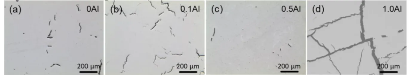
The optical microscopy images of the top surface of all samples are displayed in Fig. 1. Compared to the original 0Al sample, the amounts of Al addition yield different effects towards hot cracking behaviour. Firstly, the crack density increases without a change in crack size when a little Al is introduced in the 0.1Al sample. As the Al content increases to 0.5Al, the crack density drops drastically. Lastly, for the 1.0Al sample, both the crack density and its size increase significantly, producing a highly fragmented sample. Based on the examination over an area of 100 mm2, the crack
densities are determined to be ~10.0 mm-2 for 0Al, ~32.2 mm-2 for 0.1Al, ~2.7 mm-2 for
0.5Al and ~12.4 mm-2 for 1.0Al respectively. It should be noted that all the three
AlxCoCrFeNi samples in the current work were made via blended powders. Though,
this has the advantage of quick assessment for compositional suitability towards AM processes, chemical homogeneity could not truly be guaranteed. Compared to the repeated melting procedures used in arc melting to ensure chemical homogeneity, localised melt pools in AM have limited melt volume and melt duration, hence they may have less chemical homogeneity. At least for the current work, a few confined regions of pure Al particles in 0.5Al were detected by SEM-EDS. Chemical analysis via inductively coupled plasma optical emission spectrometry (ICP-OES) was conducted to confirm the compositions, Table 1. Since 0.1Al, 0.5Al and 1.0Al samples were fabricated via powder blending between the same pre-alloyed CoCrFeNi and pure Al powders, only 0Al and 0.5Al samples were examined for verification. Besides all main elements that are very close to their prescribed values, a minor amount of silicon is detected as impurities. It should be noted that the current study is not attempting to produce “pure” or single-phase HEAs, rather it focuses on hot cracking prevention measures on materials that are prone to hot cracking made via AM.
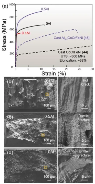
The tensile properties of all samples and their as-cast counterparts, taken from the literature are plotted in Fig. 2(a). Since sample 1.0Al was highly fragmented, no tensile data was recorded. Comparing to the as-cast CoCrFeNi reference material taken from the literature, the ultimate tensile strength (UTS) value of 0Al increased by ~300 MPa but its elongation dropped by 26% from ~38% to ~12% due to the presence of hot
1 2 3 4 5 6 7 8 9 10 11 12 13 14 15 16 17 18 19 20 21 22 23 24 25 26 27 28 29 30 31 32 33 34 35 36 37 38 39 40 41 42 43 44 45 46 47 48 49 50 51 52 53 54 55 56 57 58 59 60
cracks [38]. For 0.1Al, the increased crack density rendered it with virtually no ductility (~2% in elongation) and a low UTS of ~520 MPa. As for 0.5Al, its strength also increased by ~300 MPa while the elongation only dropped by 13% from ~23% to ~10% (as compared to 26% by the 0Al sample) [39]. This indirectly reflected on the crack minimization in sample 0.5Al. It is reported that “built-in flaws” such as porosity and cracks have little influence on strength but huge effects on ductility for AM-built samples [40]. Therefore, with more homogeneous elemental distributions, the ductility of 0.5Al is expected to be significantly higher compared to the current result. However, since this work only aims to elucidate the mechanisms for preventing hot cracking, the 0.5Al sample is sufficient for this purpose. The tensile tests were conducted perpendicular to the sample’s building direction and the fractured surfaces of the tensile specimens are shown in Fig. 2(b) to 2(d). The 0Al sample is omitted here because its fracture surface is very similar to 0.1Al, and it has been reported previously [11]. Unsurprisingly, the fracture surface of 0.1Al material is mostly smooth, indicating the presence of extensive hot cracks as shown in the enlarged image in Fig. 2(b). The enlarged view shows the smooth surface indicating the presence of liquid film at the last stage of solidification, which is a typical hot cracking feature [12]. For 0.5Al, ductile fracture with abundant dimples is frequently observed. High amounts of plastic deformation activities should have occurred during the tensile test. For 1.0Al, brittle fracture in staircase-like form is present. The surfaces of these brittle fractures are smooth and flat, and they do not resemble the morphology of dendrites.
3.2 Phase constitutions and viscosity values
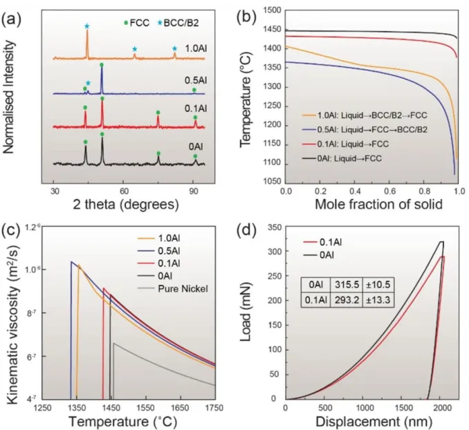
Before examining any potential segregation events, the phase constitution of the above-mentioned alloys should be clarified. As shown in Fig. 3(a), consistent with previous literature, when the Al content is low, AlxCoCrFeNi forms a pure face-centred
cubic (FCC) phase (disordered, with A1 structure), as is the case for samples 0Al and 0.1Al. When the Al content continues to increase, a mixture of body-centred cubic (BCC) phase (either disordered A2 or ordered B2) and FCC phase will be present, such as observed in alloy 0.5Al. Finally, when the Al content exceeds a certain threshold (x ≈ 0.9), the material will be a single BCC phase [41, 42]. It is worth noting that XRD alone could not distinguish the A2 or B2 structures here, possibly due to the
1 2 3 4 5 6 7 8 9 10 11 12 13 14 15 16 17 18 19 20 21 22 23 24 25 26 27 28 29 30 31 32 33 34 35 36 37 38 39 40 41 42 43 44 45 46 47 48 49 50 51 52 53 54 55 56 57 58 59 60 61
similar scattering amplitudes of the related ordered atoms. Therefore, further examination by other techniques was needed to differentiate and quantify the possible phases present within alloy 0.5Al. The three major constituent phases will be hereafter referred to as FCC, BCC (for A2) and B2, in accordance with previous literature [43, 44]. Besides the presence of both FCC and B2/BCC phases, 0.5Al sample shows a preferred (001) crystallographic texture. This will be confirmed by the EBSD maps later. It is found that while there is a change in texture, the grain size remains similar to alloys 0Al and 0.1Al. Solidification path data calculated under the Scheil non-equilibrium condition was also obtained, Fig. 3(b). For 0Al and 0.1Al, the alloys exist in a single FCC phase and their solidification range (𝛥𝑇 = 𝑇𝑙𝑖𝑞𝑢𝑖𝑑𝑢𝑠− 𝑇𝑠𝑜𝑙𝑖𝑑𝑢𝑠) are ~19°C and ~46°C, respectively. The alloy 0.5Al solidifies as FCC first before B2/BCC starts to appear. It has a 𝛥𝑇 value of ~289°C. Lastly, 1.0Al solidifies mainly as B2/BCC. The FCC phase is supposed to emerge near the end of solidification. However, experimentally, no FCC phase was detected in XRD or EBSD in alloy 1.0Al. This is either due to low volume fraction or to the fast solidification rate in SLM processing, which suppresses its formation. In terms of its 𝛥𝑇, it has the largest value of ~293°C among all samples.
Another important factor that influences hot cracking susceptibility is liquid backfilling, which is the ability of liquid/semi-solid materials to refill any new opening (porosity or cracks) below them. It is closely related to the alloy’s kinematic viscosity values. Viscous materials are harder to flow into openings, and they are thus more prone to cracking. The kinematic viscosity values obtained from Thermo-Calc are plotted in Fig. 3(c), and the data of pure Ni is inserted as a representative reference for the 4 transition elements. Pure Al is known to have a very low viscosity near its melting point and it is therefore not used to compare to the current alloy system [45]. Compared to pure Ni, the HEAs’ viscosities are almost twice of its value, making liquid backfilling more difficult. It is observed that at any fixed temperature, the viscosities of the alloys decrease with the addition of Al. However, the viscosity values increase sharply as the temperature drops. As a result, the viscosities near the respective melting points are higher as the Al content increases which is supposed to make the alloys more prone to hot tearing. One interesting phenomenon in the 0.1Al alloy that is rarely reported in the literature, is its material softening behaviour compared to the reference alloy 0Al. To access the hardness values without the influence of prevalent cracks,
1 2 3 4 5 6 7 8 9 10 11 12 13 14 15 16 17 18 19 20 21 22 23 24 25 26 27 28 29 30 31 32 33 34 35 36 37 38 39 40 41 42 43 44 45 46 47 48 49 50 51 52 53 54 55 56 57 58 59 60
nanoindentation technique was adopted and representative results of the 0Al and 0.1Al samples are shown in Fig. 3(d). In total, 16 indentations were placed upon each sample and the registered maximum load for alloy 0Al is 315.5 ± 10.5 mN and alloy 0.1Al is 293.2 ± 13.3 mN. Thus, a minor amount of Al addition of only 1.2% within the FCC matrix makes the material softer. This decreased load-bearing ability for material 0.1Al is also expected to promote more hot cracks as compared to the reference 0Al sample. Compared to the 0Al and 0.1Al samples, the nanoindentation results of the 0.5Al sample (317.2 ± 17.5 mN) deviate a lot more due to the presence of the hard B2/BCC phases. Moreover, its average hardness value is very close to that of the base 0Al material. Therefore, the reduction of hot cracks cannot be ascribed to the load-bearing ability variations.
3.3 Overall grain morphologies
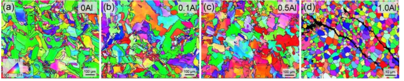
Overview EBSD maps for the 4 samples are shown in Fig. 4. It is found that the average grain size for alloys 0Al, 0.1Al and 0.5Al is very similar to one another, ~60 μm in diameter. Compared to sample 0Al and 0.1Al, alloy 0.5Al indeed shows a preferred (001) crystallographic texture parallel to the building direction as suggested by the XRD result, but the overall HAGB density remains comparable. The change in crystallographic texture is expected to be caused by the variation in the melt pool morphology [2]. However, the exact formation mechanism is not clear yet. All cracks observed in the first 3 samples are aligned along the HAGBs, suggesting the existence of hot cracks. As for alloy 1.0Al, its cracking nature seems to be slightly different compared to that observed in the other samples. It is not solely intergranular, but a mixture of intergranular and intragranular. The formation mechanisms for these observations will be further explained in the discussion section.
3.4 Interdendritic microstructures of Al0.5CoCrFeNi
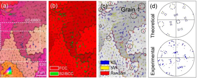
To better understand the crack minimization mechanism of sample 0.5Al, its grain morphology and phase distribution surrounding the interdendritic/grain boundaries regions were examined to a greater detail as shown in Fig. 5. The EBSD map was
1 2 3 4 5 6 7 8 9 10 11 12 13 14 15 16 17 18 19 20 21 22 23 24 25 26 27 28 29 30 31 32 33 34 35 36 37 38 39 40 41 42 43 44 45 46 47 48 49 50 51 52 53 54 55 56 57 58 59 60 61
taken perpendicular to the building direction. Areas used for EDS and CC-EBSD later are highlighted by white dotted lines, Fig. 5(a). All the B2/BCC phases are found to be located in the interdendritic regions or at grain boundaries of the parent FCC grains, Fig. 5(b). The dendritic size of ~1.5 μm is similar to the SLM-built CoCrFeNi [11]. From the thermodynamic simulation, it is concluded that the solubility of Al within the parent FCC matrix reduces with decreasing temperature during solidification. Al is thus partitioned into the interdendritic regions and segregated to the grain boundaries where hot cracking is prone to occur. These Al-enriched regions will then form the B2/BCC phase, owing to the locally altered composition and resulting thermodynamic driving forces [46-48]. The EBSD map reveals an average grain diameter of the B2/BCC phase of ~0.35 μm, and they are observed to have different types of morphologies accommodating the adjacent FCC dendrites/grains. It is observed that within a single FCC grain, the B2/BCC phases do not follow the same crystallographic orientation among themselves. This is possibly due to the different sets of crystallographic orientation relationships (ORs) that they are holding with their respective parent grains. To examine if there is any specific crystallographic OR existing between the parent FCC and B2/BCC product phases, 5 ORs were selected for inspection, namely, the Bain ({100}γ//{100}α, <100>γ//<110>α), the Kurdjumov-Sachs (KS) ({111}γ//{110}α, <110>γ//<111>α), the Nishiyama-Wasserman (NW)
({111}γ//{110}α , <112>γ//<110>α), the Greninger-Trojano (GT) ({111}γ//{110}α,
<123>γ//<133>α) and the Pitsch ({100}γ//{110}α, <110>γ//<111>α) OR (γ: fcc phase, α:
B2/BCC phase) [49]. When limiting the plane and direction rotational range to 2.5°, it is found that only KS, NW and GT ORs were detected while the rest were found to be random phase boundaries. As the combination of KS and NW ORs could successfully represent all GT ORs, only KS, NW and random phase boundaries are displayed in Fig. 5(c).
It is known that the presence of stress fields can affect the formation of certain OR variants [50], hence it is interesting to examine whether specific ORs or OR variants between the B2/BCC and FCC phases emerge. To clarify this question, the preferred variant selection from FCC to BCC is discussed in the following. If the presence of specific ORs is mainly attributed to the presence of residual stresses, there should be a preferred variant selection during the phase transformation. To test this, all the theoretically possible 24 variants of the KS relationship and 12 variants of NW
1 2 3 4 5 6 7 8 9 10 11 12 13 14 15 16 17 18 19 20 21 22 23 24 25 26 27 28 29 30 31 32 33 34 35 36 37 38 39 40 41 42 43 44 45 46 47 48 49 50 51 52 53 54 55 56 57 58 59 60
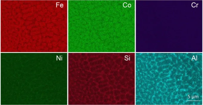
relationships were plotted in a (001) pole figure with respect to the FCC parent grain (Grain 1 in Fig. 5(c)), as shown in Fig. 5(d). All experimental data of the B2/BCC grains within the original parent grain were also plotted separately under the same condition. We find a close resemblance between the theoretical and experimental data, suggesting that there is no specific variant selection for the ORs. It is thus believed that the presence of residual stresses did not play a major role in the formation of KS or NW ORs in the present material. With this, the residual stress content should not be affected much by the ORs formations in this case. EDS mapping was also conducted to capture the elemental distribution across different phases, Fig. 6. Fe and Co are found to be enriched in the dendritic regions and partition into the parent FCC phase. Cr remains mostly homogeneous across the whole mapping area. The remaining elements Ni, Si and Al co-segregate into the interdendritic regions, forming the B2/BCC phase. The quantitative chemical compositions are listed in Table 2 together with the TEM results. Compared to the AM-built Ni-base superalloys, the current 0.5Al alloy seems to have a higher tolerance of Si without having extensive hot cracks [12, 26, 51]. Since hot cracking only occurs along HAGBs at the end of solidification, where Al-enriched B2/BCC phases are present, a closer examination of these B2/BCC phases is thus needed.
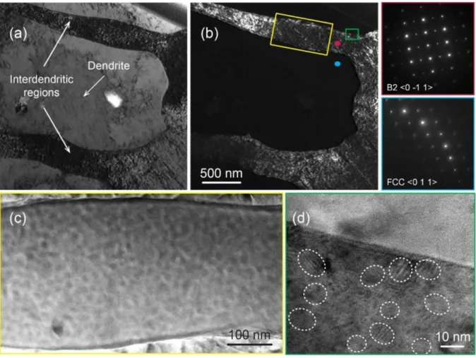
Bright and dark field TEM images of the dendritic and interdendritic areas are shown in Fig. 7(a) and 7(b) with their respective SAED patterns framed in red and blue. The dendrite has a width of ~1.5 μm, which is consistent with those observed from Fig. 5(a). The presence of B2 phase within the interdendritic area is confirmed by the superlattice spots in the diffraction pattern along its <011> zone axis after tilting. An enlarged view of the dendritic arm is shown in Fig. 7(c). Within this region, a periodic and spinodal-like compositional modulation is observed. There seem to be two nano-sized phases homogeneously distributed in these Al-enriched interdendritic regions, which is representative for spinodal decomposition [52-54]. Moreover, it is reported from previous studies on cast samples of AlxCoCrFeNi and AlxCoCrCuFeNi HEAs with
high Al content (x=1.0), that spinodally decomposed B2 and BCC phases are indeed present [55-58]. The HRTEM image in Fig. 7(d) shows a closer view of the FCC and B2/BCC interface. Fringe patterns (circled in white) were found in the interdendritic region, which are believed to be Moiré fringes, a phenomenon which occurs when electrons that travel through an interface region between two slightly misaligned
1 2 3 4 5 6 7 8 9 10 11 12 13 14 15 16 17 18 19 20 21 22 23 24 25 26 27 28 29 30 31 32 33 34 35 36 37 38 39 40 41 42 43 44 45 46 47 48 49 50 51 52 53 54 55 56 57 58 59 60 61
lattices, either due to different lattice constants or due to slightly different orientations [59]. Due to their nano-scale sizes (~10 nm) and overlapping nature, precise TEM-EDS differentiation of the two decomposed phases is not possible. However, the elemental distribution between the dendritic and interdendritic regions was recorded, and they are presented in Table 2 together with the SEM-EDS results. To get the quantitative chemical compositions of all phases within the current 0.5Al alloy, APT studies were carried out.
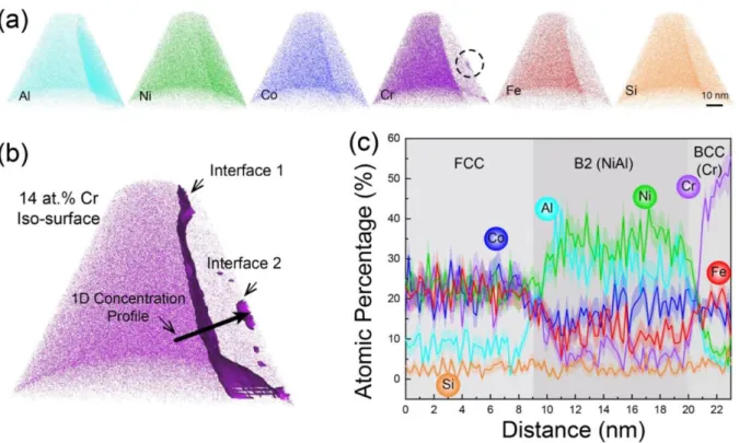
The atomic-scale elemental reconstruction for all elements and phases within the tip is shown in Fig. 8(a). A phase interface can be discerned inclining about 15° from the vertical axis to the right. Moreover, small clusters of Cr-enriched regions are observed on the rightmost side of the Cr reconstruction (circled in black). To reveal all phases with better clarity, an iso-surface of 14 at.% Cr was computed, as shown in Fig. 8(b). The value of 14 at.% is chosen based on the midpoint of Cr concentrations surrounding interface 1. Three distinct regions were identified within the single APT tip. A 1D concentration profile spanning across all three phases with a cylinder diameter of 10 nm is plotted in Fig. 8(c). Interface 1 is characterized by a transition from the primary FCC phase to a Ni and Al enriched phase. Since Ni and Al have similar atomic concentrations, and they make up more than ~65 at.% of the compound, thus it can be identified to be the NiAl phase with an ordered B2 structure. As for interface 2, when the elements get closer to the interface from the NiAl phase, it suggests an uphill diffusion pattern for Cr. A similar phenomenon of Cr segregation in the form of a spinodal decomposition has been reported in several alloys such as FeCr, FeCrCo, AlCoCrFeNi, CoCrFeNiMn [47, 55, 60, 61]. Given its high atomic percentage of Cr (~60 at.%), the third phase is identified to be a disordered BCC Cr-based solid solution. Since the lattice parameters of B2(NiAl) and BCC(Cr) are both ~2.88 Å at room temperature, it is plausible to assume that they are coherent [62, 63]. This is also confirmed by the TEM study that only a single set of diffraction patterns was observed from the <011>B2/BCC zone axis in the interdendritic area, as shown in Fig. 7(b). Till
now, all the phases present in alloy 0.5Al have been identified, their formation sequence and contributions towards the minimization of hot tearing will be discussed in the following section.
1 2 3 4 5 6 7 8 9 10 11 12 13 14 15 16 17 18 19 20 21 22 23 24 25 26 27 28 29 30 31 32 33 34 35 36 37 38 39 40 41 42 43 44 45 46 47 48 49 50 51 52 53 54 55 56 57 58 59 60
4. Discussion
4.1 Abnormal hot cracking behaviour of Al0.5CoCrFeNi
In the current study, with the addition of Al to the CoCrFeNi matrix, the hot cracking susceptibility shows a non-linear trend. According to the solidification range theory, the hot cracking propensity should be proportional to the solidification range 𝛥𝑇 and this is not entirely true for the current alloy series. As compared to the reference 0Al sample, alloy 0.1Al shows an increment in solidification range of 27°C and this indeed leads to an increase in crack number density (by about three times to be exact), consistent with the theory. However, as for the 0.5Al sample, its solidification range is nearly 15 times compared to the reference 0Al sample, yet its crack number density decreased by more than three times. With a similar solidification range as alloy 0.5Al, the 1.0Al sample has the highest crack number density, instead. Therefore, these experimental observations suggest that the solidification range theory is most likely only effective for alloy species which consist of the same phase and have very similar chemical compositions. The same phenomenon has been observed in Ni-based superalloys. For similar chemical compositions but a small adjustment of the Ti content in IN625, a shorter solidification range reduces the alloy’s hot cracking susceptibility [19]. However, for alloys with vastly different compositions, such as IN792 and CM247, the solidification range theory breaks down [17]. This explains why the solidification range theory is not really useful for the current 0.5Al and 1.0Al samples.
Built upon the solidification range theory, the RDG model points out the importance of liquid viscosity values towards hot crack minimization through liquid backfilling [16]. Generally, a more viscous liquid is more prone to hot tearing as it is more difficult to flow and heal any existing porosity/crack. However, based on the viscosity data shown in Fig. 3(c), the rank of all materials by their viscosity values near their solidification temperatures is 0.5Al > 1.0Al > 0.1Al > 0Al. This suggests that alloy 0.5Al should have the highest number of hot cracks followed by 1.0Al, 0.1Al and 0Al samples. The viscosity data might have played a role in the increase in cracks for alloys 1.0Al and 0.1Al, it is certainly not the reason for the crack reduction in the 0.5Al sample. Moreover, through a closer examination of all the phases present in each alloy, it is found that material 1.0Al is made of the hard and brittle B2 and BCC phases, Fig. 3(a).
1 2 3 4 5 6 7 8 9 10 11 12 13 14 15 16 17 18 19 20 21 22 23 24 25 26 27 28 29 30 31 32 33 34 35 36 37 38 39 40 41 42 43 44 45 46 47 48 49 50 51 52 53 54 55 56 57 58 59 60 61
From its fracture surface shown in Fig. 2(d), we concluded that the material failed by cold cracking (solid-state brittle cracking due to residual stresses). This explains why the fracture pattern is characterized by a mixture of intergranular and intragranular cracks as shown in Fig. 4(d). Despite all these attempts, none of the previous theories could explain the phenomenon of hot-crack reduction in alloy 0.5Al. In order to answer this question, the phase formation sequence in its interdendritic/grain boundary regions needs to be clarified.
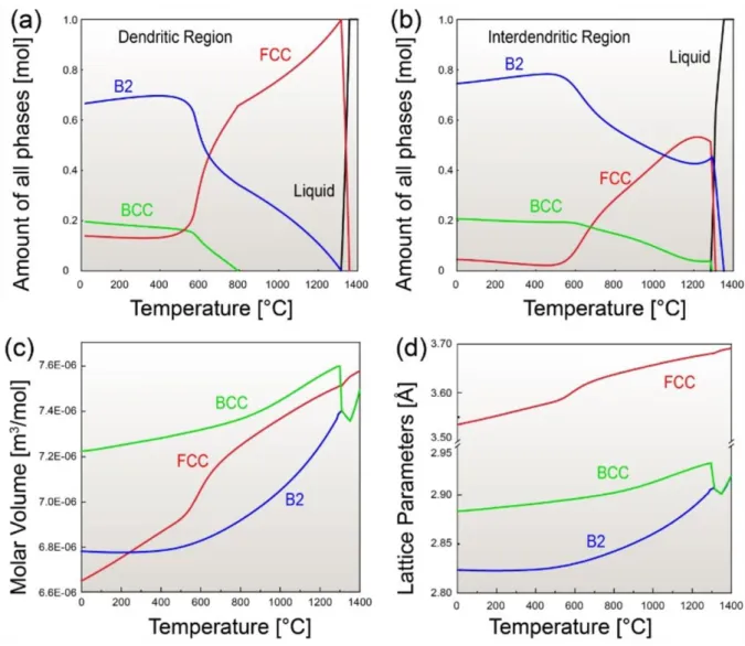
4.2 Segregation driven phase transformation and molar volume expansion
To probe the sequence of phase formations in the 0.5Al sample, the equilibrium phase fractions were calculated with both the dendritic and interdendritic compositions (using the TEM compositions in Table 2) via Thermo-Calc. It is noted that calculations made under such conditions are expected to be slightly different from the actual AM case. However, after comparing with their respective Scheil non-equilibrium calculations, the phase formation sequence remains to be the same. Also, the equilibrium phase fraction calculations could reveal any potential solid-state phase transformation information which the Scheil simulations could not. As shown in Fig. 9(a), for the dendritic region, only FCC is present during solidification. Under subsequent cooling, the primary FCC is supposed to transform into B2 and BCC phases. However, in reality, the dendritic regions only consist of the primary FCC phase. This is possibly because the B2/BCC phase is kinetically suppressed by the fast cooling rate during the AM process. As for the interdendritic regions (Fig. 9(b)), when the Al content increases from 5.69 wt.% to 7.77 wt.%, the primarily solidified phase changed to the B2 phase. Though, the FCC phase appears as well after B2 during solidification, it is soon transformed into B2 and BCC phases. This explains the unique ORs observed in Fig. 5(c), where a small number of B2/BCC grains, both at the interdendritic and grain boundary regions (highlighted by dotted black circles), do not follow any of the existing specific ORs. These grains should be the result of the directly solidified B2 phase as predicted by Thermo-Calc in Fig. 9(b) and no specific ORs should be present during solidification. It is noted though, that the Thermo-Calc simulation in Fig. 9(b) seems to have overpredicted the amount of directly solidified B2 phase as it takes inputs of the final composition of the interdendritic regions at room temperature. Thus, the actual
1 2 3 4 5 6 7 8 9 10 11 12 13 14 15 16 17 18 19 20 21 22 23 24 25 26 27 28 29 30 31 32 33 34 35 36 37 38 39 40 41 42 43 44 45 46 47 48 49 50 51 52 53 54 55 56 57 58 59 60
amount of directly solidified B2 phase in Fig. 5(c) is definitely lower than ~40% as predicted in Fig. 9(b). Besides the directly solidified B2 phase, the remaining liquid forms the FCC phase which will turn into the B2 phase through a solid-state transformation. This creates those KS and NW ORs that are detected in Fig. 5(c). For the transformed B2 phase between two parent FCC grains, they could only obey the specific OR with one of them. Therefore, most of the B2/BCC grains located at the FCC grain boundaries always have a mixture of random (red) and KS/NW (blue/yellow) phase boundaries. During the cooling stage after solidification, the B2 phase will then decompose into the B2 and BCC mixture through a spinodal process which was identified by the previous TEM and APT studies, Fig. 7(c) and Fig. 8(b). It is expected that the appearance of directly solidified B2 should help to break up the continuous liquid film between adjacent grains during solidification, which will in turn facilitate bridging and prevent hot tearing.
One factor that is often neglected when investigating the root cause of hot cracking is the change of the molar volume at the interdendritic/grain boundary regions during and after the solidification process. In thermodynamic models, it is typically computed as [64]:
𝑉𝑚(𝑇) = 𝑉0exp(∫ 3𝛼𝑑𝑇 𝑇 𝑇0
) + 𝛥𝑉𝑚𝑚𝑎𝑔(𝑇) Eq. 1
where 𝑉𝑚(𝑇) is the molar volume at a given temperature 𝑇, 𝑉0 is the molar volume at a reference temperature 𝑇0, 3𝛼 is the thermal expansion coefficient of a phase in its
nonmagnetic state, and 𝛥𝑉𝑚𝑚𝑎𝑔(𝑇) is the magnetic contribution to the molar volume. If there is a sharp reduction of a given phase’s molar volume as the temperature decreases, larger residual stresses will be induced due to thermal contraction (higher propensity to hot cracking) and vice versa. The molar volume values of all three phases calculated using the interdendritic composition are plotted with respect to temperature in Fig. 9(c). At room temperature, the BCC phase has the highest molar volume value followed by B2 and FCC. The biggest molar volume change is created by the spinodal decomposition from B2 to BCC. They are thus believed to effectively counteract the thermal residual strains built upon the HAGBs during the solidification process. Therefore, the likelihood of hot tearing is minimized. The sharp increment of the molar volume for the BCC phase is caused by the strong antiferromagnetic
1 2 3 4 5 6 7 8 9 10 11 12 13 14 15 16 17 18 19 20 21 22 23 24 25 26 27 28 29 30 31 32 33 34 35 36 37 38 39 40 41 42 43 44 45 46 47 48 49 50 51 52 53 54 55 56 57 58 59 60 61
property of pure Cr [65]. The𝛥𝑉𝑚𝑚𝑎𝑔(𝑇) component for pure Cr is rather significant and it also increases with temperature due to its electronic spin fluctuation activities [64]. Given the molar volume values, their respective lattice parameters could also be determined via Equation 2, and they are plotted in Fig. 9(d),
𝛼 = √(𝑉3 𝑚/(𝑁𝐴/𝑁𝑜.𝑎𝑡𝑜𝑚𝑠)) Eq. 2
where 𝛼 is the lattice parameter, 𝑁𝐴 is Avogadro’s constant (6.022×10²³ mol-1) and
𝑁𝑜.𝑎𝑡𝑜𝑚𝑠 is the number of atoms per lattice (2 for B2/BCC and 4 for FCC). The
calculated lattice parameters near the room temperature are 𝑎𝐹𝐶𝐶 ~3.53 Å, 𝑎𝐵2 ~2.82 Å and 𝑎𝐵𝐶𝐶 ~2.88 Å. They are in close resemblance to experimentally determined
lattice parameters by XRD, which are 𝑎𝐹𝐶𝐶 of ~3.59 Å and 𝑎𝐵𝐶𝐶/𝐵2 of ~2.87 Å. The EBSD map conducted over an area of 15000 μm2 with a step size of 50 nm has
revealed a ~1.3% area fraction of B2/BCC phase in total. Yet this value is expected to be an underestimation due to the EBSD resolution, any B2/BCC phase smaller than 100 nm will not be identified by the EBSD map. The exact amount is difficult to be estimated though. Irrespective of this experimental constraint, one may suspect that their volume fraction is too low to cause an impact on the reduction of hot cracks. However, it should be recalled that the B2 and BCC phases only exist in the interdendritic and grain boundary regions where hot cracking is most likely to initiate. In other words, if the residual stresses at these regions could be effectively relaxed, the overall hot cracking susceptibility of the material should be improved.
4.3 Residual stress relaxation
To validate the previous hypothesis, cross-correlation CC-EBSD experiments were conducted on the 0.5Al sample, allowing to probe the residual stress distribution among different microstructural features. [66]. Compared to the conventional residual stress characterization techniques such as destructive image correlation (hole-drilling) and conventional X-ray diffraction, CC-EBSD has orders of magnitude better spatial resolution (in the order of 1003 nm3) and it maps, together with the residual stress
tensor, also the local microstructure [67, 68]. An area of 15 × 20 μm2 (shown previously
in Fig. 5(a)) was mapped with a step size of 50 nm to acquire diffraction patterns with
1 2 3 4 5 6 7 8 9 10 11 12 13 14 15 16 17 18 19 20 21 22 23 24 25 26 27 28 29 30 31 32 33 34 35 36 37 38 39 40 41 42 43 44 45 46 47 48 49 50 51 52 53 54 55 56 57 58 59 60
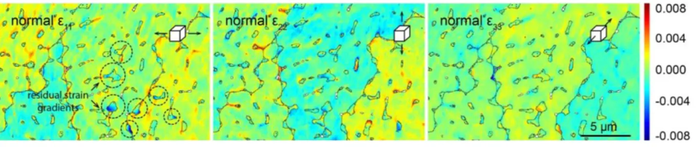
high pixel resolution. The residual strain values are obtained by comparing all diffraction patterns within one grain with a reference pattern from the same grain which is assumed to be strain-free. Note that this assumption usually is not true, thus, the determined strain value for every point is biased by the strain value of the reference point. As for the reference pattern, we selected the one inside of the respective grain with the highest indexing confidence value. In order to reduce the effect of orientation gradients within grains an extra step of “remapping” was performed [35]. The residual stresses can be calculated from the measured elastic strains if the material’s elastic constants are known. The lateral distributions of the obtained normal strain tensor components are plotted in Fig. 10. We find that the majority of the normal residual strains are confined to areas surrounding the B2/BCC grains. Positive values (red in colour) indicate a tensile strain and negative values (blue in colour) show a compressive strain. All the parent FCC grains are shown to be greenish in colour, which indicates no or very low residual strain levels. As for the B2/BCC grains, they are highly strained with an absolute strain value up to 0.08. Moreover, it is found that the residual strain within each B2/BCC grain is seldom uniform. There is always a strain gradient inside the B2/BCC grains as highlighted by the black dotted circles. This indicates non-uniform deformation due to residual stresses probably originating from solidification. The normal strains following other directions show similar behaviors. To better capture the plastic activity due to residual stresses between the different phases, the geometrically necessary dislocations (GNDs) map is calculated and plotted in Fig. 11. Similar to the normal strains, the B2/BCC grains have a higher content of dislocations. The parent FCC grains mostly have a GND density of ~1014,
which is a typical value for FCC materials [69]. The GND density in the B2/BCC grains is about one order of magnitude higher compared to the FCC grains. This is because during the solidification process, the thermal contraction of the FCC phase leads to tensile forces acting on the interdendritic/grain boundary regions. During further cooling, the decomposition of the B2 phase into the B2 and BCC mixture creates a molar volume expansion. Therefore, compressive forces are built up within the B2/BCC grains which are reflected by the blue colours in Fig. 10. These compressive forces are beneficial towards the residual stress minimisation which improves the hot cracking susceptibility of the material. Moreover, it is found that the B2/BCC grains distribute quite asymmetrically in the microstructure (regular oscillations along the
1 2 3 4 5 6 7 8 9 10 11 12 13 14 15 16 17 18 19 20 21 22 23 24 25 26 27 28 29 30 31 32 33 34 35 36 37 38 39 40 41 42 43 44 45 46 47 48 49 50 51 52 53 54 55 56 57 58 59 60 61
FCC grain boundaries). The asymmetric expansion forces would then create shear stresses which may subsequently cause the formation of GNDs along the B2/BCC and FCC interfaces shown in Fig. 11. The B2/BCC grains act as an effective residual mechanical work absorber and thus minimize the detrimental effect of residual stress/strain towards hot cracking. It should be noted though, since the current material is processed under the rapid solidification condition, high residual stresses occur all over and it is unlikely to find a “strain-free” reference pattern. Therefore, at best, the CC-EBSD technique only provides a qualitative comparison between residual stress levels among different microstructures. To confirm the CC-EBSD results and obtain a quantitative and reference-free residual strain distribution around grain boundaries, FIB-DIC ring-core milling has been adopted as a reference technique as shown in Fig. 12.
The FIC-DIC ring-core milling technique was originally proposed to determine the planar residual stress levels in thin coatings [70]. It uses the digital image correlation technique to track the dimensional changes due to stress relaxation [71]. In this work, random HAGBs of both the 0.5Al and 0Al samples were selected to validate the effectiveness of stress relaxation by the B2/BCC grains. For the 0.5Al sample, a major vertical HAGB is selected which contains multiple B2/BCC grains, Fig. 12(a). As for the 0Al sample, a major horizontal HAGB is detected based on a rough EBSD mapping. The detailed post-milled EBSD graph of the region is presented in Fig. 12(e). The residual strains for both samples were determined across the vertical and horizontal fiducial markers which are ~5 μm apart. Both samples reached a milling depth of ~3 μm (30% of the ring diameter). It is reported from previous literature that a milling depth ≥20% of the ring diameter should sufficiently relax the pillar to provide reliable results [36, 37]. The FIB-DIC results for both samples are displayed in Fig. 13. For the single-phase 0Al sample, as the milling depth increases, there is a general shrinking phenomenon for the pillar as shown by the blue curves. The strain values were found to be negative along both horizontal and vertical directions. This suggests that the current HAGB region was subjected to tensile residual strains before the milling. A large strain value of around -0.006 was detected along the vertical direction of the 0Al sample. This indicates a large tensile strain acting perpendicularly to the horizontal HAGB shown in Fig. 12(e). Contrarily, the 0.5Al sample expands upon milling instead of shrinking (orange curves). Also, the absolute values of the residual strains of 0.5Al
1 2 3 4 5 6 7 8 9 10 11 12 13 14 15 16 17 18 19 20 21 22 23 24 25 26 27 28 29 30 31 32 33 34 35 36 37 38 39 40 41 42 43 44 45 46 47 48 49 50 51 52 53 54 55 56 57 58 59 60
are considerably lower compared to the 0Al sample. Of the two analyzed directions, the horizontal direction shows a larger strain of ~0.0013. Once again, it acts perpendicularly to the major vertical HAGB in Fig. 12(a). Therefore, there is a distinct difference in the residual strain behaviors of the two samples. To confirm this, a second test was conducted on each sample. The same pillar shrinkage behavior was observed for 0Al with roughly the same magnitudes. However, for 0.5Al, in areas where the B2/BCC content was below the detection limit of EBSD, a slight shrinkage was observed with an absolute value of ~0.1. Therefore, it is concluded that the B2/BCC phase quantity will determine the overall residual strain states surrounding the grain boundaries in 0.5Al. Ideally, the residual stresses in all 4 samples probed in the current study could have been fully analyzed. However, it should be also noted that the 0.1Al and 1.0Al samples had already undergone such extensive hot cracking, that the original residual stresses had been essentially relieved during the crack initiation and propagation stages. Therefore, only the residual stress levels of the base material 0Al and the special case of the 0.5Al alloy were measured and analyzed.
Under normal conditions (the single-phase 0Al reference sample), the grain boundaries are always the last to solidify due to their lower coalescence temperatures. With high tensile residual stresses caused by thermal contraction and insufficient load-bearing grain boundaries, the liquid or semi-solid film at the end of solidification is prone to hot cracking. However, through proper segregation engineering, the properties of the lastly solidified liquid film could be successfully engineered to prevent this from happening. For the 0.5Al sample, during the initial solidification process, Al is segregated into the interdendritic/grain boundaries regions to form a continuous liquid film, Fig. 14(a). Upon further cooling, the B2/BCC phases will appear as isolated islands while high tensile residual strains are built up due to thermal contraction, Fig. 14(b). Under the combined effects of molar volume expansion and plastic deformation, they could effectively relieve the residual stresses/strains, Fig. 14(c). Under certain instances, with a sufficient percentage of the B2/BCC phases, the large residual tensile strain could even be transformed into a small compressive state as shown in Fig. 14(d). It should be noted though, that the amount of these B2/BCC phases should be carefully controlled. By investigating about 8 remaining hot cracks in 0.5Al, it is found that there is a continuous line of the B2/BCC phases along the cracks. This is due to the chemical heterogeneity caused by powder mixing where the Al particles
1 2 3 4 5 6 7 8 9 10 11 12 13 14 15 16 17 18 19 20 21 22 23 24 25 26 27 28 29 30 31 32 33 34 35 36 37 38 39 40 41 42 43 44 45 46 47 48 49 50 51 52 53 54 55 56 57 58 59 60 61
were enriched at certain localized regions. Since the B2/BCC phases are highly brittle, when they exist in a continuous film, they will facilitate crack initiation and propagation instead of acting as strain absorbers. It also indirectly demonstrates the advantage of using pre-mixed powder to examine the effect of compositional variation towards hot cracking in AM. Therefore, an Al content slightly smaller than 0.5 could potentially remove all remaining hot cracks. However, since the current work is mainly focused on elucidating the mechanism of hot-cracking prevention, the 0.5Al sample provides a reasonable and conclusive example for this purpose.
4. Conclusions
The present work investigated the mechanism of hot cracking minimization through grain boundary segregation engineering for an existing CoCrFeNi high-entropy alloy made via laser-powder bed fusion. Varying molar amounts of Al (x=0.1, 0.5 and 1.0 for AlxCoCrFeNi) were added to the base material to illustrate the importance of
interdendritic/grain boundary phase constitutions to prevent hot cracking. The main findings of the present work are summarized below.
Compared with the SLM-built CoCrFeNi sample, more cracks were found in the Al0.1CoCrFeNi and Al1.0CoCrFeNi samples. However, the cracking mechanisms
for these two samples are different.
For Al0.1CoCrFeNi, all hot cracks are intergranular, similar to the CoCrFeNi
sample. The slight increase for critical temperature range (𝛥𝑇 = 𝑇𝑙𝑖𝑞𝑢𝑖𝑑𝑢𝑠− 𝑇𝑠𝑜𝑙𝑖𝑑𝑢𝑠) and kinematic viscosity values as predicted by the thermodynamic
simulations could facilitate the crack increment. Moreover, the decrease in its load-bearing capability, or material softening as evidenced by the nano-indentation experiment, makes crack initiation and propagation easier.
As for the Al1.0CoCrFeNi sample, in addition to the influence from 𝛥𝑇 and
kinematic viscosity, the primary solidified phase is the brittle B2 phase. As a result, both intergranular and intragranular cold cracks were identified in Al1.0CoCrFeNi.
In contrast to the Al0.1CoCrFeNi and Al1.0CoCrFeNi samples, alloy
Al0.5CoCrFeNi experiences a unique phase formation sequence. During the 1 2 3 4 5 6 7 8 9 10 11 12 13 14 15 16 17 18 19 20 21 22 23 24 25 26 27 28 29 30 31 32 33 34 35 36 37 38 39 40 41 42 43 44 45 46 47 48 49 50 51 52 53 54 55 56 57 58 59 60
solidification, Al firstly partitioned into the interdendritic and grain boundary regions. After the primary B2 solidified, the remaining liquid would form an FCC matrix. This FCC phase then turned into B2 via a solid-state phase transformation. Lastly, the B2 would become a B2 and BCC mixture through a spinodal decomposition.
This special interdendritic/grain boundary microstructure helps to drastically reduce crack density for the Al0.5CoCrFeNi sample. The primarily solidified B2
phase prevents the establishment of a continuous liquid film and assists in dendritic bridging. Together, the B2/BCC grains act as effective mechanical work absorber and reduce the overall tensile residual contents. Given a sufficient content, they could switch the residual strain from a tensile state into a compressive state which is highly beneficial towards reducing hot tearing.
In summary, the current study illustrates a novel approach of using segregation engineering to control the liquid or semi-solid film properties at the end of solidification to prevent hot cracking in metals and alloys fabricated by AM. This approach is envisioned to be particularly helpful towards minimizing stress-induced hot cracks. Together with other existing methods to counteract hot cracking, such as grain refinement and solidification range reduction, it aims to extend our current material tool library and propel further advancements for the field of metal AM technology.
Acknowledgments
This work was partially supported by the Medium-Sized Centre funding scheme awarded by the National Research Foundation, Prime Minister’s Office, Singapore. The authors are grateful to financial support from the French METSA network (FR3507) for APT experiments and to the German Ministry of Education and Research for funding of the “Danish” project under grant number 03XP02154. The authors would also like to acknowledge the help received from H. Zhao and A.K. Da Silva at Max Planck Institut für Eisenforschung for the interpretation of APT and thermodynamic simulation results. 1 2 3 4 5 6 7 8 9 10 11 12 13 14 15 16 17 18 19 20 21 22 23 24 25 26 27 28 29 30 31 32 33 34 35 36 37 38 39 40 41 42 43 44 45 46 47 48 49 50 51 52 53 54 55 56 57 58 59 60 61
References
[1] T. DebRoy, H.L. Wei, J.S. Zuback, T. Mukherjee, J.W. Elmer, J.O. Milewski, A.M. Beese, A. Wilson-Heid, A. De, W. Zhang, Additive manufacturing of metallic components – Process, structure and properties, Progress in Materials Science 92 (2018) 112-224.
[2] Z. Sun, X. Tan, S.B. Tor, C.K. Chua, Simultaneously enhanced strength and ductility for 3D-printed stainless steel 316L by selective laser melting, NPG Asia Materials (2018).
[3] M.S. Pham, B. Dovgyy, P.A. Hooper, C.M. Gourlay, A. Piglione, The role of side-branching in microstructure development in laser powder-bed fusion, Nat Commun 11(1) (2020) 749.
[4] Y.M. Wang, T. Voisin, J.T. McKeown, J. Ye, N.P. Calta, Z. Li, Z. Zeng, Y. Zhang, W. Chen, T.T. Roehling, R.T. Ott, M.K. Santala, P.J. Depond, M.J. Matthews, A.V. Hamza, T. Zhu, Additively manufactured hierarchical stainless steels with high strength and ductility, Nat Mater (2017).
[5] X. Tan, Y. Kok, Y.J. Tan, M. Descoins, D. Mangelinck, S.B. Tor, K.F. Leong, C.K. Chua, Graded microstructure and mechanical properties of additive manufactured Ti–6Al–4V via electron beam melting, Acta Materialia 97 (2015) 1-16.
[6] R. Shi, S.A. Khairallah, T.T. Roehling, T.W. Heo, J.T. McKeown, M.J. Matthews, Microstructural control in metal laser powder bed fusion additive manufacturing using laser beam shaping strategy, Acta Materialia 184 (2020) 284-305.
[7] T. Mukherjee, J.S. Zuback, A. De, T. DebRoy, Printability of alloys for additive manufacturing, Sci Rep 6 (2016) 19717.
[8] S. Griffiths, J.R. Croteau, M.D. Rossell, R. Erni, A. De Luca, N.Q. Vo, D.C. Dunand, C. Leinenbach, Coarsening- and creep resistance of precipitation-strengthened Al–Mg–Zr alloys processed by selective laser melting, Acta Materialia 188 (2020) 192-202.
[9] P. Kürnsteiner, M.B. Wilms, A. Weisheit, P. Barriobero-Vila, E.A. Jägle, D. Raabe, Massive nanoprecipitation in an Fe-19Ni-xAl maraging steel triggered by the intrinsic heat treatment during laser metal deposition, Acta Materialia 129 (2017) 52-60.
[10] N.J. Harrison, I. Todd, K. Mumtaz, Reduction of micro-cracking in nickel superalloys processed by selective laser melting: a fundamental alloy design approach, Acta Materialia 94 (2015) 59-68. [11] Z. Sun, X. Tan, M. Descoins, D. Mangelinck, S. Tor, C. Lim, Revealing hot tearing mechanism for an additively manufactured high-entropy alloy via selective laser melting, Scripta Materialia 168 (2019) 129-133.
[12] E. Chauvet, P. Kontis, E.A. Jägle, B. Gault, D. Raabe, C. Tassin, J.-J. Blandin, R. Dendievel, B. Vayre, S. Abed, G. Martin, Hot cracking mechanism affecting a non-weldable Ni-based superalloy produced by selective electron Beam Melting, Acta Materialia 142 (2018) 82-94.
[13] O. Cerri, Y. Chastel, M. Bellet, Hot tearing in steels during solidification: Experimental
characterization and thermomechanical modeling, Journal of Engineering Materials and Technology 130(2) (2008) Pages 0210181-0210187.
[14] L. Aucott, H. Dong, W. Mirihanage, R. Atwood, A. Kidess, S. Gao, S. Wen, J. Marsden, S. Feng, M. Tong, Revealing internal flow behaviour in arc welding and additive manufacturing of metals, Nature communications 9(1) (2018) 5414.
[15] J. Dantzig, M. Rappaz, Solidification, 2009, EPFL Press, Lausanne, Switzerland.
[16] M. Rappaz, J.-M. Drezet, M. Gremaud, A new hot-tearing criterion, Metallurgical and materials transactions A 30(2) (1999) 449-455.
[17] J. Zhang, R. Singer, Hot tearing of nickel-based superalloys during directional solidification, Acta Materialia 50(7) (2002) 1869-1879.
[18] N. Wang, S. Mokadem, M. Rappaz, W. Kurz, Solidification cracking of superalloy single-and bi-crystals, Acta Materialia 52(11) (2004) 3173-3182.
[19] Y. Hu, X. Lin, X. Yu, J. Xu, M. Lei, W. Huang, Effect of Ti addition on cracking and microhardness of Inconel 625 during the laser solid forming processing, Journal of Alloys and Compounds 711 (2017) 267-277.
[20] D. Eskin, L. Katgerman, A quest for a new hot tearing criterion, Metallurgical and Materials Transactions A 38(7) (2007) 1511-1519. 1 2 3 4 5 6 7 8 9 10 11 12 13 14 15 16 17 18 19 20 21 22 23 24 25 26 27 28 29 30 31 32 33 34 35 36 37 38 39 40 41 42 43 44 45 46 47 48 49 50 51 52 53 54 55 56 57 58 59 60