HAL Id: tel-01138806
https://tel.archives-ouvertes.fr/tel-01138806
Submitted on 2 Apr 2015
HAL is a multi-disciplinary open access archive for the deposit and dissemination of sci-entific research documents, whether they are pub-lished or not. The documents may come from teaching and research institutions in France or abroad, or from public or private research centers.
L’archive ouverte pluridisciplinaire HAL, est destinée au dépôt et à la diffusion de documents scientifiques de niveau recherche, publiés ou non, émanant des établissements d’enseignement et de recherche français ou étrangers, des laboratoires publics ou privés.
Han Yuan
To cite this version:
Han Yuan. Static and dynamic stiffness analysis of cable-driven parallel robots. Mechanical engineer-ing [physics.class-ph]. INSA de Rennes, 2015. English. �NNT : 2015ISAR0003�. �tel-01138806�
Static and Dynamic Stiffness
Analysis of Cable-Driven
Parallel Robots
Thèse soutenue le 11.03.2015
devant le jury composé de :
Serge Samper
Professeur, Institut de Physique de Rennes / président Jacques Gangloff
Professeur, Telecom Physique Strasbourg / rapporteur Stéphane Caro
Chargé de Recherche CNRS HDR, IRCCYN, Ecole Centrale de Nantes / rapporteur
Cédric Baradat
Ingénieur, Directeur Technique Tecnalia / examinateur Georges Dumont
Professeur ENS Rennes, IRISA / examinateur Marc Gouttefarde
Chargé de Recherche CNRS, LIRMM, Montpellier / examinateur Eric Courteille
Maître de Conférences INSA-Rennes / Co-encadrant de thèse Eric Ragneau
Professeur INSA-Rennes / Directeur de thèse THESE INSA Rennes
sous le sceau de l’Université européenne de Bretagne
pour obtenir le titre de
DOCTEUR DE L’INSA DE RENNES
Spécialité : Génie Mécanique
présentée par
Han Yuan
ECOLE DOCTORALE : SDLM
Static and Dynamic Stiffness Analysis of
Cable-Driven Parallel Robots
Han Yuan
To Lily, To my parents, To all my Friends.
Acknowledgements
I would like to express my special appreciation and thanks to my advisors Mr. Eric RAG-NEAU, Mr. Eric COURTEILLE and Mr. Dominique DEBLAISE for giving me the oppor-tunity to work in a talented research team on such an interesting and rewarding subject. I would like to thank you for your patience, continuous encouragement, invaluable insights and excellent instructions. Your advice on both research as well as on my career have been priceless. I would also like to thank my committee members, Mr.Serge Samper, Mr. Jacques Gangloff, Mr. Stéphane Caro, Mr. Cédric Baradat, Mr. Georges Dumont, and Mr. Marc Gouttefarde. Thanks for your inspiring suggestions and encouraging feedbacks.
I would especially like to thank my colleagues in PSM team. Thank you very much for all the great conversations and good time we have had. Special thanks to Mr. Marc Gouttefarde, Mr. Cédric BARADAT and the CoGiRo team of LIRMM for giving us supports in the experiments on the CoGiRo.
I would like to thank my family. Words can not express how grateful I am to my loving parents. A great thanks to my beloved Lily. Thank you for your eneless supporting and understanding during my doctoral research. I would also like to thank all of my friends who supported me and incented me to strive towards my goal.
Finally I greatly acknowledge the inancial support of this work provided by China Scholarship Council (CSC).
General Introduction
Cable-Driven Parallel Robots (CDPRs) are a special variant of traditional rigid-link parallel robots. They use lexible cables, instead of rigid links, to connect the movable end-effector and the ixed base. The end-effector is manipulated by changing the lengths of the cables that are actuated by the ixed motors and winches.
As a kind of parallel robots, CDPRs have advantages in load capacity, stiffness, eficiency and so on. Furthermore, CDPRs overcome the major weakness of rigid-link parallel robots: workspace. Unlike rigid links, cable lengths can vary in a wide range, which enlarges the workspace of CDPRs. These characteristics have attracted a lot of interest of researchers in the past few decades [Merlet 2006; Gouttefarde+ 2006; Gosselin+ 2011; Gouttefarde+ 2012; Weber+ 2014; Pott+ 2013; Bruckmann+ 2006; Arsenault 2013].
However, due to the compliance of cables, the stiffness analysis of CDPRs becomes a vital concern [Gouttefarde+ 2012; Riehl+ 2009], especially for suspended coniguration. Stiffness has a signiicant effect on the static and dynamic behaviors of CDPRs, such as kinematics, positioning accuracy, force distribution, vibration and control [Gosselin 1990; Merlet 2006]. Deicient static stiffness can decrease the positioning accuracy of CDPRs, and bad dynamic stiffness characteristics can lead to vibration and long settling time. This thesis will focus on the static and dynamic stiffness analyses of CDPRs aiming to improve the static positioning and trajectory tracking accuracies of CDPRs.
For the static stiffness analysis of CDPRs, the compliance of the driving cables is the major factor that affects the positioning accuracy of CDPRs. Considering the physical cable characteristics, the compliance of cables mainly has two sources. One is the axial stiffness of the cables, which is associated with the elastic material modulus and the cable structure. The other is the sag-introduced lexibility, which comes from the effect of cable weight on the static cable proile. The sag-introduced lexibility corresponds to the gravitational potential energy stored in the cable.
To study the CDPRs stiffness behavior, many previous studies only consider the axial stiffness of the cables [Verhoeven+ 1998; Dagalakis+ 1989; Kawamura+ 1995; Kawamura+ 2000; Behzadipour+ 2006; Korayem+ 2007; Bedoustani+ 2008; Vafaei+ 2011; Khosravi+
2013]. In these researches, sag-introduced lexibility is neglected, and massless spring is used as the cable model. The spring cable model is simple and suitable for real-time applications. Another well known cable model is the static sagging cable model deriving from civil engineering [Irvine 1992]. It is used in several previous researches [Kozak+ 2006; Riehl+ 2009; Gouttefarde+ 2012; Sandretto+ 2013b; Arsenault 2013]. The sagging cable model considers the axial stiffness of the cables and the sag-introduced lexibility. It is more accurate than the spring cable model in the static analysis of CDPRs. In previous researches [Kozak+ 2006; Riehl+ 2009; Arsenault 2013], the effect of cable sag on the static stiffness of CDPRs is only veriied by numerical simulations. Experimental veriication of the static stiffness is performed only on single cables in [Kozak+ 2006; Irvine 1992]. To our best knowledge, the only experimental validation of the sagging cable model on a complete CDPR is presented in [Nguyen+ 2013].
The static sagging cable model is irstly introduced in this thesis. Based on the sagging cable model, the static pose error of the end-effector is deined and the variation of the end-effector pose error with the external load is used to evaluate the static stiffness of CDPRs. The sagging cable model and the effect of cable sag on the static positioning accuracy of CDPRs are veriied through the experiments on a 6-DOF CDPR prototype.
The vibration of CDPRs can be affected by the compliance of the driving cables, the actuators and the end-effector. Compared with cables, the compliance of the actuators and the end-effector is much lower and therefore can be neglected. Thus the compliance of cables is the primary reason for the vibration of CDPRs. The rigid-body modes of the end-effector suspended on the stiffness of the cables and the coupling with the cable vibration should be considered in the dynamic analysis of CDPRs. Most of the previous researches [Diao+ 2009; Ma+ 2005; Tang+ 2013; Weber+ 2014] use linear massless axial springs as the dynamic cable model, which only considers cable elasticity, while neglecting the effect of cable dynamics on the system vibration. Some other researches [Du+ 2012; Du+ 2013] consider the effect of cable dynamics through the inite element cable model, which uses distributed mass points and ideal lines between them to simulate continuous cables. Thus an important issue of the dynamic analysis of CDPRs is to ind out whether the cable resonances and vibration affect the dynamics of CDPRs. Moreover, how to set up a complete dynamic cable model that considers the cable dynamics, the end-effector vibration and their coupling is still a challenge.
The Dynamic Stiffness Matrix (DSM) method is used to formulate the dynamic stiffness matrix of an inclined sagging cable in this thesis. The DSM method is used to solve the vibration problems of structures. It is often regarded as an exact method, because the
xi DSM is based on the exact shape functions obtained from the exact solution of the element differential equations [Ansell 2005]. Based on the DSM method, a new dynamic model of CDPRs is proposed with considering the coupling of cable dynamics and end-effector vibrations. The dynamic stiffness matrix of CDPRs is computed according to the dynamic cable model and geometric relationship. This dynamic matrix is an assemblage of the dynamic stiffness matrix of all the driving cables. It considers the cable elasticity and the effect of cable dynamics on the system dynamics. With this dynamic stiffness matrix, the oscillating equations of the end-effector around a static equilibrium are formulated through the Lagrange's equations. Dynamic response functions of the end-effector under a harmonic excitation are used to identify the natural frequencies of CDPRs, and to study the coupling of the cable dynamics and the end-effector vibrations. A CDPR prototype with 6-DOF driven by 8 cables, the CoGiRo [Lamaury 2013], is used in the dynamic experimental validation. Modal experiments, free vibration experiments and trajectory experiments are carried out to validate the introduced dynamic cable model and the proposed dynamic stiffness model of CDPRs, also analyze the coupling between the cable dynamics and the end-effector vibration.
Besides static and dynamic stiffness analysis, the proposed models are applied on the force distribution of redundant actuated CDPRs. Due to the actuation redundancy, there exists ininite solutions of cable forces to balance a given wrench applied on the end-effector. As a consequence, one important design issue for redundant actuated CDPRs is the identiication and the calculation of feasible cable force distribution. Previous studies on this issue [Gosselin+ 2011; Mikelsons+ 2008; Pott+ 2009; Khosravi+ 2013; Oh+ 2005; Bruckmann+ 2006; Kawamura+ 1995; Fang+ 2004; Hassan+ 2008; Lim+ 2011] usually neglect the effect of cable weight on the cable proile and/or the cable elasticity, where cables are assumed as massless straight lines. This assumption is not accurate, especially for CDPRs with heavy and/or long cables. Inaccurate cable forces computation can affect the performances of CDPRs such as the positioning accuracy and the trajectory tracking due to vibration [Yuan+ 2015].
Another important issue is the determination of the lower-boundary of cable forces. In fact, in order to keep all the cables in tension, a positive lower-boundary of cable forces is used as a constraint in the identiication problem of force distribution for redundant CDPRs. Small cable forces tend to cause cable sag and decrease cable stiffness [Yuan+ 2015; Arsenault 2013]. In some case, an important cable sag can even cause the end-effector to become under-constrained, and make the robot out of control [Gosselin+ 2011]. On another hand, the internal forces of all the driving cables can be increased by raising the lower-boundary used in the force distribution computation. The cable sag is decreased and
cable vibration is reduced. Thus the performances of CDPRs are improved. But this can directly lead to a signiicant growth in motor torque and energy consumption, which enlarges both the manufacturing and the operating cost of CDPRs. In previous researches, the value for the lower-boundary of cable forces is usually chosen arbitrarily. As far as we know, there is no literature on the determination of the lower-boundary of cable forces.
The force distribution method considering the effect of cable weight on the static cable proile is presented in this thesis. With cable sag, the kinematics and force distribution of CDPRs are coupled. The proposed method solves the coupling problem by using optimization algorithms. Methods on the determination of the lower-boundary of cable forces are presented, and a new pose-dependent force boundary method is proposed based on the dynamic cable model presented in this thesis. The lower-boundary of each driving cable is calculated for every pose of the end-effector along a trajectory. Compared with the traditional ixed lower-boundary method, the proposed pose-dependent lower-boundary method can give out much more suitable force boundaries for every cable. Thus it can guarantee the cable performance according to the design requirement while not stretch the cable too much.
This thesis is organized in 6 chapters.
In Chapter 1, literature review is made. The advantages of CDPRs are presented and the classiications of CDPRs are made. We discuss the problematic and current researches on the static and dynamic stiffness analysis of CDPRs.
In Chapter 2, cable modeling is introduced. The static cable model is studied in section 2.1. The proile of a static sagging cable is described through a set of non-linear equations. Then some parameters associated with the static characteristics are computed, such as the coordinates of the end point, the chord length, the inclined angle, etc. These parameters are useful for the static analysis of sagging cable, and they are also important in the analysis of cable dynamics. And then, based on the static cable model, the static stiffness matrix of a sagging cable is formulated, and the sag-introduced lexibility is introduced. Besides the static cable model, the dynamic cable model is given in section 2.2. The dynamic stiffness matrix of a horizontal sagging cable is introduced, then it is expended to an inclined sagging cable. After cable modeling, an example is given in section 2.3 in order to illustrate how to analyze the static and dynamic characteristics of an inclined sagging cable by using the introduced cable models. Static cable characteristics are presented including the plots of the static cable proiles, the static compliance and stiffness matrix. Then cable dynamics is analysis through the amplitude variation of the trace of the dynamic stiffness matrix.
In Chapter 3, stiffness modeling of CDPRs is presented. The static stiffness model of CDPRs is developed in section 3.2. The inverse and direct kinematics of CDPRs are irstly
xiii presented with considering both the cable elasticity and the effect of cable weight on the cable proile. Then the static pose error of the end-effector is deined based on the direct kinematic model of CDPRs and the variation of the pose error of the end-effector with the external load is used to evaluated the static stiffness of CDPRs. The dynamic stiffness model of CDPRs is developed in section 3.3. The dynamic stiffness matrix of CDPRs is formulated, which contains all the dynamic characteristics of the driving cables. Then the dynamic stiffness matrix is used to develop the oscillating model of the end-effector around a static equilibrium. Based on the oscillating model, the dynamic response functions of the end-effector under a harmonic excitation are calculated, which enables to identify the natural frequencies of CDPRs and study the effect of cable dynamics on the system vibrations. In section 3.4, a simulation of a 6-DOF suspended CDPR driven by 8 cables used for the pick-and-place application is chosen as an example in order to illustrate the static and dynamic stiffness modeling of CDPRs through the proposed methods.
In Chapter 4, experimental validation is carried out to show the relevance of the proposed models on improving the performances of CDPRs in terms of design and control. Two CDPR prototypes are irstly described in section 4.1. Static experiments are made and the static stiffness of the 6-cable CDPR prototype is studied in section 4.2. The static sagging cable is validated and the effect of external load on the static stiffness of CDPR is analyzed. Dynamic experiments are made on the 8-cable prototype CoGiRo to validate the dynamic stiffness modeling and analyze the coupling between cable dynamics and end-effector vibration: including the dynamic modal experiments (section 4.3), the free vibration analysis at an emergency stop during a trajectory (section 4.4.1) and the dynamic experiment along a whole trajectory (section 4.4.2).
In Chapter 5, the proposed methods are applied to the force distribution of redundant actuated CDPRs. Kinematics modeling and force distribution of CDPRs with considering the effect of cable sag are presented in section 5.1. Then methods on the determination of the lower-boundary of cable forces are proposed in section 5.2, including the calculation of the ixed boundary and the pose-dependent boundary. Simulations on a 6-DOF CDPR driven by 8 cables are presented as an example in section 5.3 to illustrate how to determinate the lower-boundary of cable forces and calculate the force distribution with the proposed methods.
Introduction Générale
Les robots parallèles à câbles utilisent des câbles lexibles à la place des chaines cinématiques rigides que l’on trouve sur les robots parallèles traditionnels. La pose (position et orientation) de la nacelle dépend donc de la longueur des câbles qui peut être ajustée par des enrouleurs motorisés ixés sur la base du robot.
En plus de posséder les avantages classiques des robots parallèles traditionnels, à savoir la rigidité, la précision et de fortes capacités de chargement, les robots parallèles à câbles possèdent aussi un large espace de travail. C’est pour toutes ces raisons que depuis la dernière décennie, les activités de recherches sur cette thématique sont nombreuses [Merlet 2006; Gouttefarde+ 2006; Gosselin+ 2011; Gouttefarde+ 2012; Weber+ 2014; Pott+ 2013; Bruckmann+ 2006; Arsenault 2013].
Toutefois, en raison de la lexibilité des câbles, la rigidité des robots parallèles à câbles devient une préoccupation importante [Gouttefarde+ 2012; Riehl+ 2009], en particulier pour les robots parallèles à câbles suspendus. Cette rigidité a aussi un impact sur les caractéristiques suivantes de ces structures : les comportements statique et dynamique, la précision de pose, les vibrations, le contrôle et la distribution des forces dans le cas des structures redondantes [Gosselin 1990; Merlet 2006].
Une rigidité statique insufisante peut diminuer la précision de pose, et de mauvaises caractéristiques en termes de rigidité dynamique peuvent conduire à des vibrations et à une durée de stabilisation plus importante.
Cette thèse se concentrera sur l’étude des rigidités statique et dynamique des robots parallèles à câbles ain d’en améliorer la précision de pose ainsi que la précision dans le suivi de trajectoires dans le cas d’applications nécessitant de fortes dynamiques.
Modélisation et analyse de la rigidité statique des robots
par-allèles à câbles
La lexibilité des câbles est le facteur le plus inluent dans l’analyse de la rigidité statique des robots parallèles à câbles et est à l’origine d’erreur de pose de la nacelle.
La lexibilité des câbles à deux origines :
• la rigidité axiale qui est directement liée au module d’élasticité du câble.
• la lexibilité introduite par le proil du câble qui, lorsqu’il est suspendu entre deux points prend la forme d’une chaînette élastique, dont le proil dépend du poids du câble et donc directement lié à l’énergie potentielle gravitationnelle stockée dans le câble. Dans de nombreuses études, la lexibilité liée à la chaînette élastique est négligée et seule la rigidité axiale du câble est prise en compte [Verhoeven+ 1998; Dagalakis+ 1989; Kawamura+ 1995; Kawamura+ 2000; Behzadipour+ 2006; Korayem+ 2007; Bedoustani+ 2008; Vafaei+ 2011; Khosravi+ 2013]. Le câble est alors modélisé comme un ressort sans masse. Ce modèle est simple et bien adapté pour les applications en temps réel.
Un autre modèle de câble bien connu est le modèle du câble pesant élastique utilisé dans le milieu du génie civil [Irvine 1992]. Ce modèle est repris et adapté aux robots parallèles à câbles [Kozak+ 2006; Riehl+ 2009; Gouttefarde+ 2012; Sandretto+ 2013b; Arsenault 2013]. Le modèle de câble pesant élastique prend en compte la rigidité axiale et la lexibilité liée à la chaînette élastique. Pour une étude en statique d’un robot parallèle à câbles, le modèle de câble pesant est plus précis que le modèle de ressort sans masse. Dans les précédentes recherches [Kozak+ 2006; Riehl+ 2009; Arsenault 2013], l’effet de la chaînette élastique sur la rigidité statique d’un robot parallèle à câbles n’est vériié que par des simulations numériques. Des validations expérimentales du modèle de câble pesant sont proposées sur un unique câble dans [Kozak+ 2006; Irvine 1992] et à notre connaissance, une seule validation expérimentale est proposée sur un robot parallèle à câbles dans [Nguyen+ 2013].
Dans cette thèse, le modèle de câble pesant est rappelé puis, sur la base de ce modèle, l’erreur de pose de la nacelle est déinie comme un nouvel indice de performance de la raideur statique d’un robot parallèle à câbles. Le modèle de câble pesant est validé expérimentalement sur un prototype de robot parallèle à câbles ayant 6 DOF.
xvii
Analyse et modélisation de la rigidité dynamique des robots
parallèles à câbles
Une question importante dans l’analyse des robots parallèles à câbles est de savoir si les vibrations des câbles ainsi que leurs modes de résonance affectent la dynamique de la structure. A ce jour, un modèle dynamique complet qui intégrerait la dynamique des câbles, les vibrations de la nacelle et le couplage entre les câbles et la nacelle est toujours un déi.
Les robots parallèles à câbles peuvent être soumis à des vibrations pouvant affecter les câbles, les actionneurs et la nacelle. Par rapport aux câbles, les compliances des actionneurs et de la nacelle sont beaucoup plus faibles et peuvent donc être négligées. Ainsi, la compliance des câbles est la principale raison de la vibration des robots parallèles à câbles. L’analyse dynamique des robots parallèles à câbles doit prendre en compte les vibrations des câbles, les modes de corps rigide de la nacelle suspendue sur la raideur des câbles, et les liaisons entre les câbles et la nacelle. Dans la plupart des recherches antérieures [Diao+ 2009; Ma+ 2005; Tang+ 2013; Weber+ 2014], un modèle de câble sans masse est utilisé dans le modèle dynamique de la structure, ce qui ne permet pas de prendre en compte l’effet dynamique des câbles dans la vibration de la structure, c’est à dire l’impact des modes de résonances des câbles eux-mêmes. D’autres recherches [Du+ 2012; Du+ 2013] intègrent l’effet de la dynamique des câbles en considérant un modèle éléments inis qui utilise des points affectés d’une fraction de la masse du câble pour simuler le câble.
Dans cette thèse, la méthode dynamique matrice de rigidité (DSM for Dynamic Stiffness Matrix) est utilisée pour formuler la matrice de rigidité dynamique d’un câble pesant incliné. La méthode DSM est utilisée pour résoudre les problèmes vibratoires des structures. Cette méthode est considérée comme une méthode exacte, car basée sur les fonctions de forme obtenues à partir de la solution exacte des équations différentielles [Ansell 2005]. Un nouveau modèle dynamique de robot parallèle à câbles est alors proposé en prenant en compte le couplage de la dynamique des câbles et les vibrations de l’effecteur. La matrice de rigidité dynamique des robots parallèles à câbles est calculée selon le modèle dynamique de chaque câble et des relations géométriques. Cette matrice est un assemblage des matrices de rigidité dynamique de tous les câbles d’entraînement. Le modèle complet considère alors l’élasticité des câbles et l’effet de la dynamique des câbles sur la dynamique du système. Les équations d’équilibre vibratoire de l’organe terminal autour d’un équilibre statique sont formulées à partir du formalisme de Lagrange. Les Fonctions de Réponse en Fréquence (FRF) de la nacelle sous une excitation harmonique sont alors utilisées pour identiier les fréquences naturelles des robots parallèles à câbles, et ainsi étudier le couplage de la dynamique de
câbles et les vibrations de la nacelle.
Le prototype COGIRO [Lamaury 2013] est utilisé pour les validations expérimentales en dynamique. Cette structure est actionnée par huit câbles et possède 6 degrés de liberté. Ces validations portent sur des essais d’analyse modale, des essais de vibrations en régime libre et en trajectoire et permettent de valider les modèles dynamiques des câbles et de la structure complète. Le couplage entre la dynamique des câbles et celle de la nacelle est aussi analysée.
Application des méthodes proposées sur le calcul de la
ré-partition des forces dans les câbles
Outre l’analyse des rigidités statique et dynamique, les modèles proposés sont utilisés dans le calcul de la distribution des forces dans le cas des structures redondantes. Les précédentes études [Gosselin+ 2011; Mikelsons+ 2008; Pott+ 2009; Khosravi+ 2013; Oh+ 2005; Bruckmann+ 2006; Kawamura+ 1995; Fang+ 2004; Hassan+ 2008; Lim+ 2011] utilisent un modèle où les câbles sont supposés sans masse et de raideur ininie. Ces hypothèses présentent des limites dans le cas de câbles lourds et/ou longs. Une mauvaise distribution des forces peut occasionner des vibrations dans les câbles et ainsi affecter les performances de la structure en termes de précision de pose et de suivi de trajectoire [Yuan+ 2015].
Une autre question importante est la détermination de la limite inférieure des forces dans les câbles. Pour les structures redondantes, ain de garder tous les câbles en tension, une limite minimale positive est utilisée comme une contrainte pour l’identiication de la distribution des forces. Une limite trop faible peut provoquer une déformation très importante du câble et ainsi agir sur sa rigidité [Yuan+ 2015; Arsenault 2013]. Dans des cas extrêmes la structure peut devenir sous-contrainte et ne plus être contrôlable [Gosselin+ 2011]. Ain de palier à cette problématique, la valeur de la limite minimale peut être augmentée. Dans ce cas la déformation du câble et les vibrations sont réduites, ce qui accroît les performances de la structure, mais cela peut conduire à d’importantes augmentations du couple moteur et donc de la consommation énergétique. Dans les travaux précédents, la valeur de cette limite inférieure est choisie arbitrairement, et à notre connaissance, il n’y a pas de littérature relative à la détermination de cette limite inférieure.
Dans cette thèse, la méthode de distribution des forces est basée sur l’utilisation d’un critère de lèche lié à la déformation du câble. La valeur de cette lèche dépend à la fois de la position de la nacelle et de la répartition des forces dans les câbles. Un algorithme
xix d’optimisation est utilisé pour résoudre ce problème de couplage. Une nouvelle méthode de détermination de la limite inférieure de la force est présentée. Cette méthode est basée sur le modèle dynamique du câble pesant. Pour chacun des câbles de la structure, la valeur de la limite inférieure de la force est calculée et varie tout au long de la trajectoire. En comparaison avec la méthode traditionnelle de calcul de la distribution des forces, cette nouvelle approche permet de garantir la performance de chaque câble en fonction du critère de conception retenu sur tout l’espace de travail.
Organisation de la thèse
Cette thèse est organisée en six chapitres. Tout d’abord, une revue de la littérature est faite au chapitre 1. Les avantages et inconvénients des robots parallèles à câbles sont présentés et la classiication de ces structures est faite. Par la suite, nous discutons des recherches actuelles sur les problématiques liées à l’analyse des rigidités statique et dynamique des robots parallèles à câbles.
Dans le chapitre 2, la modélisation du câble est introduite. Le modèle statique de câble pesant est étudié dans la section 2.1. Le proil de déformation statique d’un câble pesant est présenté à partir d’un ensemble d’équations non-linéaires. Ensuite, certains paramètres associés aux caractéristiques statiques sont calculés, telles que les coordonnées du point d’extrémité, la longueur de corde, l’angle d’inclinaison, etc... Ces paramètres sont utiles pour les analyses statique et dynamique du câble pesant. Puis, sur la base de ce modèle, la matrice de raideur statique d’un câble pesant est présentée. Le modèle dynamique de câble pesant est donné à la section 2.2. La matrice de raideur dynamique d’un câble pesant horizontal est d’abord introduite, puis elle est généralisée à un câble pesant incliné. Après la modélisation du câble, un exemple est donné dans la section 2.3 ain d’illustrer l’analyse des caractéristiques statiques et dynamiques d’un câble pesant incliné.
Dans le chapitre 3, la modélisation de la raideur des robots parallèles à câbles est présentée. Le modèle de raideur statique est développé dans la section 3.2. Les modèles cinématiques direct et inverse des robots parallèles à câbles sont présentés en prenant en compte du modèle de câble pesant. Ensuite, l’erreur de pose statique de la nacelle est déinie sur la base du modèle cinématique direct et le déplacement de la nacelle dû à un chargement extérieur est utilisé pour évaluer la raideur statique des robots parallèles à câbles. Le modèle de raideur dynamique est développé dans la section 3.3. La matrice de raideur dynamique est présentée, elle intègre toutes les caractéristiques dynamiques des câbles pesants. Ensuite, la matrice de raideur dynamique est utilisée pour développer le modèle vibratoire de la
nacelle autour d’un équilibre statique. Basé sur le modèle oscillant, les FRF de la nacelle sous une excitation harmonique sont calculées, ce qui permet d’identiier les fréquences naturelles des robots parallèles à câbles et d’étudier l’effet de la dynamique des câbles sur les vibrations du système. Dans la section 3.4, un robot parallèle à câbles suspendu à 6 degrés de liberté entraîné par 8 câbles utilisé pour des applications pick-and-place est choisi comme exemple pour illustrer la modélisation de rigidité statique et dynamique à travers les méthodes proposées.
Dans le chapitre 4, une validation expérimentale est effectuée pour démontrer la per-tinence des modèles proposés sur l’amélioration des performances de robots parallèles à câbles en termes de conception et de contrôle. Deux prototypes sont d’abord décrits dans la section 4.1. La rigidité statique du prototype procédant 6 DOF est validé dans la section 4.2. Dans la section 4.3 des validations sur l’analyse de la rigidité dynamique et le couplage entre la dynamique des câbles et les vibrations de la nacelle sont faites. Dans la section 4.4 des analyses de vibrations libres suite à un arrêt d’urgence ainsi que des analyses vibratoires en suivi de trajectoire sont réalisées.
Dans le chapitre 5, les méthodes proposées sont appliquées au calcul de la distribution des forces dans le cas de robots parallèles à câbles redondants. Le modèle de calcul de la distribution des forces dans les câbles qui intègre l’effet de la chainette élastique est présenté dans la section 5.1. Le calcul de la limite inférieure des forces dans les câbles dépendant de la pose de la nacelle est présenté à la section 5.2. Des simulations réalisées à partir d’une structure possédant 8 câbles sont présentées dans la section 5.3.
Le chapitre 6 donne les conclusions et les perspectives des travaux de recherche présentées dans ce mémoire.
Contents
Contents xxi
List of Figures xxv
List of Tables xxix
1 Introduction 1
1.1 Presentation of CDPRs . . . 1
1.1.1 Advantages and applications of CDPRs . . . 3
1.1.2 Classiication of CDPRs . . . 7
1.2 Problematic and current researches . . . 9
1.2.1 Cable force analysis . . . 9
1.2.2 Stiffness analysis . . . 10
1.3 Objectives of this thesis . . . 13
2 Static and Dynamic Modeling of Cables 17
2.1 Static cable modeling . . . 19
2.1.1 Proile of a static sagging cable . . . 19
2.1.2 Calculation of the static cable parameters . . . 21
2.1.3 Static stiffness matrix of a sagging cable . . . 23
2.2 Dynamic cable modeling . . . 25
2.2.1 Notiications and assumptions . . . 25
2.2.2 Dynamic stiffness matrix of a horizontal sagging cable . . . 25
2.2.3 Dynamic stiffness matrix of an inclined sagging cable . . . 27
2.3 A numerical example . . . 29
2.3.1 Static cable characteristics . . . 29
2.3.2 Dynamic cable characteristics . . . 32
3 Static and Dynamic Stiffness Modeling of CDPRs 35
3.1 Problem description . . . 36
3.2 Static stiffness modeling of CDPRs . . . 37
3.2.1 Kinematic modeling . . . 38
3.2.2 Static pose error deinition . . . 40
3.2.3 Static stiffness evaluation . . . 42
3.3 Dynamic stiffness modeling of CDPRs . . . 42
3.3.1 Computation of the dynamic stiffness matrix of CDPRs . . . 43
3.3.2 Oscillating model of the end-effector around a static equilibrium . . 44
3.3.3 Natural frequency identiication . . . 46
3.4 A numerical Example . . . 48
3.4.1 Description of the studied CDPR . . . 48
3.4.2 Static stiffness modeling of the studied CDPR . . . 49
3.4.3 Dynamic stiffness modeling of the studied CDPR . . . 52
3.5 Summary of the chapter . . . 56
4 Experimental Validation and Stiffness Analysis 57
4.1 Description of the CDPR prototypes . . . 58
4.1.1 The 6-cable CDPR prototype . . . 58
4.1.2 The 8-cable CDPR prototype . . . 60
4.2 Static experiments and static stiffness analysis . . . 61
4.2.1 Static experimental setup . . . 61
4.2.2 Static experimental results and analysis . . . 62
4.3 Modal experiments and dynamic stiffness analysis . . . 64
4.3.1 Veriication of the static cable forces . . . 65
4.3.2 Experimental setup . . . 67
4.3.3 Experimental results and discussions . . . 68
4.4 Dynamic trajectory experiments and dynamic stiffness analysis . . . 75
4.4.1 Free vibration experiment at an emergency stop . . . 75
4.4.2 Experiment along a trajectory . . . 79
4.5 Summary of the chapter . . . 83
5 Application of the proposed methods on the force distribution of CDPRs 85
5.1 Force distribution considering the effect of cable sag . . . 87
5.1.1 CDPR description . . . 87
Contents xxiii
5.1.3 Force distribution . . . 90
5.2 Determination of the lower-boundary of cable forces . . . 91
5.2.1 Lower force boundary deinition . . . 91
5.2.2 Pose-dependency . . . 92
5.3 A numerical example . . . 94
5.3.1 Description of the studied mechanism . . . 94
5.3.2 Simulation results . . . 96
5.3.3 Analysis and discussion . . . 99
5.4 Summary of the chapter . . . 100
6 Conclusions and perspectives 103
6.1 Conclusions . . . 103 6.2 Perspectives . . . 106
References 109
List of Figures
1.1 Two famous rigid-link parallel robots . . . 2
1.2 Two examples of applications of the rigid-link parallel robots . . . 2
1.3 Examples of CDPRs with high dynamics . . . 3
1.4 Examples of CDPRs with large load capacity . . . 4
1.5 Examples of CDPRs with extremely large scale . . . 5
1.6 The MARIONET-CRANE for emergency rescue by [Merlet 2010] . . . 6
1.7 Examples of CDPRs for haptic applications . . . 6
1.8 Example of a suspended and non-redundant actuated CDPR: the CableV
[Heyden+ 2006] . . . 8
1.9 Example of a non-suspended and redundant actuated CDPR: the SEGESTA
[Hiller+ 2005; Bruckmann+ 2010] . . . 9
2.1 Diagram of a sagging cable . . . 19
2.2 Diagram of a horizontal sagging cable in the cable plan [Starossek 1991b] . 25
2.3 Forces and displacements of an inclined sagging cable . . . 27
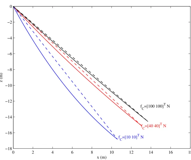
2.4 Proiles of the example cable under different external forces: the solid lines and the dashed lines represent the cable proiles and the cable chords,
respectively . . . 31
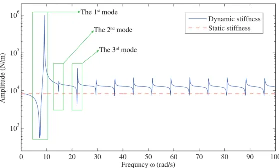
2.5 Amplitude variation of the trace of the dynamic and static stiffness matrix
for the example cable . . . 33
3.1 The schematic diagram of a suspended CDPR . . . 37
3.2 Deinition of the static pose error . . . 41
3.3 The schematic diagram of the studied CDPR (6-DOF suspended by 8 cables) 49
3.4 Static pose error of the end-effector along axis-zG over a sub-workspace
(−3 m 6 xG63 m, −3 m 6 yG63 m, zG= 0.5 m) for φ 4 mm cable and
3.5 Static pose error of the end-effector along axis-zG over a sub-workspace
(−3 m 6 xG63 m, −3 m 6 yG63 m, zG= 0.5 m) for φ 4 mm cable and
60 kg external load . . . 50
3.6 Static pose error of the end-effector along axis-zG over a sub-workspace
(−3 m 6 xG63 m, −3 m 6 yG63 m, zG= 0.5 m) for φ 8 mm cable and
30 kg external load . . . 51
3.7 Static pose error of the end-effector along axis-zG over a sub-workspace
(−3 m 6 xG63 m, −3 m 6 yG63 m, zG= 0.5 m) for φ 8 mm cable and
60 kg external load . . . 51
3.8 Vibration analysis of the studied CDPR when the end-effector is at the center
of the sub-workspace (xG= 0 m, yG= 0 m and zG= 0.5 m) . . . 53
3.9 The irst natural frequency of the studied CDPR over a sub-workspace
(−3 m 6 xG63 m, −3 m 6 yG63 m, zG= 0.5 m) . . . 55
4.1 The CDPR prototype with 6 cables . . . 59
4.2 The schematic diagram of the CoGiRo [Lamaury+ 2013] . . . 60
4.3 Static experimental setup . . . 61
4.4 Effect of external load on the static pose error of the 6-cable CDPR prototype. 62
4.5 Measurement of the static cable forces of the CoGiRo . . . 65
4.6 Modal analysis of the CoGiRo by the shaker . . . 67
4.7 Experimental and simulation results of the vibration analysis of the 5th cable
at the pose near the center of the workspace (x = 0.012 m; y = 0.0697 m;
z= 1.219 m; α, β , γ = 0°) . . . 69
4.8 Experimental and simulation results of the vibration analysis of the 5th cable
at the pose near the edge of the workspace (x = 4.012 m; y = 0.0697 m;
z= 1.219 m; α, β , γ = 0°) . . . 70
4.9 Experimental and simulation results of the vibration analysis of the end-effector at the pose near the center of the workspace (x = 0.012 m; y = 0.0697
m; z = 1.219 m; α,β ,γ = 0°) . . . 71
4.10 Experimental and simulation results of the vibration analysis of the end-effector at the pose near the edge of the workspace (x = 4.012 m; y = 0.0697
m; z = 1.219 m; α,β ,γ = 0°) . . . 72
4.11 Free vibration experiment at an emergency stop . . . 76
4.12 Experimental results of the free vibration analysis of the 5thcable during a
List of Figures xxvii 4.13 Experimental results of the free vibration analysis of the end-effector along
axis-x during a trajectory containing an emergency stop . . . 78
4.14 Experimental results of the free vibration analysis of the end-effector along
axis-z during a trajectory containing an emergency stop . . . 79
4.15 Experimental setup of the analysis along a trajectory . . . 80
4.16 Pose error of the end-effector during the trajectory from x = 1 m; y = −2 m;
z= 0 m; α, β , γ = 0°to x = −0.5 m; y = −0.7 m; z = −0.25 m; α, β , γ =
0°with different trajectory time durations . . . 81
4.17 Experimental results of the vibration analysis of the end-effector along axis-z
during the trajectory of 30 seconds . . . 82
5.1 Kinematic model of a general CDPR considering cable sag . . . 88
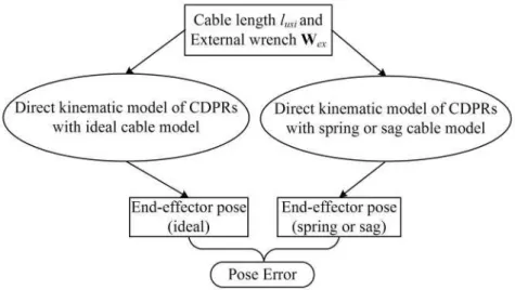
5.2 Flow chart of the force distribution of CDPRs . . . 93
5.3 Coniguration of the 6 DOF CDPR driven by 8 cables . . . 95
5.4 The variation of the lower-boundary along the trajectory: the blue solid lines represent the results of the ixed lower-boundary; the red dash lines represent
the results of the pose-dependent lower-boundary . . . 97
5.5 The variation of the cable force along the trajectory: the blue solid lines represent the results of the ixed lower-boundary; the red dash lines represent
the results of the pose-dependent lower-boundary . . . 98
5.6 The energy consumption of the CDPR along the trajectory: the blue solid lines represent the results of the ixed lower-boundary; the red dash lines
represent the results of the pose-dependent lower-boundary . . . 99
A.1 The electrodynamic vibration shaker . . . 119 A.2 The Nikon K-600 camera system . . . 120 A.3 Sensors in the experiments . . . 120 A.4 The data acquisition system . . . 121
List of Tables
2.1 Physical parameters of the studied cable . . . 30
2.2 Static cable parameters of the example cable under different external forces 30
2.3 Static compliance and stiffness matrix of the example cable under different
external forces . . . 31
2.4 Dynamic cable parameters of the example cable under different external forces 32
3.1 Coniguration parameters of the studied CDPR: coordinates ofBiexpressed
in global frame ℜG; coordinates of Aiexpressed in end-effector frame ℜe . 49
3.2 Average values of the pose errors in the sub-workspace (−3 m 6 xG63 m,
−3 m 6 yG63 m, zG= 0.5 m) . . . 50
4.1 Coniguration parameters of the 6-cable CDPR prototype: coordinates of the
points Biin the global frame ℜGand that of Aiin the local frame ℜe . . . . 59
4.2 Cable parameters of the 6-cable CDPR prototype . . . 59
4.3 Coniguration parameters of the CoGiRo: coordinates of Bi expressed in
global frame ℜG; coordinates of Aiexpressed in end-effector frame ℜe . . . 61
4.4 Static forces of the driving cables measured at different poses of the
end-effector in the workspace . . . 66
4.5 Cable natural frequencies identiied by experiments and simulations at the pose near the center of the workspace (x = 0.012 m; y = 0.0697 m; z = 1.219
m; α,β ,γ = 0°) . . . 68
4.6 Cable natural frequencies identiied by experiments and simulations at the pose near the edge of the workspace (x = 4.012 m; y = 0.0697 m; z = 1.219
m; α,β ,γ = 0°) . . . 68
5.1 Parameters of the end-effector and the driving cables . . . 95
5.2 Coordinates of the attachments Bi in the global frame and Ai in the local
Nomenclature
AbbreviationCDPR Cable-Driven Parallel Robot, page 1
DSM Dynamic Stiffness Matrix, page 14
FEM Finite Element Method, page 14
FRF Frequency Response Function, page 64
Coordinate system
ℜe Local frame ixed on the end-effector, page 37
ℜG Global frame of CDPRs, page 37
ℜBi Auxiliary frame, page 37
ℜci Local cable frame, page 37
Matrix eK
E(ω) Dynamic stiffness matrix of CDPRs expressed in the end-effector frame ℜe,
page 44 GK
E(ω) Dynamic stiffness matrix of CDPRs expressed in the global frame ℜG,
page 44 GK
i(ω) Dynamic stiffness matrix of the ithinclined sagging cable expressed in the
global frame ℜG, page 44
GT
e Rotation matrix transferring the coordinates in ℜe to their corresponding
GT
ci Rotation matrix that transfers the coordinates in ℜcito their corresponding
coordinates in ℜG, page 38
ciK
i(ω) Dynamic stiffness matrix of the ithinclined sagging cable expressed in the
cable frame ℜci, page 44
C2Daxial Compliance matrix caused by the axial cable elasticity, page 24
C2Dsag Compliance matrix caused by the sag-introduced lexibility, page 24
C2Dstatic Static compliance matrix of an inclined sagging cable (2 by 2 matrix), page 23
JT Transposition of the Jacobian matrix, page 39
K3Ddyn-h(ω) Dynamic stiffness matrix of a horizontal sagging cable in 3-D, page 27
K2Dstatic Static stiffness matrix of an inclined sagging cable (2 by 2 matrix), page 23
H(ω) Frequency Response Function matrix, page 47
K2Ddyn-h(ω) Dynamic stiffness matrix of a horizontal sagging cable in the cable plan (2-D), page 26
K2Ddyn(ω) Dynamic stiffness matrix of an inclined sagging cable in the cable plan,
page 28
K3Ddyn(ω) Dynamic stiffness matrix of an inclined sagging cable in 3-D, page 29
eM 6 by 6 mass matrix of the end-effector expressed in frame ℜ
e, page 45
Scalar
α Inclined angle of the cable, page 21
∆l Cable elongation, page 23
˙qi Time derivatives of the generalized coordinate, page 45
λ2 Fundamental cable parameter representing the elastic stiffness relative to the
catenary stiffness, page 27
Nomenclature xxxiii
τ Static cable tension at the section where the cable is parallel to the chord,
page 21
ε Ratio between horizontal cable weight and cable tension, page 27
A Unstrained cross-sectional area of the cable, page 21
d Cable sag perpendicular to the chord, page 21
E Young's modulus, page 21
Fi Nonconservative generalized force or moment applied to the end-effector,
page 45
lc Chord length of the cable, page 21
Le Cable length parameter, page 27
ls Strained cable length between points C and B, page 21
lus Unstrained cable length between points C and B, page 21
m Number of driving cables, page 39
n Number of DOFs of the end-effector, page 39
qi Generalized coordinate, page 45
s Lagrangian coordinate in the unstrained cable proile, page 21
T Kinetic energy of the system, page 45
V Potential energy of the system, page 45
Ωc Dimensionless frequency±damping parameter, page 27
Ω Dimensionless frequency parameter, page 27
Vector
¯f Column complex-valued vector representing the amplitudes and the initial
phases of the excitations, page 47
¯q Column complex-valued vector representing the amplitudes and the initial
˙q Column vectors of the time derivatives of the generalized coordinates, page 45
Gf
Ai Cable force vector at point Aiexpressed in global frame ℜG, page 39
Gf
ex External force vector expressed in global frame ℜG, page 39
Gm
ex External moment vector expressed in global frame ℜG, page 39
cif
Ai Cable force vector at point Aiexpressed in global frame ℜci, page 39
f(t) Column vector of the harmonic excitations applied to the end-effector,
page 47
q(t) Column vector of the harmonic responses of the end-effector, page 47
fideal Column vector of the ideal cable forces, page 40
q Column vectors of the generalized coordinates, page 45
Chapter 1
Introduction
Contents
1.1 Presentation of CDPRs . . . 1 1.2 Problematic and current researches . . . 9 1.3 Objectives of this thesis . . . 13
1.1
Presentation of CDPRs
A generalized parallel robot can be deined as a closed-loop kinematic chain mechanism whose end-effector is linked to the base by several independent kinematic chains [Merlet 2006].
Traditional parallel robots use rigid links to form the kinematic chains, such as the famous Gough-Stewart platform (ig. 1.1a) [Gough 1957; Stewart 1965] and the well known Delta robot (ig. 1.1b) [Clavel 1991]. Rigid-link parallel robots are used in various applications, such as tire test machines (ig. 1.1a) [Gough 1957], light simulators (ig. 1.2a) [Koever-mans+ 1975], surgery operations (ig. 1.2b) [Briot+ 2007], space antennas [Dunlop+ 1999], machine tools [Weck+ 2002], etc. Compared to their serial counterparts, rigid-link parallel robots have advantages such as large load carrying capacity, high stiffness, low inertia, etc. However, their main inconvenience is the relatively small workspace.
Cable-driven parallel robots (CDPRs) are a special variant of traditional rigid-link parallel robots. They use lexible cables instead of rigid links to connect the movable end-effector and the ixed base. The end-effector is manipulated by changing the length of the cables that are actuated by ixed motors and winches. As a kind of parallel robots, CDPRs also have
advantages in load capacity, stiffness, energy eficiency and so on. Furthermore, CDPRs overcome the major weakness of rigid-link parallel robots: workspace. Unlike rigid links, cable lengths can vary in a wide range, which enlarges the workspace of CDPRs. These characteristics have attracted a lot of interest of researchers in the past few decades.
(a) The original Gough-Stewart platform [Gough 1957]
(b) The irst Delta robot [Clavel 1991] Fig. 1.1 Two famous rigid-link parallel robots
(a) The Airbus A320 simulator1 (b) The Surgiscope2
Fig. 1.2 Two examples of applications of the rigid-link parallel robots
1The Airbus A320 simulator is a product of Baltic Aviation Academy: http://www.balticaa.com 2The Surgiscope is a product of ISIS corporation: http://www.isis-robotics.com/
1.1 Presentation of CDPRs 3
1.1.1
Advantages and applications of CDPRs
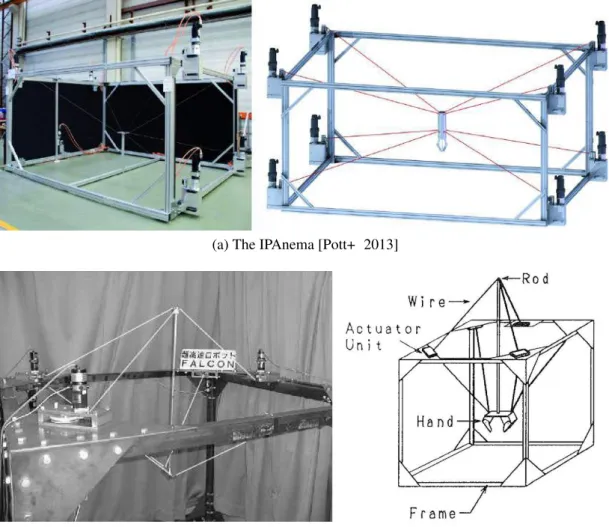
(a) The IPAnema [Pott+ 2013]
(b) The FALCON [Kawamura+ 1995]
Fig. 1.3 Examples of CDPRs with high dynamics
Large workspace
Firstly of all, CDPRs can achieve large workspaces. As cables are lexible, they can be easily released and retracted through winches. Thus, cables allow a much larger range of motion compared to conventional rigid links. For example, the workspace of the prototype REELAX8-S [Lamaury 2013], a 6-DOF CDPR suspended by 8 cables, can reach up to 78% of the volume of the robot. By contrast, the workspace of a rigid-link parallel robot PAR4 [Lamaury 2013; Nabat 2007] represents only 31% of the volume of the robot.
High dynamics
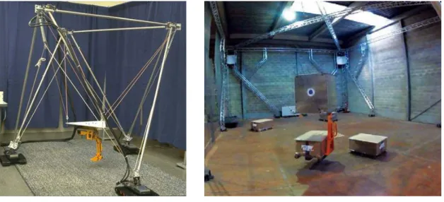
Furthermore, CDPRs have high dynamics. Because cables are lighter than most of the conventional rigid links and they have small mobile mass and low inertia, CDPRs are suitable for high velocity and/or high acceleration applications, such as the IPAnema (ig. 1.3a) [Pott+ 2010; Pott+ 2013] and the FALCON (ig. 1.3b) [Kawamura+ 1995; Kawamura+ 2000]. For example the FALCON robot can attain a peak speed of about 13 m/s, and a peak acceleration of 43 G [Kawamura+ 1995].
(a) The ROBOCRANE [Albus+ 1993] (b) The CoGiRo [Lamaury 2013] Fig. 1.4 Examples of CDPRs with large load capacity
Large payload capacity and high energy eficiency
In addition, CDPRs have large payload capacity and high energy eficiency. For serial robots, the energy consumption is high and the payload capacity is low, because each actuator has to carry not only the payload in the end-effector, but also the weight of all the subsequent links and actuators. Traditional rigid-link parallel robots are more eficient compared to serial robots, because their actuators are usually ixed and the payload can be shared by each link. But the movement of the rigid links still consume lots of useless energy. CDPRs use lightweight cables instead of relatively heavy rigid links. They usually have stationary heavy components and few moving parts. The energy consumption is focused on the movement of the end-effector and payload is shared by many driving cables, resulting very high energy eficiency and high payload-to-weight ratios, such as the ROBOCRANE (ig. 1.4a) [Albus+ 1992; Albus+ 1993; Bostelman+ 1994] and the CoGiRo (ig. 1.4b) [Lamaury+ 2013]. For
1.1 Presentation of CDPRs 5 example the load capacity of the CoGiRo prototype [Lamaury 2013] can reach 500 kg, while the total mass of the moving parts of the robot including the end-effector and the driving cables is only about 100 kg.
(a) The Skycam3 (b) The FAST [Nan 2006]
Fig. 1.5 Examples of CDPRs with extremely large scale
Low cost
Besides the above advantages, CDPRs have low cost. As the price of electronic components are becoming lower, while the price of mechanical parts keeps quite stable, there is a trend to design robots with simple mechanical structures but relatively complex electronic devices. CDPRs it this trend and thus they can be designed in extremely large scale within an
acceptable cost, such as the Skycam 3 (ig. 1.5a), and the Five hundred meter Aperture
Spherical Telescope (FAST, ig. 1.5b) [Zi+ 2008; Nan 2006]. Simple structure
Another advantage of CDPRs is their simple structure. They can be easily disassembled, reassembled, transported and reconigured. The position of the attachment points can be modiied and determined by a calibration of the system [Sandretto+ 2013a; Borgstrom+ 2009; Miermeister+ 2012]. This characteristic makes CDPRs suitable for search and rescue applications (ig. 1.6) [Tadokoro+ 1999; Bosscher+ 2005; Merlet+ 2010; Merlet 2010].
Fig. 1.6 The MARIONET-CRANE for emergency rescue by [Merlet 2010]
Good safety
Last but not least, CDPRs have a good safety during operations. As cables are lexible, they provide a natural protection during interference with each other or with other objects in the environment [Mao+ 2012; Rosati+ 2005]. This characteristic makes CDPRs quite useful for haptic devices, such as the NEREBOT (ig. 1.7a) [Gallina+ 2002] and the STING-MAN (ig. 1.7b) [Surdilovic+ 2007].
(a) The NEREBOT [Gallina+ 2002] (b) The STING-MAN [Surdilovic+ 2007] Fig. 1.7 Examples of CDPRs for haptic applications
1.1 Presentation of CDPRs 7
1.1.2
Classiication of CDPRs
Suspended and non-suspended CDPRs
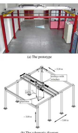
According to the arrangement of cables, two kinds of CDPRs can be considered. One kind is suspended CDPRs, where all the driving cables are above the end-effector and gravity acts as a virtual cable to keep equilibrium, such as the CableV (ig. 1.8) [Heyden+ 2006], the ROBOCRANE (ig. 1.4a) [Albus+ 1993], the CoGiRo (ig. 1.4b) [Lamaury 2013], the Skycam (ig. 1.5a), the FAST (ig. 1.5b) [Nan 2006], etc. The other kind is non-suspended CDPRs, where at least one driven cable is below the end-effector, such as the FALCON (ig. 1.3b) [Kawamura+ 1995], the IPAnema (ig. 1.3a) [Pott+ 2013], the SEGESTA (ig. 1.9) [Hiller+ 2005; Fang+ 2004], etc. It should be noticed that CDPRs working on a horizontal plane are classiied as non-suspended CDPRs. Because the weight of the end-effector is balanced by the support of the plane, gravity has no effect on the equilibrium of the end-effector.
For suspended CDPRs, since all the cables are above the end-effector, the payload can be shared by each cable, thus suspended CDPRs usually have big load capacity. Moreover, compared with non-suspended CDPRs, there is less possibility for the cables to interfere with other objects in the environment because no cable is lower than the end-effector. These two characteristics make suspended CDPRs quite suitable for pick-and-place applications, just like cranes. However, suspended CDPRs may become unstable, easy to vibrate and even out of control under external disturbances, especially when the end-effector is unloaded. This weakness is due to the low stiffness of CDPRs along the vertical direction. Therefore, it is necessary to pay more attention to the stiffness analysis of suspended CDPRs in order to improve their accuracy and reduce their vibration.
For non-suspended CDPRs, stiffness and positioning accuracy can be improved and vibration can be reduced through increasing the internal cable forces. Consequently, non-suspended CDPRs usually have better performances in high velocity and/or acceleration applications compared to suspended CDPRs. However, the motor power and energy con-sumption will signiicantly increase with growing internal cable forces, which can augment the fabrication and the operation costs.
Redundant actuated and non-redundant actuated CDPRs
According to the relationship between the number of driving cables (m) and the number of degree of freedom of the end-effector (n), two kinds of CDPRs can be discussed. One kind is redundant actuated CDPRs, where m > n, such as the FALCON (m=7, n=6, ig. 1.3b)
(a) The prototype
(b) The schematic diagram
Fig. 1.8 Example of a suspended and non-redundant actuated CDPR: the CableV [Heyden+ 2006]
[Kawamura+ 1995], the CoGiRo (m=8, n=6, ig. 1.4b) [Lamaury 2013], the IPAnema (m=8, n=6, ig. 1.3a) [Pott+ 2013], the SEGESTA (m=8 or 7, n=6, ig. 1.9) [Hiller+ 2005], and the Skycam (m=4, n=3, ig. 1.5a). The other kind is non-redundant actuated CDPRs, where
m≤ n, such as the CableV (m=3, n=3, ig. 1.8) [Heyden+ 2006], the ROBOCRANE (m=6,
n=6, ig. 1.4a) [Albus+ 1993], and the FAST (m=6, n=6, ig. 1.5b) [Nan 2006].
Compared to non-redundant actuated CDPRs, redundant actuated CDPRs have some advantages. Through adding redundant driving cables, workspace can be extended, singularity can be reduced and stiffness can be increased. In addition, payload are redistributed to more cables and the tension of the driving cable can be decreased, which can decrease the motor size. Moreover, safety can be enhanced by using redundant cables. The end-effector maybe still controllable even if some of the redundant cables are out of control. Another
1.2 Problematic and current researches 9
(a) The prototype (b) The schematic diagram (8 or 7 cables)
(c) Its application in wind tunnels
Fig. 1.9 Example of a non-suspended and redundant actuated CDPR: the SEGESTA [Hiller+ 2005; Bruckmann+ 2010]
inconvenience of redundant actuated CDPRs is the increasing risk of cable collision. Anti-collision should be paid more attention in the design and trajectory planing [Lahouar+ 2009; Nguyen+ 2015].
1.2
Problematic and current researches
1.2.1
Cable force analysis
One major characteristic of cables is that they can only act in tension. If some cables loose tension, CDPRs may become unstable and even out of control. Therefore, it is an important issue to keep all the driving cables in tension during the movement of CDPRs. This positive-cable-force requirement brings some challenges to CDPRs.
In order to guarantee the positive cable forces, lots of works are presented in literature aiming to ind optimal and positive distributions of cable forces, especially for high redundant actuated CDPRs [Gosselin+ 2011; Mikelsons+ 2008; Pott+ 2009; Khosravi+ 2013]. A related problem is the controller design of CDPRs, which must take the positive-cable-force requirement into account. A number of researches have investigated the controller design of CDPRs [Oh+ 2005; Fang+ 2004; Vafaei+ 2011; Zi+ 2008; Dallej+ 2012; Lamaury+ 2013]. The force distribution problem of CDPRs will be further addressed in Chapter 5.
Another issue is the determination of the workspace. The workspace of CDPRs is not only related to the geometric constrain of CDPRs, but also limited by the cable tensions. Considering the positive-cable-force requirement and the static and/or dynamic performances of CDPRs, different kinds of workspace can be deined, such as the Static Equilibrium Workspace [Pusey+ 2004], the Dynamic Workspace [Barrette+ 2005], the Wrench-Feasible Workspace [Bosscher+ 2006; Gouttefarde+ 2007], etc.
1.2.2
Stiffness analysis
Due to the compliance of cables, the stiffness of robots becomes a vital concern [Gouttefarde+ 2012; Riehl+ 2009], especially for suspended CDPRs. Stiffness has a signiicant effect on the static and dynamic behaviors of CDPRs, such as kinematics, positioning accuracy, force distribution, vibration and control [Gosselin 1990; Merlet 2006]. Deicient static stiffness can decrease the positioning accuracy of CDPRs, and bad dynamic stiffness characteristics can lead to vibration and long settling time. Although stiffness has been well studied in the last few decades for rigid-link parallel robots [Gosselin 1990; Carbone 2011; Courteille+ 2009; Merlet 2006; Deblaise+ 2006; ElKhasawneh+ 1999], there is little literature on the stiffness problem of CDPRs. This thesis will focus on the static and dynamic stiffness analyses of CDPRs.
Static stiffness
An important issue closely associated with the static stiffness is the positioning accuracy of CDPRs. For example, this issue is especially important for suspended pick-and-place CDPRs, such as the CoGiRo [Nguyen+ 2013]. The reasons are as following. On one hand, cables should be designed strong enough to sustain the weight of heavy cargo. A common way to enhance the load capacity of cables is to increase their diameter, which directly leads signiicant growth of cable weight. One the other hand, the end-effector should be designed as light as possible to improve the eficiency of pick-and-place. When the end-effector is
1.2 Problematic and current researches 11 unloaded, the cable sag will become quite signiicant. In this situation, the ideal cable model and the spring cable model that neglect the effect of cable weight on the static cable proile can bring big error in the prediction of the pose of the end-effector. For a traditional rigid-link manipulator, the pose error can be deined by its Cartesian stiffness matrix, assuming the compliant displacements of the end-effector are small [Carbone 2011]. However, due to the nonlinearity of sagging cable, the small displacement assumption is not valid. For example, the static compliant displacement of the CoGiRo (15×11×6 m, l × w × h) can even research 13.9 cm with 210 kg external load according to [Nguyen+ 2013]. In this situation, other methods should be found to compute the pose error.
The compliance of driving cables is the major factor that affects the positioning accuracy of CDPRs. Considering the physical cable characteristics, the compliance of cables mainly has two sources. One is the axial stiffness of the cables, which is associated with the elastic modulus of the material of cables. The other is the sag-introduced lexibility, which corresponds to the gravitational potential energy stored in the cable. Therefore, for the stiffness and accuracy analysis of CDPRs, an important issue is cable modeling. Many studies used linear or non-linear spring as cable model [Verhoeven+ 1998; Dagalakis+ 1989; Kawamura+ 1995; Kawamura+ 2000; Behzadipour+ 2006; Korayem+ 2007; Bedoustani+ 2008; Vafaei+ 2011; Khosravi+ 2013]. This approach only considers the elasticity along cable axis and assumes cable as massless spring. This assumption is not accurate enough, especially for CDPRs with heavy and/or long-span cables. In fact, the static cable proile under the effect of gravity is not a straight line but a sagging curve. Thus the axial cable elasticity is not the only source of the static stiffness of CDPRs, since sag-introduced lexibility should also be considered. A well known model considering the sag-introduced stiffness is the static sagging cable model deriving from civil engineering [Irvine 1992]. It is used in several previous researches [Kozak+ 2006; Riehl+ 2009; Gouttefarde+ 2012; Sandretto+ 2013b; Arsenault 2013]. The sagging cable model considers the cable elasticity and the effect of cable weight on the static cable proile. It is more accurate than the spring cable model in the static stiffness analysis of CDPRs. In previous researches [Kozak+ 2006; Riehl+ 2009; Arsenault 2013], the effect of cable sag on the static stiffness of CDPRs is only veriied by numerical simulations. Experimental veriication of the static stiffness is performed on single cables, but not on CDPRs in [Kozak+ 2006; Irvine 1992]. To our best knowledge, the only experimental validation of the sagging cable model on a complete CDPR is presented in [Nguyen+ 2013].
Since the stiffness performances of robots are important for the design and control of CDPRs, another considerable issue is the index of stiffness performance evaluation.
Most studies [Arsenault 2013; Verhoeven+ 1998; Dagalakis+ 1989] use Cartesian stiffness matrix or its mathematical properties (such as determinant, trace, norm, and etc) as evaluation indexes. For massless cable assumption, the static stiffness of CDPRs only depends on the axial stiffness of cables. In linear-elastic range of the cable, the axial stiffness is independent of cable forces. Thus the Cartesian stiffness matrix of the robot is independent of the external wrench applied to the end-effector. It is easy to compute the Cartesian stiffness matrix through the Jacobian matrix of CDPRs. However, considering the effect of cable weight, the cable proile between two attachment points is not a straight line but a sagging curve. So the direction of cable force is not along the chord of the curve but tangential to the sagging curve. In this case, Jacobian matrix cannot be used to calculate the Cartesian stiffness matrix, and partial differential equations should be employed instead [Arsenault 2013]. This increases calculation complexity. Furthermore, taking the cable sag into consideration, the stiffness of cables is relevant to cable forces and thus depends on the external payload.
Dynamic stiffness
Although there are lots of researches on the vibration analysis and control for rigid-link parallel robots [Kozak+ 2004; Piras+ 2005; Yun+ 2010; Wang+ 2006; Gexue+ 2004; Algermissen+ 2005; Hesselbach+ 2004; Kang+ 2005; Zhang+ 2008; Mitsuta+ 1994], only few studies can be found on the vibration analysis of CDPRs [Diao+ 2009; Ma+ 2005; Tang+ 2013; Weber+ 2014; Kozak+ 2006; Du+ 2012; Du+ 2013; Kozak+ 2006]. Because CDPRs are quite new in the big family of robotics, most researches remain on the design, simulation and prototype manufacturing. Recently more and more CDPRs are designed and built aiming to be used in real applications. Some of them require high performances, especially the dynamic performances. For examples: the ultrahigh speed FALCON robot [Kawamura+ 1995; Kawamura+ 2000], the wind-induced vibration problem of the large radio telescope [Zi+ 2008] and the wind tunnels (ig. 1.9c) [Bruckmann+ 2010]. Vibration can be induced by initial position and velocity of the end-effector, wind disturbance, and/or friction of the cables around ixed pulleys [Du+ 2012]. Vibration can affect the positioning accuracy of the end-effector, and bring luctuation on the trajectory. These applications lead to researches on the dynamic stiffness and vibration problem of CDPRs.
The vibration of CDPRs can be affected by the compliance of the driving cables, the actuators and the end-effector. Compared with cables, the compliance of the actuators and the end-effector is much lower and therefore can be neglected. Thus the compliance of cables is the primary reason for the vibration of CDPRs. Cable vibration, the rigid-body modes of the end-effector suspended on the stiffness of the cables and their coupling should be
1.3 Objectives of this thesis 13 considered in the dynamic analysis of CDPRs.
Cables have been modeled as taught strings, and end-effector vibration caused by axial and transversal cable lexibility has been analyzed by simulations in [Diao+ 2009; Ma+ 2005]. Cables are modeled as linear massless axial springs, and vibration characteristics of a CDPR for processing applications are presented in [Tang+ 2013]. Vibrations are analyzed based on the linear spring cable model, and a new approach using reaction wheels to compensate the rotational oscillations of the end-effector is proposed in [Weber+ 2014]. Finite element method has been used in the modeling of cable dynamics, and the end-effector vibration together with the system natural frequencies have been studied by simulations in [Du+ 2013; Du+ 2012]. Robot stiffness matrix has been deduced and system natural frequencies have been calculated in [Kozak+ 2006].
Most of these researches [Diao+ 2009; Ma+ 2005; Tang+ 2013; Weber+ 2014] only consider cable elasticity, while neglecting the effect of cable mass on the cable dynamics. Although the effect of cable weight on the static cable proile is considered for the static analysis in [Kozak+ 2006], the effect of cable mass on the cable dynamics is totally ignored in the computation of robot natural frequencies. The effect of cable mass on the cable dynamics is taken into account in the inite element cable model in [Du+ 2012; Du+ 2013]. However, this cable model is based on the Finite Element Method (FEM), and it uses distributed mass points and ideal lines between them to simulate continuous cable. Thus it leads to a very complex system with many partial differential equations. Moreover, as it is known, the accuracy of inite element method depends on the number of elements. To ensure a good accuracy will result in further computational complexity.
To sum up, some researches consider the effect of cable mass on the cable dynamics, while most researches neglect this effect. Thus, whether the effect of cable mass on the cable dynamics is signiicant for the robot dynamics or not still remains unknown in the existing literatures. Moreover, how to set up an complete dynamic cable model that considers the cable dynamics, the end-effector vibrations and their coupling is still a challenge. In addition, experimental validation should be also considered.
1.3
Objectives of this thesis
The main objective of this thesis is to analyze the static and dynamic stiffness of CDPRs with considering the effect of cable sagging and cable dynamic, aiming to improve their static positioning accuracy and trajectory tracking for high dynamic applications. To achieve this objective, the following sub-objectives are made.
![Fig. 1.6 The MARIONET-CRANE for emergency rescue by [Merlet 2010]](https://thumb-eu.123doks.com/thumbv2/123doknet/14500885.719196/41.892.225.650.161.431/fig-marionet-crane-emergency-rescue-merlet.webp)

![Table 2.2 Static cable parameters of the example cable under different external forces External forces [ f Cx f Cz ] T (N) [10 10] T [40 40] T [100 100] T End-point coordinate (x C z C ) (m) (10.59 -16.83) (13.06 -15.13) (13.70 -14.58) Inclined angle α (°)](https://thumb-eu.123doks.com/thumbv2/123doknet/14500885.719196/65.892.128.747.568.712/static-parameters-example-different-external-external-coordinate-inclined.webp)