HAL Id: tel-02067934
https://tel.archives-ouvertes.fr/tel-02067934
Submitted on 14 Mar 2019
HAL is a multi-disciplinary open access archive for the deposit and dissemination of sci-entific research documents, whether they are pub-lished or not. The documents may come from teaching and research institutions in France or abroad, or from public or private research centers.
L’archive ouverte pluridisciplinaire HAL, est destinée au dépôt et à la diffusion de documents scientifiques de niveau recherche, publiés ou non, émanant des établissements d’enseignement et de recherche français ou étrangers, des laboratoires publics ou privés.
Single-pixel imaging : Development and applications of
adaptive methods
Florian Rousset
To cite this version:
Florian Rousset. Single-pixel imaging : Development and applications of adaptive methods. Signal and Image processing. Université de Lyon; Politecnico di Milano, 2017. English. �NNT : 2017LYSEI096�. �tel-02067934�
N° d’ordre NNT : 2017LYSEI096
THESE de DOCTORAT DE L’UNIVERSITE DE LYON
opérée au sein de
l’Institut National des Sciences Appliquées de Lyon
et délivrée en cotutelle internationale avec
le Politecnico di Milano
Ecole Doctorale
N°160
Electronique, Electrotechnique, Automatique
Spécialité de doctorat
:Traitement du Signal et de l’Image
Soutenue publiquement le 27/10/2017 par :
Florian R
OUSSET
S
INGLE
-P
IXEL
I
MAGING
:
DEVELOPMENT AND APPLICATIONS
OF ADAPTIVE METHODS
Devant le jury composé de :
BARANIUK Richard PR University of Rice Rapporteur
SOUSSEN Charles PR CentraleSupélec Rapporteur
ARRIDGE Simon PR University College London Examinateur
TARONI Paola PR Politecnico di Milano Examinateur
PEYRIN Françoise DR INSERM Directrice de thèse
D’ANDREA Cosimo MCF Politecnico di Milano Co-directeur de thèse
Département FEDORA – INSA Lyon - Ecoles Doctorales – Quinquennal 2016-2020
SIGLE ECOLE DOCTORALE NOM ET COORDONNEES DU RESPONSABLE
CHIMIE
CHIMIE DE LYON
http://www.edchimie-lyon.fr
Sec : Renée EL MELHEM Bat Blaise Pascal 3e etage [email protected] Insa : R. GOURDON
M. Stéphane DANIELE
Institut de Recherches sur la Catalyse et l'Environnement de Lyon IRCELYON-UMR 5256
Équipe CDFA
2 avenue Albert Einstein 69626 Villeurbanne cedex [email protected] E.E.A. ELECTRONIQUE, ELECTROTECHNIQUE, AUTOMATIQUE http://edeea.ec-lyon.fr Sec : M.C. HAVGOUDOUKIAN [email protected] M. Gérard SCORLETTI
Ecole Centrale de Lyon 36 avenue Guy de Collongue 69134 ECULLY Tél : 04.72.18 60.97 Fax : 04 78 43 37 17 [email protected] E2M2 EVOLUTION, ECOSYSTEME, MICROBIOLOGIE, MODELISATION http://e2m2.universite-lyon.fr
Sec : Sylvie ROBERJOT Bât Atrium - UCB Lyon 1 04.72.44.83.62
Insa : H. CHARLES
M. Fabrice CORDEY
CNRS UMR 5276 Lab. de géologie de Lyon Université Claude Bernard Lyon 1 Bât Géode
2 rue Raphaël Dubois 69622 VILLEURBANNE Cédex Tél : 06.07.53.89.13 cordey@ univ-lyon1.fr EDISS INTERDISCIPLINAIRE SCIENCES- SANTE http://www.ediss-lyon.fr
Sec : Sylvie ROBERJOT Bât Atrium - UCB Lyon 1 04.72.44.83.62
Insa : M. LAGARDE
Mme Emmanuelle CANET-SOULAS
INSERM U1060, CarMeN lab, Univ. Lyon 1 Bâtiment IMBL
11 avenue Jean Capelle INSA de Lyon 696621 Villeurbanne Tél : 04.72.68.49.09 Fax :04 72 68 49 16 [email protected] INFOMATHS INFORMATIQUE ET MATHEMATIQUES http://infomaths.univ-lyon1.fr
Sec :Renée EL MELHEM Bat Blaise Pascal, 3e étage Tél : 04.72. 43. 80. 46 Fax : 04.72.43.16.87 [email protected] M. Luca ZAMBONI Bâtiment Braconnier 43 Boulevard du 11 novembre 1918 69622 VILLEURBANNE Cedex Tél :04 26 23 45 52 [email protected] Matériaux MATERIAUX DE LYON http://ed34.universite-lyon.fr
Sec : Marion COMBE
Tél:04-72-43-71-70 –Fax : 87.12 Bat. Direction [email protected] M. Jean-Yves BUFFIERE INSA de Lyon MATEIS
Bâtiment Saint Exupéry 7 avenue Jean Capelle 69621 VILLEURBANNE Cedex
Tél : 04.72.43 71.70 Fax 04 72 43 85 28 [email protected]
MEGA
MECANIQUE, ENERGETIQUE, GENIE CIVIL, ACOUSTIQUE
http://mega.universite-lyon.fr
Sec : Marion COMBE
Tél:04-72-43-71-70 –Fax : 87.12 Bat. Direction [email protected] M. Philippe BOISSE INSA de Lyon Laboratoire LAMCOS Bâtiment Jacquard 25 bis avenue Jean Capelle 69621 VILLEURBANNE Cedex Tél : 04.72 .43.71.70 Fax : 04 72 43 72 37 [email protected] ScSo ScSo* http://recherche.univ-lyon2.fr/scso/
Sec : Viviane POLSINELLI Brigitte DUBOIS Insa : J.Y. TOUSSAINT Tél :04 78 69 72 76 [email protected] M. Christian MONTES Université Lyon 2 86 rue Pasteur 69365 LYON Cedex 07 [email protected]
A
CKNOWLEDGMENTS
I would first like to express my deepest appreciation to my three Supervisors, Françoise Peyrin, Nicolas Ducros, and Cosimo D’Andrea.
I thank Françoise for accepting to act as my PhD Director. This gave me the opportunity to benefit from her broad experience, and her reviews and advice during my research work. Although setting up the videoconferencing was quite tricky, our meetings were always very constructive and fruitful, which undoubtedly contributed to the success of my Project.
I express my special thanks to Nicolas, who was by my side at CREATIS and has always been here to answer my questions. His knowledge in optics, and image processing in general, has been a great help throughout these 3 years. His scientific rigor, enthusiasm, and passion were a source of motivation and will surely bring success to his accepted project in single-pixel imaging. I also thank him for giving me the opportunity to do some teaching hours at INSA.
I wish to thank Cosimo, without whom I could not have performed any of the experimental ac-quisition presented in this thesis. My somewhat basic knowledge in optics was definitely not enough to understand everything, but Cosimo always made things clear with simple, yet efficient, explana-tions. I am also grateful for the help Cosimo provided upon my arrival in Milan, regarding paperwork and housing.
I would like to express my gratitude to Isabelle Magnin, for welcoming me to the CREATIS la-boratory, which she managed until 2015, to Olivier Beuf, who followed as CREATIS Director, and to Franco Ciccacci, Head of the Dipartimento di Fisica at the Politecnico di Milano. They all gave me the opportunity to conduct my work in friendly and peaceful environments.
Furthermore, I would also like to acknowledge with much appreciation the roles of Andrea Fa-rina and David Rousseau. Andrea’s help during my time in Milan regarding the setting up of the experimental acquisition was crucial. David provided some optical equipment and knowledge wi-thout which the single-pixel camera set-up at CREATIS would not have been implemented.
I would like to express my gratitude to the members of the Jury for accepting to be part of it. My special thanks go to Richard Baraniuk and Charles Soussen, for taking the role of Reviewers of my thesis. Their insightful comments and suggestions undoubtedly helped me to improve the quality of my thesis.
CREATIS and at the Politecnico di Milano.
I am grateful to my office mates in Lyon : Anca, Miaomiao, Manu, Rémi, Paul, Tom, and Mat-thieu. They were always respectful and quiet, which created a very propitious environment for work. I thank Laure, Eric, and Simon for some good city sightseeing during the ISBI’16 Conference in Prague, Pierre for giving me tons of TV series/ movies to watch, Juan for offering the opportunity to help in the experiments at the European synchrotron (ESRF), and Pierrick for all of the paper-work he completed for me. I would also like to acknowledge the pleasure I had in teaching practicals alongside Sarah, Thomas, Olivier, Philippe, and Nicolas.
On the Italian side, I had the chance to share two offices during two different stays. I thank my first office buddies Sara M., Laura, and Sanathana, also known as the three minions, for a very fun 6-month stay ; although not as quiet as my office in Lyon, it was still as enjoyable. My second batch of office mates also get my thanks for leaving me the responsibility of the AC remote during the crazy summer heat of Milan : Rebecca, Lina, and Marta (for AC) vs Alessia C. and Edo (against AC). I also thank the people often present on the terrace on the 5th floor for lunch : Maurizio, Alessia A., Sara B., and Andrea B.. Finally, I give my gratitude to Paola Taroni, who made possible the joint PhD agree-ment and always helped me with my paperwork and courses in Milan.
This is also the opportunity for me to thank and acknowledge the numerous sources of funding for this PhD Project, with the main grant provided by the VINCI program of the Université Franco-Italienne. It was also supported in part by Cariplo Foundation, under Grant 20130615, LASERLAB-EUROPE, under Grant 284464, and the EC Seventh Framework Programme.
I was fortunate enough to attend and participate in the ISBI 2016 and SPIE Photonics West 2017 International Conferences thanks to the EEA Doctoral School and Labex Primes (ANR-22-LABX-0063) of the Université de Lyon ("Investissements d’Avenir", ANR-11-IDEX-0007 ; operated by the French National Research Agency), which covered my expenses for attendance at these conferences (EEA for ISBI ; Primes for SPIE). I further acknowledge the France Life Imaging (FLI) infrastructure, which covered my inscription for the RITS 2015 National Congress, GDR-Isis for my travels to JIONC (2015, 2016, 2017), and the CNRS throughout the Monopix+ Project, which allowed me to attend a Summer School on "Structured Regularization" in Paris, and to travel to GRETSI in 2017.
My two stays in Milan were also supported by the PALSE program (May to October, 2015), and by the Région Rhône-Alpes (June to November, 2016). This funding allowed me to go to Milan twice, to conduct the experimental part of my PhD Project.
A
BSTRACT
S
INGLE-PIXEL IMAGINGis a recent paradigm that allows the acquisition of images at reasonablylow cost by exploiting hardware compression of the data. The architecture of a single-pixel ca-mera consists of only two elements : a spatial light modulator, and a single-point detector. The key idea is to measure the projection at the detector (i.e., the inner product) of the scene under view –the image– with some patterns. The post-processing of a sequence of measurements obtained with different patterns permits the restoring of the desired image.
Single-pixel imaging has several advantages, which are of interest for different applications, and especially in the biomedical field. In particular, a time-resolved single-pixel imaging system bene-fits fluorescence lifetime sensing. Such a set-up can be coupled to a spectrometer, to supplement the lifetime with spectral information. However, the main limitation of single-pixel imaging is the speed of acquisition and/or image restoration, which is, as of today, not compatible with real-time applications.
This thesis investigates fast acquisition/ restoration schemes for the targeting of biomedical ap-plications using a single-pixel camera. First, a new acquisition strategy is reported, based on wa-velet compression algorithms. This shows that these algorithms can significantly accelerate image recovery, compared to conventional schemes of the compressive sensing framework. Secondly, a novel technique is proposed to alleviate an experimental positivity constraint of the modulation patterns. With respect to the classical approaches, the proposed nonnegative matrix-factorization-based technique halves the number of patterns sent to the spatial light modulator, and hence halves the overall acquisition time. Finally, the applicability of these techniques is demonstrated for mul-tispectral and/or time-resolved imaging, which are common modalities in biomedical imaging.
KEY-WORDS: Single-pixel imaging, wavelets, nonnegative matrix factorization, multispectral mea-surements, time-resolved meamea-surements, fluorescence lifetime imaging
R
ÉSUMÉ
L’
IMAGERIE MONO-PIXEL est un concept récent qui permet l’obtention d’images à un coût re-lativement faible par une compression des données durant l’acquisition. L’architecture d’une caméra mono-pixel comprend seulement deux éléments, un modulateur spatial de la lumière et un détecteur ponctuel. L’idée est de mesurer, au niveau du détecteur, la projection de la scène obser-vée –l’image– avec un certain motif. Le post-traitement d’une séquence de mesures obtenues avec différents motifs permet de restaurer l’image de la scène.L’imagerie mono-pixel possède plusieurs avantages qui sont d’un intérêt pour différentes appli-cations, en particulier dans le domaine biomédical. Par exemple, une caméra mono-pixel résolue en temps bas coût est bénéfique pour l’imagerie de temps de vie de fluorescence. Un tel système peut également être couplé à un spectromètre afin de compléter le temps de vie avec une information spectrale. Cependant, la limite principale de l’imagerie mono-pixel est la vitesse d’acquisition et/ou de l’étape de restauration d’image qui est, à ce jour, non compatible avec des applications temps réel.
Le but de cette thèse est de développer des méthodes rapides d’acquisition et de restauration des images à visée d’applications biomédicales. Tout d’abord, une stratégie d’acquisition basée sur les algorithmes de compression dans le domaine ondelettes est proposée. Celle-ci accélère le temps de restauration de l’image par rapport aux schémas d’acquisition classiques basés sur l’acquisition comprimée. Dans un second temps, une nouvelle méthode pour lever une contrainte expérimentale de positivité sur les motifs est détaillée. Comparée aux approches classiques, cette méthode basée sur une factorisation en matrices non-négatives permet de diviser par deux le nombre de motifs en-voyés au modulateur spatial de la lumière, entrainant ainsi une division par deux du temps d’acqui-sition total. Enfin, l’applicabilité de ces techniques est démontrée pour de l’imagerie multispectrale et/ou résolue en temps, modalités courantes dans le domaine biomédical.
MOTS-CLÉS : Imagerie mono-pixel, ondelettes, factorisation en matrices non-négatives, mesures
multispectrales, mesures résolues en temps, imagerie du temps de vie de fluorescence.
R
IASSUNTO
L’
ACQUISIZIONEdi immagini tramite single-pixel camera è un concetto recente che permette di ottenere immagini ad un costo relativamente basso e di realizzare la compressione dei dati durante l’acquisizione. L’architettura di una single-pixel camera comprende due soli elementi : un modulatore spaziale di luce ed un sensore puntuale. L’idea consiste nel modulare la scena osservata (immagine) con un certo pattern luminoso e di focalizare la luce in uscita dal campione sul sensore. Infine, elaborando la sequenza di misure ottenute con diversi pattern è possibile ricostruire l’imma-gine desiderata.L’acquisizione di immagini tramite single-pixel camera presenta diversi vantaggi per varie ap-plicazioni ed in particolare nel campo biomedicale. Ad esempio, permette di realizzare un sistema di imaging risolto nel tempo a basso costo per la mappatura del tempo di vita di fluorescenza. Tale configurazione può anche essere accoppiata ad uno spettrometro aggiungendo, così, l’informazione spettrale. Tuttavia, la limitazione principale della single-pixel camera è la velocità di acquisizione e/o ricostruzione delle immagini che, ad oggi, non è compatibile con le applicazioni che richiedono di essere realizzate in tempo reale.
Lo scopo di questa tesi di dottorato è lo sviluppo di metodi rapidi di acquisizione e ricostruzione delle immagini per applicazioni in campo biomedico. In primo luogo, si propone una strategia di acquisizione delle immagini sulla base di algoritmi di compressione nel dominio wavelet. Questo approccio permette di ricostruire più velocemente l’immagine rispetto ai metodi di acquisizione tradizionali basati sul compressed sensing. In secondo luogo, un altro metodo permette di utilizzare solo patterns positivi. Rispetto agli approcci tradizionali, questo metodo basato sulla fattorizzazione matriciale non-negativa permette di dimezzare il numero di pattern inviati al modulatore spaziale di luce e, quindi, il tempo complessivo di acquisizione. Infine, l’applicabilità di queste tecniche è dimostrata nel campo dell’imaging biomedico tramite misure multispettrali e/o risolte nel tempo.
PAROLE CHIAVE: Single-pixel camera, wavelet, fattorizzazione matriciale non-negativa, misure mul-tispettrali, misure risolte nel tempo, imaging del tempo di vita di fluorescenza.
T
ABLE OF
C
ONTENTS
TABLE OFCONTENTS xiii
LIST OFFIGURES xv
LIST OFTABLES xvii
ACRONYMS& ABBREVIATIONS xix
NOTATIONS& SYMBOLS xxi
INTRODUCTION 1
I THESINGLE-PIXELCAMERA 5
I.1 Concept . . . 7
I.2 Hardware implementation . . . 8
I.3 Pros and cons . . . 11
I.4 Applications . . . 12
I.5 New trends in SPC optical methods . . . 16
I.6 Conclusion. . . 17
II ACQUISITION/ RESTORATIONSCHEMES FORSINGLE-PIXELIMAGING 19 II.1 Mathematical formulation. . . 21
II.2 Compressive sensing . . . 23
II.3 Basis scan . . . 25
II.4 Adaptive basis scan . . . 29
II.5 Hybrid methods . . . 33
II.6 Conclusion. . . 36
III EXPERIMENTALSYSTEMS 37 III.1 Politecnico di Milano set-up . . . 39
III.2 CREATIS set-up . . . 42
III.3 Software control. . . 43
III.4 Conclusion. . . 46
IV ADAPTIVEBASISSCAN BYWAVELETPREDICTION 49 IV.1 Introduction . . . 51
IV.2 Wavelet transform . . . 52
IV.3 The adaptive basis scan by wavelet prediction method : prediction strategy . . . 55
IV.4 Experiment overview . . . 57
IV.5 Results . . . 61
IV.6 Discussion . . . 64
TABLE OFCONTENTS
V PAT TERNGENERALIZATION 71
V.1 Introduction . . . 73
V.2 Ad-hoc methods for experimental constraints . . . 74
V.3 Pattern generalization . . . 75
V.4 Proposed semi-nonnegative matrix factorization algorithm . . . 77
V.5 Experimental overview . . . 79
V.6 Results . . . 81
V.7 Discussion . . . 86
V.8 Conclusion . . . 88
VI APPLICATION TOMULTISPECTRALTIME-RESOLVEDIMAGING 89 VI.1 Introduction . . . 91 VI.2 Methods . . . 92 VI.3 Experiments . . . 94 VI.4 Results . . . 95 VI.5 Discussion . . . 97 VI.6 Conclusion . . . 101
CONCLUSION, LIMITATIONS ANDPERSPECTIVES 103 A DMDINb-BITMODE 107 B COMPLEMENTS TOCHAPTERV 109 B.1 Dual problem to solve for T . . . 109
B.2 Block coordinate descent for P . . . 110
C RÉSUMÉ ÉTENDU EN FRANÇAIS 111 INTRODUCTION . . . 112
C.1 CHAPITREI - IMAGERIE MONO-PIXEL. . . 114
C.2 CHAPITREII - TECHNIQUES D’ACQUISITION/RESTAURATION DES IMAGES . . . 116
C.3 CHAPITREIII - SYSTÈMES EXPÉRIMENTAUX . . . 118
C.4 CHAPITREIV - TECHNIQUEABS-WP. . . 122
C.5 CHAPITREV - GÉNÉRALISATION DES MOTIFS . . . 127
C.6 CHAPITREVI - APPLICATION À L’IMAGERIE MULTISPECTRALE RÉSOLUE EN TEMPS . . . 132
CONCLUSION,LIMITES ET PERSPECTIVES . . . 136
D LIST OFPERSONALPUBLICATIONS 139 D.1 Journal . . . 139
D.2 Pattent . . . 139
D.3 International conferences (with proceedings) . . . 139
D.4 National communications. . . 140
L
IST OF
F
IGURES
I.1 Single-pixel camera optical setup . . . 7
I.2 Example of spatial light modulators . . . 9
I.3 Example of single-point detectors . . . 10
I.4 Example of static imaging using a SPC. . . 12
I.5 Example of multidimensional imaging using a SPC . . . 14
I.6 Example of video imaging of a red toy car moving from left to right. . . 16
I.7 Lensless and carbon nanotube SPC images. . . 17
II.1 Scheme of a nonadaptive acquisition framework for single-pixel camera . . . 25
II.2 Example of SPC images obtained using the CS paradigm. . . 26
II.3 Example of SPC acquisition with a basis scan approach in the Fourier domain . . . 28
II.4 Example of SPC acquisition with a basis scan approach in the DCT domain . . . 29
II.5 Framework of an adaptive single-pixel imaging acquisition strategy . . . 31
II.6 Wavelet tree and results of EWT-ACS acquisitions . . . 32
II.7 Example of a hybrid acquisition technique employing wavelets and Hadamard basis . . 34
III.1 Experimental setup at the Politecnico di Milano . . . 40
III.2 Principle of a photon counting (TCSPC) board. . . 41
III.3 Example of a spectrometer and its components . . . 42
III.4 Experimental setup at CREATIS. . . 43
III.5 Graphical user interface of the Labview software to control the different instruments . . 44
III.6 Scheme of the communication implemented between Matlab and Labview . . . 45
IV.1 Filter banks representation of a 2 level wavelet decomposition . . . 53
IV.2 Example of a 2 level wavelet transform on a 512 × 512 pixels image . . . 54
IV.3 Summary of the acquisition and prediction strategies of ABS-WP. . . 57
IV.4 Before and after quantization of one of Le Gall’s wavelet pattern . . . 58
IV.5 Noise-free simulation of different SPC acquisition techniques on a 256 × 256 image of bones with a CR of 80% . . . 65
IV.6 Noise-free simulation of our ABS-WP acquisition strategy on a bioluminescence image of a mouse . . . 66
IV.7 Experimental acquisitions with the SPC on the Jaszczak target . . . 67
IV.8 Ability of the system to distinguish dots whose diameters range from 1 mm to 3 mm . . 68
V.1 Framework of the proposed pattern generalization method . . . 76
V.2 CCD image of the Jaszczak target employed for the numerical experiments. . . 81
V.3 Object used for the experimental acquisitions Lamp used as an object in the setup at CREATIS and SPC reference image of it . . . 81
V.4 Example of created patterns with the proposed matrix factorization algorithm using Le Gall wavelet patterns . . . 82
V.5 Logarithm (in base 10) of the error° ° ˘P − TP ° ° 2 Fduring the iterations of algorithm 3 . . . . 83
LIST OFFIGURES
V.6 SPC restored images using ABS-WP for the three matrix factorization techniques . . . . 84
V.7 Jaszczak target and PSNR curves of SPC restored images . . . 85
V.8 Experimental acquisitions using the pattern splitting, shifting and proposed SNMF al-gorithm . . . 87
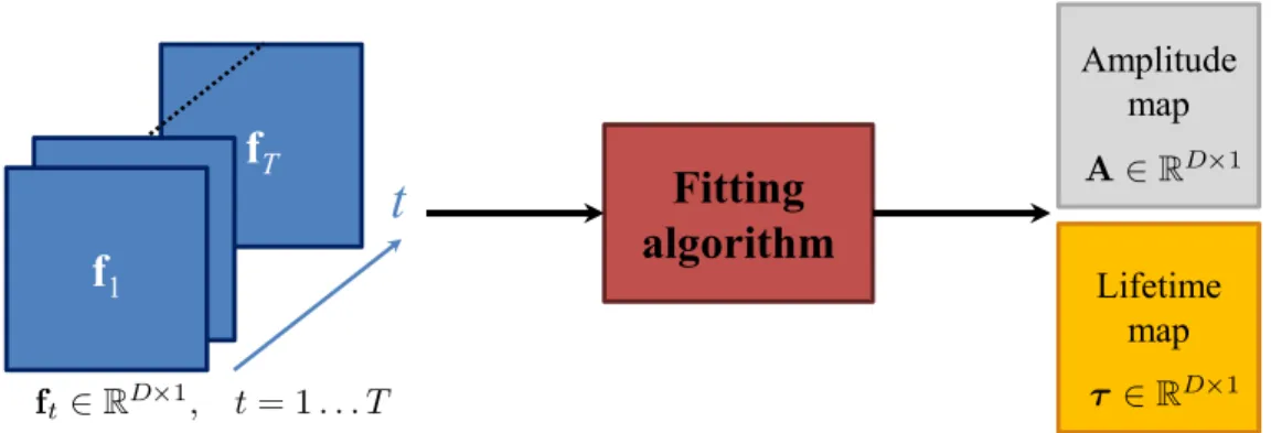
VI.1 Amplitude and lifetime maps obtained by a fitting algorithm using the time-dependent images . . . 94
VI.2 Time-resolved SPC and multispectral time-resolved SPC. . . 95
VI.3 Photo of the considered phantom and SPC images restored from CW measurements or different time-channels . . . 96
VI.4 Time curves obtained from the restored images ft . . . 96
VI.5 Amplitude and lifetime maps obtained by fitting an exponential decay function on the experimental data. . . 97
VI.6 Phantom, CW image and SPC restored images in different time or spectral channels . . 98
VI.7 Spectrum and time curves obtained from the restored images fλ and ft by summing the pixels in each area of the sample for each wavelength/time channel . . . 99
VI.8 Amplitude and lifetime maps obtained from by fitting an exponential decay function on the experimental time curves for each pixel. . . 100
A.1 Considered pattern coded on b = 4 bits . . . 107
A.2 The four bit planes of the pattern displayed in Fig. A.1 . . . 107
A.3 Display time of the four bit planes to recreate a four bit pattern . . . 108
C.1 Montage optique d’une caméra mono-pixel en géométrie de transmission (gauche) ou de réflexion (droit). . . 114
C.2 Schématisation d’une méthode d’acquisition non-adaptative. . . 117
C.3 Schématisation d’une méthode d’acquisition adaptative. . . 118
C.4 Système expérimental du Politecnico di Milano . . . 119
C.5 Montage expérimental à CREATIS . . . 121
C.6 Fonctionnement de la communication entre Matlab et Labview . . . 122
C.7 Acquisition SPC avec ABS-WP sur une image de bioluminescence de souris . . . 125
C.8 Acquisitions experimentales avec la SPC sur la cible de Jaszczak . . . 126
C.9 Image test et courbes du PSNR des images restaurées . . . 131
C.10 Images restaurées par ABS-WP pour les trois techniques de factorisation . . . 132
C.11 Fantôme, image CW et images SPC restaurées dans différents canaux temporels et spectraux . . . 135
C.12 Courbes spectrales et temporelles obtenues depuis les images fλ et ft en sommant chaque pixel des différentes zones de l’objet . . . 136
L
IST OF
T
ABLES
I.1 Summary of the main characteristics of the different SLM technologies.. . . 9
I.2 Summary of the main features of different SPD technologies . . . 10
II.1 Comparison of the main characteristics of the four major categories of acquisition/
restoration schemes for SPI . . . 36
IV.1 Effect of the interpolation technique in our ABS-WP method for different test images . 61
IV.2 Quantization effect in ABS-WP for Le Gall’s wavelet . . . 62
IV.3 Accuracy of the prediction strategy for EWT-ACS technique and our ABS-WP framework 63
IV.4 Obtained PSNRs for different SPC acquisition techniques at two compression rates on
several test images in a noise-free setting . . . 63
IV.5 Average computation time for the different SPC acquisition techniques . . . 64
IV.6 Noisy simulations for different acquisition strategies at a CR of 85% . . . 64
V.1 Number of iterations and computation time for the proposed SNMF algorithm 3 to
converge for several values of (I , D) . . . 82
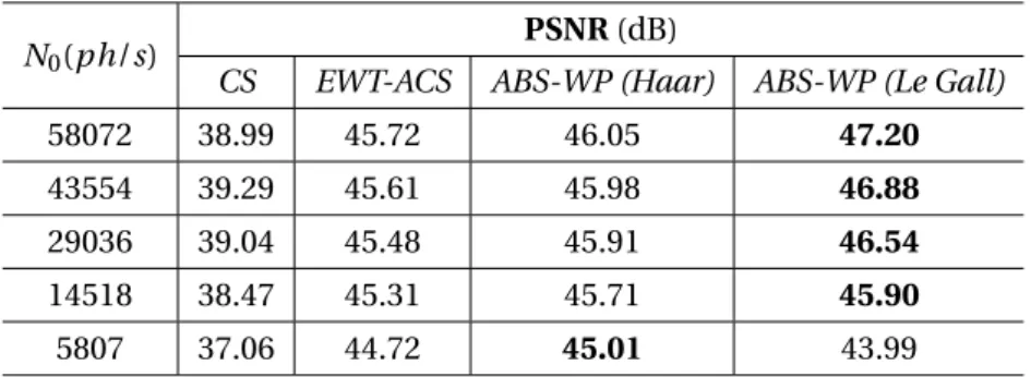
V.2 PSNR values of the SPC restored images for different values of N0andα . . . 84
V.3 PSNR values of the experimental SPC restored images for different values of N0 . . . 87
VI.1 Absorption and emission peaks of the different fluorophores embedded in the phantom 94
C.1 Comparaison des caractéristiques principales des techniques d’acquisition et
restau-ration des images par une SPC. . . 118
C.2 PSNRs obtenus pour différentes stratégies d’acquisition SPC à deux taux de compression125
A
CRONYMS
& A
BBREVIATIONS
Abbreviation or acronym Signification
ABS Adaptive Basis Scan
ABS-WP Adaptive Basis Scan by Wavelet Prediction
BS Basis Scan
ADC Analog-to-Digital Converter
CCD Charge Coupled Device
CMOS Complementary Metal Oxide Semiconductor
CS Compressive Sensing
DCT Discrete Cosine Transform
DMD Digital Micromirror Device
FFT Fast Fourier Transform
LCD Liquid Crystal Display
LCoS Liquid Crystal on Silicon
LED Light-Emitting Diode
MMA Metamaterial Absorber
NMF Nonnegative Matrix Factorization
PMT Photomultiplier
PSNR Peak Signal-to-Noise Ratio
PWM Pulse Width Modulation
RIP Restricted Isometry Property
SFDI Spatial Frequency Domain Imaging
SLM Spatial Light Modulator
SNMF Semi Nonnegative Matrix Factorization
SNR Signal-to-Noise Ratio
SPC Single-Pixel Camera
SPD Single Point Detector
SPI Single-Pixel Imaging
TCSPC Time-Correlated Single Photon Counting
TOF Time-of-flight
N
OTATIONS
& S
YMBOLS
General conventions
x and X are two scalars
x is a column vector
X is a matrix
Mathematical sets
N set of natural elements
Z set of integers
R set of real elements
R+ set of non-negative real elements i.e. {x ∈ R s.t. x ≥ 0}
RK ×1 set of vectors with K real elements
RK ×1
+ set of vectors with K non-negative real elements
RK ×I set of matrices with K rows and I columns of real elements
RK ×I
+ set of matrices with K rows and I columns of non-negative real elements
Vectors and matrices
xnor (x)n n-th element of the vector x
xn n-th column of the matrix X
Xi , j or (X)i , j element at the i-th row and j-th column of X
X|n matrix X deprived of its n-th column
X−n matrix X deprived of its n-th row
x> transpose of the vector x (row vector)
X> transpose of the matrix X
tr(X) trace of the matrix X
I
NTRODUCTION
S
INGLE-PIXEL IMAGING(SPI) is a trendy paradigm that allows the acquisition of images at reaso-nably low cost, and with hardware compression of the data. The architecture of a single-pixelcamera (SPC) indeed consists of only two elements : a spatial light modulator, and a single-point
detector. The key idea is to modulate the image that is observed with a certain pattern, and to collect the corresponding measurements at the single detector. The desired image can then be restored by post-processing the sequence of measures performed with several patterns.
Probably, the first concept of modulation of a light field and collection of the output light on a single detector was reported in1982, through the work ofBen-Yosef et Sirat. They proposed to use the piezoelectric-elasto-optic effect of crystals for modulation, such that the light output is proportional to the Fourier transform of the imaged object. However, at that time, building small and numerous crystals was not as accessible as it is today, andBen-Yosef et Siratonly provided proof of concept with a few crystals, without restoring an image of the object. As a result, the credit for the SPC has been attributed to Rice University, where the first SPC images were obtained almost 25 years later. At
that time, the pioneering idea of compressive sensing (CS) proposed byDonohoin2006opened the
door forTakhar et al.to use the SPC with random patterns in the same year, to reconstruct an image
using a`1-minimization algorithm. Since then, the algorithms have evolved, and new acquisition
strategies have been proposed, and the SPC has found many different applications.
At first glance, having a single pixel can appear to be counterproductive, as the cameras of today embed several millions of pixels. However, several advantages stand out when compared to cameras based on an array of sensors (i.e., CCD or CMOS cameras architectures). First, single-point detectors usually have high efficiency, and can therefore detect weak light intensity changes (Hadfield,2009). In medical applications, this can be very useful, as tissue absorption is usually quite high (Jacques, 2013). Secondly, there is intrinsic compression at the hardware level when using a SPC, which hence needs small storage memory. This is a key advantage in applications where the data rate for
trans-mission would be low, such as remote-imaging applications (e.g., aerospace remote sensing) (Ma,
2009b,a). Finally, a single-point sensor imaging device is usually less expensive than a
sensor-array-based camera. The SPC is therefore well suited to infrared imaging (Shin et al.,2016), where the use of a conventional imaging system that operates at these wavelengths would be costly (Rogalski,2012).
The latter advantages of SPI and the nonionizing nature of the optical imaging makes the SPC an excellent candidate for biomedical imaging applications. For instance, a low-cost, time-resolved imaging system can benefit fluorescence lifetime imaging (Becker,2012), by coupling the point
de-INTRODUCTION
tector with a photon-counting board (Pian et al.,2016a;Rousset et al.,2017b). Adding a spectrometer further allows a complete multispectral time-resolved system to be obtained (Pian et al.,2016b), to supplement the lifetime information of tissues with its spectral content.
The SPC can also be used for imaging through scattering media (Tajahuerce et al.,2014;
Du-ran et al.,2015), for diffuse optics (e.g., skin lesion detection or intraoperative (Gibson et Dehghani,
2009)), for ophthalmology (Lochocki et al.,2016,2017), and to characterize tissue properties using near infrared illumination (Torabzadeh et al.,2017). The SPC has also been successfully transposed on a microscope (Studer et al.,2012;Radwell et al.,2014;Rodriguez et al.,2016). Through exploi-ting several SPC images, this can provide fluorescence molecular tomography and diffuse optical tomography (D’Andrea et al.,2010;Ducros et al.,2013;Pian et al.,2015;Ducros et al.,2016), with applications for molecular imaging and oximetry.
The goal of this thesis is to investigate SPI for biomedical applications. One of the main limi-tations of the SPC in these last cited studies is the speed of acquisition and/or image restoration. In such cases, real-time applications cannot be considered, which rules out interventional imaging (e.g., fluorescence-guided surgery), for instance. Therefore, for biomedical imaging using a SPC, it is necessary to develop specific techniques for acquisition and/or restoration.
To meet the goals of this thesis, a new acquisition strategy for SPC was proposed to reduce the reconstruction times, along with an alternative innovative technique to reduce the acquisition times. The applicability of these techniques for medical imaging is demonstrated for multispectral and/or time-resolved measurements.
This Project was performed as a joint agreement between INSA Lyon and the Physics Depart-ment of the Politecnico di Milano (Polimi), to fund a PhD in each of these institutions (PhD in signal/ image processing for INSA ; PhD in Physics for Polimi). The experimental part was carried out at Po-limi, where a SPC set-up is available. The algorithms and methodologies were conducted within the CREATIS laboratory, which has a long history of dealing with signal-processing techniques for me-dical imaging.
This thesis is divided into six Chapters. The first two Chapters define the general principles of SPI, with the related state-of-the-art in the field. The remaining four Chapters are aimed at answering the problematics of this thesis through different contributions. These Chapters contain some parts of personal publications, as listed in AppendixD.
In ChapterI, the SPC concept is detailed, with several possible implementations. Many different applications for the use of this device are presented, as well as new trends in SPI.
In Chapter II, the mathematical formulation of SPC acquisition is given, to present the pos-sible acquisition/ restoration strategies proposed along the years. Two main categories of techniques stand out : the nonadaptive one, which belongs to the CS framework, and the adaptive ones, where some measurements are performed based on previous measures. This Chapter ends with a conclu-sion as to the state-of-the-art with respect to this thesis problem.
In ChapterIII, the two experimental set-ups involved in the results of the next Chapters are presented. One is the optical set-up at the Politecnico di Milano, to which some improvements were made to control the different instruments. The second system is the one that was implemented in
the CREATIS laboratory.
In ChapterIV, our proposed acquisition strategy is reported, which is referred to as adaptive
ba-sis scan by wavelet prediction (ABS-WP). The wavelet transform for two-dimensional (2D) images is
detailed before defining the proposed acquisition strategy based on fast interpolations and multire-solution approximations. Simulated and experimental data show the efficiency of ABS-WP, compa-red to some of the other SPC acquisition techniques highlighted in ChapterII. This Chapter mainly contains an article published in IEEE Transactions on Computational Imaging in 2017 (Rousset et al.,
2017a).
In ChapterV, a method to halve the number of measurements is proposed. This was designed because patterns with both positive and negative entries cannot be implemented on a spatial light modulator. To deal with this technique, it is common to separate the pattern into its positive and ab-solute negative parts, whereby the subtraction of these two measurements provides the desired mea-surement. This, however, doubles acquisition times, as twice the number of measurements need to be performed. In this Chapter, the problem is formalized, with the demonstration that a semi
nonne-gative matrix factorization (SNMF) algorithm can be used to overcome the experimental constraints,
and therefore to reduce the necessary number of measurements. The data presented in this Chapter were filed as a patent (Rousset et al.,2017c) and submitted to IEEE Transactions on Computational
Imaging (Rousset et al.,2017d).
In ChapterVI, the SPC with the techniques developed in the previous chapters is used for appli-cations that can benefit biomedical imaging. A temporal dimension was added to the SPC to perform fluorescence lifetime sensing, with this lifetime being an important parameter for biologists to as-sess the tissue micro-environment (e.g., pH). These data were presented at the SPIE Photonics West Conference in February 2017 (Rousset et al.,2017b). Then, a spectral dimension was further added, to obtain multispectral, time-resolved measurements. The obtained SPC system coupled to our
ac-quisition strategy of ChapterIVallows complete differentiation between the different components
of the imaged object using the spectral and temporal information. These data will soon be submitted for publication in Optics Express.
CHAPTER
I
T
HE
S
INGLE
-P
IXEL
C
AMERA
Contents
I.1 Concept. . . . 7
I.2 Hardware implementation . . . . 8
I.2.1 Spatial light modulators . . . 8
I.2.2 Single-point detector. . . 9
I.2.3 Numerical converter . . . 10 I.3 Pros and cons . . . . 11
I.3.1 Advantages. . . 11
I.3.2 Disadvantages. . . 12 I.4 Applications . . . . 12
I.4.1 Static imaging . . . 12
I.4.2 Multidimensional imaging . . . 14
I.4.3 Video acquisition . . . 15 I.5 New trends in SPC optical methods . . . . 16
I.5.1 Lensless imaging . . . 16
I.5.2 Emerging photodetectors . . . 16 I.6 Conclusion . . . . 17
C
HAPTER
I
T
HEterm single-pixel camera (SPC) encompasses various hidden ideas and possible opticalim-plementations. The goal of this Chapter is to provide the main concepts behind the SPC, along with its possible hardware implementations defined through the years. Some applications where the SPC is a key element are presented, as well as new trends in the optical field where the use of a SPC is relevant.
I.1 Concept
The theory and data fromDonohoin2006on compressive sensing showed that a signal can be
recovered from only a small number of projections, revisiting the standard Shannon-Nyquist sam-pling theorem. This enabledTakhar et al.to propose a new camera architecture in the same year that was based on a single-point detector, and to build a compressive imaging system (Duarte et al.,2008;
Baraniuk et al.,2014;Miao et Amirparviz,2015). Such a system measures one-dimensional (1D) data
instead of the classical 2D data from a conventional sensor array (e.g., CCD or CMOS cameras). A
spatial light modulator (SLM) is placed between the scene under view – the image – and the single-point (i.e., pixel) detector (SPD), so as to modulate the light coming out of the scene, and to collect
the corresponding projection at the sensor. Sequential measurements are taken with different pat-terns loaded on the SLM, and the post-processing of the data allows image recovery of the scene under view1.
The simplest implementation of the SPC can be schematized as in Fig.I.1, where the SLM is
either a transmissive device or a reflective one, depending on the technology employed. The image of
1. The different acquisition/ restoration schemes for SPI are detailed in the next Chapter.
Spatial light modulator Lens Single point detector Numerical converter Numerical converter Object
FIGUREI.1 – Optical set-up of the single-pixel camera using a transmissive spatial light modulator (left), or a reflective one (right).
CHAPTERI. THESINGLE-PIXELCAMERA
the object/ scene under view is formed in the SLM plane, and a lens is added to focus the modulated light rays on the single-point detector. A numerical converter is used to obtain the numerical data from the single-point detector. Note that the positions of the SLM and the object are interchangeable. If the SLM is placed before2the object, it is said to modulate the light in illumination, if it is placed after, the detection side is modulated.
I.2 Hardware implementation
Many different hardware implementations of the SPC have been proposed through the years. Depending on the desired applications, specific technologies should be chosen to obtain the best
from the SPC. This section provides some examples3of the most used SLM and SPD technologies,
as well as the different means to obtain numerical measurements to process these data.
I.2.1 Spatial light modulators
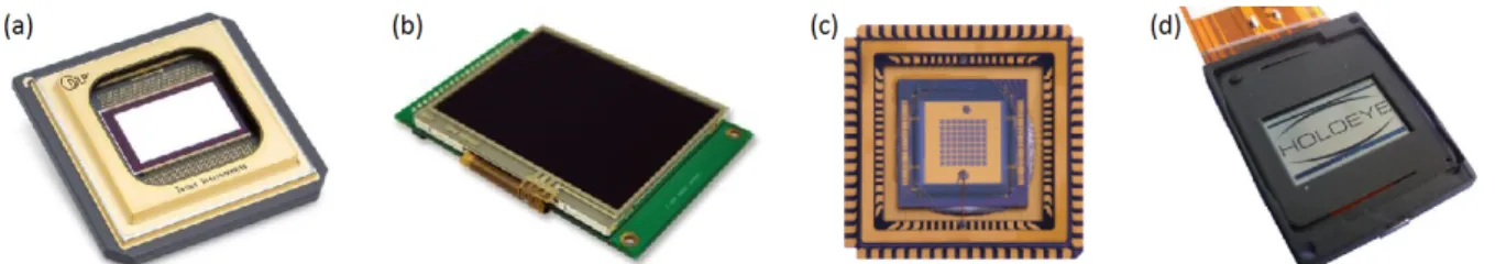
DMD The original work ofTakhar et al.andDuarte et al.used a digital micromirror device (DMD ;
Fig.I.2a), which was invented byHornbeckat Texas Instruments in 1987. Such a device comprises
thousands of tiny mirrors that are arranged in a matrix array of size H × W . The value of H (resp.
W ) typically ranges from 768 (resp. 1024) to 1600 (resp. 2560), with a mirror pitch of 7 to 14µm,
which depends on the model. Each of the mirrors is independently controlled and can be tilted into two positions. At +12°, the so-called ON state reflects the light towards the detector, and is therefore collected by the detector. At −12°, the OFF state sends the light in the opposite direction. The DMD can thus load binary patterns where a 0 corresponds to the OFF state and a 1 to the ON state. The DMD also offers the possibility to load 8-bit gray-level patterns using the principle of pulse width
modulation (PWM). For this, a single 8-bit pattern is separated into the corresponding 8 binary bit
planes. Each of these is associated to a particular display time that is a multiple of a power of 2, to
recreate an 8-bit pattern. More details about the PWM for DMD are given in AppendixA.
LCD In2013,Huang et al.used a liquid crystal display (LCD ; Fig.I.2b) panel as a transmissive4 SLM. This kind of device uses polarizing filters, and the properties of the liquid crystal orientations were tuned using an electric field. Each of the H ×W pixels (i.e., crystals) of this system are arranged in a matrix and can also take two states. The difference with the DMD is that the ON state corres-ponds to a transparent element, which lets the light pass to the detector, whereas the OFF state represents an opaque element. Values for H and W cover a vast range, with LCDs encountered in everyday life, from calculators to television screens.
MMA Watts et al. in2014proposed an in-house SLM defined as a liquid crystal metamaterial5
absorber (MMA ; Fig.I.2c) SLM. A maximum of 8 × 8 pixels are available in their design, where the properties of the metamaterials are each individually controlled by applying a bias voltage. As for
2. In the direction of the light 3. As a nonexhaustive list
4. Reflective LCD devices also exist, but are not presented here as they are outperformed by DMDs, due to their higher refresh rates
I.2. Hardware implementation
FIGUREI.2 – Examples of spatial light modulators. (a) Digital micromirror device. (b) Liquid crystal display. (c) Metamaterial absorber. (d) Liquid crystal on silicon. The images were extracted and adapted from Texas Instruments website (a), STMicroelectronics website (b),Watts et al.(2014) (c), and Holoeye website (d).
the DMD, each pixel is reflective and can take two states [0,1]. This set-up, however, allows the use of patterns with [-1,0,1] values through modulation of the pixels +1 in phase and the pixels −1 out of phase with a reference.Watts et al.(2014) showed that the MMA SLM is well adapted and efficient for terahertz imaging.
LCoS Unlike the previous intensity modulators, a liquid crystal on silicon (LCoS ; Fig.I.2d) SLM can modulate the light phase. As for the LCD, an electric field tunes the crystals to create binary patterns. Such a device was, for instance, used inClemente et al.(2013) to perform compressive holography. Note that a LCoS device can be used along with polarizers to recreate an intensity-based SLM.
TableI.1summarizes the principal characteristics of the different SLM technologies. The use of a DMD for SPC is by far the most common, as it offers fast refresh rates and is easy to set up.
Technology Geometry Modulation Refresh rate Number of pixels Pixel pitch Active area DMD Reflective Intensity 32 kHz 1600 × 2560 7 − 14µm ∼ mm2
LCD Transmissive Intensity 50 − 600 Hz 4320 × 7680 ∼ 50 to 300 µm mm2to m2
MMA Reflective Intensity ∼ kHz 8 × 8 ∼ 250 µm 4.8 mm2
LCoS Reflective Phase ∼ 60 Hz 768 × 1024 ∼ 20 µm ∼ mm2 TABLEI.1 – Summary of the main characteristics of the different SLM technologies.
I.2.2 Single-point detector
Photodiode A photodiode (Fig.I.3, left) is a semi-conductor element that can receive photons and
convert them into an electrical current. Photodiodes are usually made of a PN junction6 or a PIN
junction7. The photons of the light rays arriving at the photodiode are absorbed, and if their energy is over a certain value, they can move to the conductive band, which induces an electric current. Different materials can be used to create a photodiode, each of which imparts certain properties to the detector, and these are summarized in tableI.2.
Photomultiplier The photomultiplier (PMT ; Fig. I.3, right) promotes the conversion of the de-tection photons into an electrical current. It comprises a photocathode8, a focusing electrode,
dy-6. A junction where the doping changes sharply, going from a positive (P) doped side to a negative (N) one 7. PN junction with an undoped intrinsic semiconductor in between
CHAPTERI. THESINGLE-PIXELCAMERA
FIGUREI.3 – Examples of single-point detectors, as a photodiode (left) and a photomultiplier (right). The images were extracted and adapted from ThorLabs website (photodiode) and Horiba Scientific website (PMT).
nodes9, and a final anode, all of which are embedded in a vacuum tube. When a photon reaches the
photocathode, this releases an electron that passes to the focusing electrode. There, the electron is accelerated toward the dynodes, to which a certain electric tension is applied, to multiply the elec-tron. The bigger the tension applied to the dynodes, the more the electrons are multiplied. Finally, the anode collects the electrons as an electric current.
TableI.2summarizes the principal features of the different single-point detectors10. Photodiodes are mostly used as they are easy to use and cheap, due to their simple structure, and they cover a wide spectral range.
Technology Material Spectral range Active area Dark current Photodiode
Silicon 200 nm - 1100 nm ∼mm2- cm2 ∼ 1 - 600 nA
Indium Gallium Arsenide 800 nm - 1700 nm ∼mm2 ∼ 50 nA Germanium 800 nm - 1800 nm ∼mm2 ∼ 1 µA
Photomultiplier
Multialkali 160 nm - 900 nm ∼cm2 ∼ 3 nA Bialkali 185 nm - 650 nm ∼cm2 ∼ 0.1 nA Indium Gallium Arsenide 185 nm - 1010 nm ∼mm2 ∼ 1 nA
TABLEI.2 – Summary of the main features of the different SPD technologies. The data are mainly taken from ThorLabs and Horiba Scientific websites.
I.2.3 Numerical converter
Regardless of the kind of detector used, the measurement that is wanted by the user needs to be a numerical measurement in order to process the SPC data. Several technologies can be used to perform such a conversion.
ADC The electrical signal provided by the photodiode or PMT can be digitized using an
analog-to-digital converter (ADC). This device samples the current intensity (or tension) at a given frequency,
whereby the sampled value is proportional to the magnitude of the intensity (or tension). ADCs are widely available and their features should be chosen according to the needs of the single-point de-tector (i.e., sampling rate, input voltage/ intensity, number of bits).
9. Electrodes in a vacuum tube used to multiply electrons 10. As a nonexhaustive list
I.3. Pros and cons
TCSPC Some single-point detectors11can be coupled to a time-correlated single photon counting (TCSPC) board, which should be used with a pulsed laser, to illuminate the scene under view. TCSPC provides the number of photons, although due to the reference laser pulse, this is done for different time channels according to the time-of-flight of the photons. In this case, the SPC measurement is not simple scalar data, but a vector of scalar measurements for each time channel.
I.3 Pros and cons
The hardware implementation of the SPC provides some insight and ideas about the possible pros and cons of a SPI system. These are detailed in the next paragraphs.
I.3.1 Advantages
As mentioned in theIntroduction, several advantages stand out when using a SPC as an imaging
system compared to traditional digital cameras with arrays of sensors.
One of the most important advantages is the optical compression at the hardware level. Cameras of today acquire tens of megapixels, which results in huge computer files. As a consequence, most images are compressed to reduce their size on the disk, and to be suitable for transfer (e.g., by email ; for websites). This throws away roughly 80% of the information that was acquired with the conven-tional camera. With SPC, the idea is to directly perform the compression during the acquisition, so that only the remaining 20% of the useful information is acquired. As well as reducing the memory storage, this acquisition of only a few numbers of measurements reduces the energy consumed, by a factor of 5 according to the example above. Small memory storage and power consumption are key elements for devices where the storage unit and the battery life are limited (e.g., robots, cellphones). As shown in tableI.1and tableI.2, the active area of most SLMs and SPDs are in the mm2range, which therefore opens the door to very compact devices. In addition, restoration of SPC images wi-thout the lens of Fig.I.1has been demonstrated at Bell Laboratories (Huang et al.,2013), which is a big step toward SPC miniaturization.
Last but not least, the price of a SPC is relatively low compared to traditional cameras. First, while visible CCD or CMOS cameras are inexpensive due to well-controlled and cheap silicon technology, silicon sensors are not as efficient outside the visible range, and another component needs to be used. In this sense, the SPC has the huge advantage, in that for a system working in the ultravio-let or infrared, it uses a SPD that can have high efficiency (Hadfield,2009) and is less costly than a sensor array (Rogalski,2012). Secondly, a SPC can be easily turned into a hyperspectral/ multispec-tral camera by replacing the detector with a single-point spectrometer. Such spectrometers provide nanometer spectral resolution for some thousands of euros, where conventional imaging systems with similar resolution would be about ten-fold more expensive. Thirdly, the cost gain is also impor-tant if the single-point detector is coupled to TCSCP to obtain a time-resolved (TR) imaging system. Spectrometery and TCSPC can finally be used together to build a multispectral/ hyperspectral time-resolved device. Hence, SPI provides low-cost systems with high spatial, temporal, and/or spectral resolution that is difficult to achieve with conventional arrays of sensors.
CHAPTERI. THESINGLE-PIXELCAMERA
I.3.2 Disadvantages
While a conventional digital camera simultaneously acquires each pixel of the image, a SPC needs to perform sequential measurements, which inevitably makes it slower than traditional ca-meras. The speed of acquisition is limited by the SLM, the SPD, and/or the device for numerical
measurements. For instance, tableI.1shows that at the present time12, the maximum frame rate
for the available SLMs is 32 kHz. If, for example, a 1024 × 1024 pixels image is acquired and 20% of the number of pixels are acquired in terms of the measurement, this leads to a minimum of 10242× 0.2/32000 ≈ 6.6 s for the acquisition time, whereas a conventional camera would take a few hundred milliseconds.
A second disadvantage that is also linked to the speed of SPI is the post-processing of the
se-quence of measurements to obtain the desired image. As will be shown in ChapterII, some image
restoration techniques take less than a second, but others can take up to minutes, depending on the resolution of the image and the number of sampled measurements.
Overall, at the moment, SPI is not well suited for capturing high-resolution images, as both ac-quisition times and restoration times increase with the number of measurements.
I.4 Applications
Owing to its numerous advantages, the SPC has found several applications since the first recove-red images ofTakhar et al.in2006. Some examples are given below, to which the medical applications
mentioned in theIntroductioncan be added.
I.4.1 Static imaging
Color imaging Color images were proposed in the first studies on SPCs byDuarte et al.in2008. For this, to get three measurements for one pattern, they used RGB filters placed in front of the photo-diode. The restoration of the image in each RGB canal led to a color image. InWelsh et al.(2013), a full-color SPC was presented using a dichroic beamsplitter. This decomposed the white light into three outputs (i.e., red, green, blue) and three photodiodes collected the resulting light. One image per color channel can therefore be restored so as to get a color image (see Fig.I.4, left).
Salvador-12. Refresh rates of DMDs have kept on increasing since their creation
FIGUREI.4 – Examples of static imaging using a single-pixel camera. Left : color image of a dinosaur scene adapted fromWelsh et al.(2013). Right : visible (left) and short-wave infrared (right) images obtained from the single-pixel–camera-based microscope ofRadwell et al.(2014).
I.4. Applications
Balaguer et al.(2016) used the same approach asDuarte et al., but with one photodetector. The
difference lies in the use of a color wheel with RGB filters on the illumination side, and not on the detection side.
Infrared imaging Radwell et al. (2014) designed a SPC-based microscope to image both in the short-wave infrared and the visible spectrum (see Fig. I.4, right). For this, a short-wave infrared source was used, and the two DMD arms (i.e., the ON, OFF states) were coupled to two different detectors, a visible-light-sensitive sensor, and an infrared-sensitive sensor. A similar idea was used
byEdgar et al.(2015), where visible and infrared images were recorded. The light emitted from the
DMD was split into a short-wave-dependent beam and a visible beam, using a hot mirror13.Shin
et al.(2016) illuminate the object with a near-infrared tunable continuous-wave laser that was cou-pled to a single-mode fiber, to illuminate the object with random speckled patterns14(Shin et al., 2017). A sensitive infrared photodiode was used as the detector, to obtain an image of the object in the infrared. Recently, inGibson et al.(2017), methane gas leaks were observed using an infrared SPI system, which showed the potential of infrared imaging based on SPC.
Ghost imaging Ghost imaging systems usually combine a CCD camera that does not see the object
(hence the term ghost) with a single-point detector on the object path, to get the image of the obser-ved object. In2008, with the advances in SPC,Shapiroshowed that ghost imaging was possible using
only the SPD. The idea of using simply the SPC arm was taken up byAßmann et Bayer(2013) and
thenYu et al.(2014a), who used different computational approaches. InOnose et al.(2016), a new
hardware technology was used for ghost imaging, with an array of light-emitting diode (LED) lights that performed modulation of the illumination to recreate a SPI system.
Terahertz imaging Shortly after the first SPC images,Chan et al.in2008showed that the ideas of SPI could be applied to terahertz imaging. A terahertz transmitter was used to illuminate the object, the SPC patterns were printed on printed-circuit boards, and a single terahertz receiver served as the detector.Ma et al.(2012) considered the use of a Nipkow disk to create a SPC-based imaging sys-tem suited for terahertz imaging. A terahertz SLM was created byShrekenhamer et al.(2013) through photoexcitation of semiconductors that were coupled to a classic DMD, and this was used to obtain a SPC terahertz imaging system. The same authors, asWatts et al.(2014), changed their design slightly to use the single MMA SLM presented in I.2.1as proof for a terahertz SLM. InFursich et al.(2016), a system based on a single terahertz detector and frequency modulated continuous wave radar was reported. This SPC-based imaging system radar can be used by airport security for weapon
detec-tion. A single-pixel terahertz system based on a metal mask structure was also presented inDuan
et al.(2016), which allowed imaging at 1.75 THz.
Microscopy InStuder et al.(2012), a conventional microscope was transformed into a compressive microscope using the principle of compressive sensing ; this was shown to successfully image fluo-rescent beads, cells, and tissues. In the study ofRodriguez et al.(2016), a microscope was created to
13. Mirror reflecting the infrared light and letting past the visible light 14. Note that in this particular design, no SLM was used
CHAPTERI. THESINGLE-PIXELCAMERA
FIGUREI.5 – Examples of multidimensional imaging using a single-pixel camera. (a) Object used for mul-tispectral imaging inBian et al.(2016b). (b) The corresponding 10 single-pixel camera restored images in different spectral channels, from 450 nm to 650 nm. (c) Scene imaged inSun et al.(2016a). (d) Recovered three-dimensional image from the single-pixel camera measurements.
image in both reflective and transmissive geometries based on SPC. A DMD was used for illumina-tion, and two PMTs served to create two SPCs, one in reflection and one in transmission. The dual
infrared/ visible SPC ofRadwell et al.for infrared imaging was also mounted on a microscope, to
image objects of a few hundreds ofµm in size (see Fig.I.4, right).
Telescopic imaging A telescopic system was used inYu et al.(2014b) to image an object from 2 km away. They showed that reduction of the measurements could be achieved using both arms of the DMD (i.e., the ON and OFF beams) with two PMTs. Their set-up had the advantage of having a large field of view over long distances, and could be used for applications in remote target imaging.
Digital holography Digital holography was reported byMartínez-León et al.(2017), who used phase-structured illumination and bucket detection, which allowed them to image complex amplitude ob-jects. The advantages in this design were the use of only one phase SLM, and an improvement by a factor of two for the signal-to-noise ratio.
I.4.2 Multidimensional imaging
Multispectral/ hyperspectral imaging InMagalhaes et al.(2012), a hyperspectral imaging system based on SPC was proposed. The single-point detector of the SPC was replaced by a spectrum ana-lyzer that could reach a spectral resolution of 10 pm. A hyperspectral spectrometer coupled to a SPC was also used inHahn et al.(2014), but with a different acquisition strategy at the software level. A pa-tent for a dual spectral SPC acquisition set-up has also been filed by Xerox Corporation (Bernal et al., 2015), which also filed a patent for hyperspectral imaging using a Fabry-Perot filter and a single-point detector (Nystrom et al.,2016). In the recent studies ofBian et al.(2016b), a multispectral imaging system that used a single bucket detector was reported to provide a high-sensitivity imaging system (see Fig.I.5a, b). They used classical SPC architecture with a DMD, but further modulated their data
I.4. Applications
with a rotating film that allowed for sinusoidal modulation in the spectral dimension. A spectrometer based on SPC was reported inStarling et al.(2016), where their design measured both the absorp-tion and emission spectra with 90% reducabsorp-tion of the dataset used by a commercial spectrometer. In
Li et al.(2017), a system that used only one photodiode for multispectral imaging was presented. In
their set-up, the light emitted from the object went to a spectral splitter that created eight different beams that went to eight different areas of the SLM, and then everything was collected on the pho-todiode. As the areas of the SLM were encoded with their own particular patterns, post-processing of the measurements allowed the eight images in eight different spectral channels to be recreated.
Three-dimensional imaging InSun et al.(2013), a projector illuminated a scene with random spe-ckle patterns, and four photodetectors were placed at different angles to collect the outgoing light. Post-processing of the data from the four single-point detectors allowed reconstruction of a 3D image of the scene. The same group extended their data to 3D video imaging inZhang et al.(2016)
andSun et al.(2016a) (see Fig.I.5c, d). InYu et al.(2015), the depth information and 3D
reflecti-vity of the scene were reconstructed using simple algebra. A Fourier-based technique to retrieve 3D
information was presented inZhang et Zhong(2016). The depth information was modulated by
well-chosen patterns in illumination and collected by the SPD, which enabled 3D reconstruction of the object with Fourier analysis.Salvador-Balaguer et al.(2016) performed stereoscopic color imaging using a color projector15for illumination from two different angles, to create a stereoscopic pair.
Time-resolved imaging A time-resolved photodetector was used byKirmani et al.(2011) to per-form time-of-flight measurements using a SPC. The exploitation of this time-of-flight for each pixel
of the image provided a depth map for the scene under view. The same idea was presented by
How-land et al.(2013) using a SPC with a PMT as a detector coupled to a TCSPC board. InDai et al.(2016),
the same technology was used with a different acquisition strategy, to obtain both the reflectivity and the depth map.
I.4.3 Video acquisition
Judging by the number of publications in recent years, video imaging is a growing application for
SPC. A recent review of state-of-the-art compressed video sensing techniques was given inBaraniuk
et al.(2017). Although SPC acquisition and restoration schemes can be relatively slow, the idea was to exploit the temporal redundancy to reduce the number of measurements, and thus to speed up both the acquisition and restoration times. Such approaches therefore made video recovery compu-tationally more demanding than static image restoration.
To compress further by exploiting temporal redundancy, different techniques have been propo-sed, such as the methods based on motion estimation inSankaranarayanan et al.(2015,2016) (see Fig.I.6) andGoldstein et al.(2015), and minimization of the image spatial-curvature inEdgar et al. (2015), with techniques that mimicked animal imaging inPhillips et al.(2016). A different approach for image acquisition/ restoration was used byZhang et al.(2016) that allowed faster image reco-very. InGibson et al.(2017), the same group proposed a similar approach for video surveillance of
CHAPTERI. THESINGLE-PIXELCAMERA
FIGUREI.6 – Examples of video imaging of a red toy car that was moving from left to right using a single-pixel camera adapted fromSankaranarayanan et al.(2015). Ground truth images (top row) and single-pixel camera recovered video images (bottom row) are shown.
methane gas leaks. A time-varying 2D ultrasonic field was encoded inHuynh et al.(2016) to enable video rate imaging of ultrasound fields.
I.5 New trends in SPC optical methods
In recent years, some new ideas and optical system designs have been reported in the optical field, to simplify imaging systems or make the best use of new materials. The use of a SPC for some of these new trends might be relevant, and is presented in the next paragraphs.
I.5.1 Lensless imaging
Lensless imaging has become an important topic in optics over the last decade, as it offers large fields of views with compact imaging systems (Allier et al.,2010;Ozcan et McLeod,2016;
Boomi-nathan et al.,2016). New imaging systems without focusing lenses have been designed, such as the
PicoCam (Stork et Gill,2013) and the FlatCam (Asif et al.,2015b,a;Boominathan et al.,2016). In2013, Bell Laboratories proposed a SPC architecture without a lens inHuang et al.(see Fig.I.7, left). Their design comprised an LCD screen as SLM, and a photovoltaic sensor. Here, no physical image was formed before it was digitally captured. The use of a SPI in this design reduced the size, cost, and complexity of the final camera architecture.
I.5.2 Emerging photodetectors
In the last decade, new technologies and materials have allowed for the creation of new photode-tectors with improved features. For instance, carbon nanotubes (Chen et al.,2011,2014), and more
I.6. Conclusion
FIGUREI.7 – Lensless single-pixel camera images adapted fromHuang et al.(2013) (left), and the single-pixel camera image obtained with a carbon nanotube photodetector adapted fromChen et al.(2014) (right).
recently, graphene (Li et al.,2016), have been used as photodetectors to enhance some or several SPC possibilities.
Owing to their opto-electronic properties, carbon nanotubes can be used as a photodetector that outperforms most infrared detectors. The high surface-to-volume ratio of carbon nanotubes can increase the signal-to-noise ratio, and photon scattering suppression and size shrinking can reduce the noise associated with these detectors (Kuo et al.,2001). As the fabrication of large-scale carbon nanotube photodetectors is difficult, Chen et al.(2011,2014) proposed to use the sensor in a SPI system, to extend the possible applications of the SPC with classic photodetectors (see Fig.I.7, right). Since its first discovery in 2004, graphene has been investigated more and more by laboratories due to its remarkable properties. Among these, graphene is stronger than any steel, and it is as good an electricity conductor as copper. Graphene can be made luminescent, its transmittance is almost wavelength independent, and it can be used as a saturable absorber (Bonaccorso et al.,2010). Com-bining its electronic and optical properties, graphene-based photodetectors can convert received light into voltage in an extremely short time (Xia et al.,2009).Li et al.showed in2016that such a detector can be used for SPI. This showed the potential of graphene, which might allow high-speed imaging in the future, as it can convert light into voltage at high frequency.
I.6 Conclusion
This Chapter presents the main ideas behind the SPC and its possible hardware implementa-tions, which can take on various forms, both in transmissive and reflective geometries. The many advantages of the simple set-up, and particularly the low-cost aspect of using a single-point detec-tor, has made SPI an emerging imaging technique over the last decade. Based on the numerous ap-plications presented in this Chapter, the SPC should still remain an attractive topic in future years.
While this Chapter presents the hardware side of the SPC, several essential questions related to its software side remain unanswered. How can an image be obtained from single-point measurements ? What are the mathematical tools and concepts behind this ? These questions are addressed in the following Chapter, along with the possible acquisition/ restoration scheme for SPCs that have been proposed since2006.
CHAPTER
II
A
CQUISITION
/ R
ESTORATION
S
CHEMES FOR
S
INGLE
-P
IXEL
I
MAGING
Contents
II.1 Mathematical formulation . . . . 21
II.1.1 Simple modeling . . . 21
II.1.2 Real measurement modeling . . . 22
II.1.3 Problem . . . 22 II.2 Compressive sensing . . . . 23
II.2.1 Acquisition/ restoration in the compressive-sensing framework . . . 23
II.2.2 Examples of a compressive-sensing-based single-pixel camera . . . 25
II.2.3 Pros and cons . . . 25 II.3 Basis scan . . . . 25
II.3.1 Acquisition/ restoration in the basis-scan framework. . . 26
II.3.2 Examples of basis-scan-based single-pixel cameras. . . 27
II.3.3 Pros and cons . . . 28 II.4 Adaptive basis scan . . . . 29
II.4.1 Acquisition/ restoration in an adaptive basis scan framework. . . 29
II.4.2 Examples of adaptive-basis-scan-based single-pixel cameras . . . 31
II.4.3 Pros and cons . . . 33 II.5 Hybrid methods. . . . 33
II.5.1 Examples of hybrid techniques . . . 33
II.5.2 Pros and cons . . . 35 II.6 Conclusion . . . . 36