E L S E V I E R Magnetic Resonance Materials in Physics, Biology and Medicine 8 (1999) 27-32
M A G M A
Magnetic Resonance Materi.,ds in Physics, Bioktg~" 'and MedicineIn vitro image characteristics of an abdominal aortic stent graft: CTA
versus 3D M R A
Paul R. Hilfiker, Harald H. Quick, Michaela Schmidt, Joerg
F. D e b a t i n *
Institute of Diagnostic Radiology, Unirersity Hospital Zurich, Ramistr. I00, CH-8091 Zurich, Switzerland
Received 13 July 1998; received in revised form I I September 1998; accepted 17 November 1998
Abstract
Percutaneous stent-grafting is increasingly employed as a less invasive alternative to surgery for the treatment of infrarenal abdominal aortic aneurysms. It requires long-term imaging follow-up, to document the structural integrity of the device, to exclude perigraft channels and endograft leakages, as welI as the shrinkage of the aneurysmal sac. The expectation of severe stent induced artifacts and safety concerns have prevented 3D MRA from being used. The purpose of this in vitro study was to investigate the imaging characteristics of a bifurcated stent graft with 3D MRA (3D Fourier transform fast spoiled GRE) at 1.5 T in comparison to those of CTA. Measurement of the stent wall thickness and luminal diameter were made on a agar gel embedded stent graft at five locations on both CTA and MRA images. The stent graft was depicted as a dark ring on MR images. Wall thickness measurements at the five locations of the stent graft overestimated the true stent thickness, while luminal diameters were slightly underestimated. Measurement differences between MR and CT were not statistically significant (P = 0.67; P = 0.85). Artifacts emanating from the platinum markers were considerably less severe on the MR-images. A wider area of signal loss was seen only at the insertion of the iliac stent leg into the aortic stent portion due to the overlap of two radio-opaque platinum markers. 3D MRA images should permit a comprehensive assessment of the arterial lumen, and of perivascular tissues. 9 1999 Elsevier Science B.V. All rights reserved.
Keywords:
Magnetic resonance (MR); Artifact; Vascular studies; Grafts; Interventional procedure; Stents; Prosthesis1. Introduction
Percutaneous stent-grafting is increasingly employed as a less invasive alternative for the treatment of in- frarenal a b d o m i n a l aortic a n e u r y s m s [1-3]. In con- trast to surgery, a n e u r y s m a l stenting requires long-term imaging follow-up, to d o c u m e n t the struc- tural integrity of the device as well as the shrinkage of the aneurysmal sac [4]. T h e expectation of severe stent induced artifacts a n d safety concerns have pre-
* Corresponding author. Tel.: + 11-1-2555193; 2554443.
E-mail a&lress: [email protected] (J.F. Debatin)
fax: + 11-I-
vented 3D M R A from being used for this follow-up imaging [5].
The purpose of this in vitro study was to compare the imaging characteristics o f an aortic stent graft on 3D M R A images to those seen o n C T images.
2. Material and methods
2.1. Stent graft
A commercially available stent graft, used routinely in o u r i n s t i t u t i o n (Vanguard; Boston Scientific, Oak- land, N J) was studied. T h e self-expanding endopros- thesis is composed of a nitinol frame annealed into a t u b u l a r zigzag configuration by a 7-0 polypropylene
28
P.R. Hi(fiker et al. / Magnetic Resonance Materials m Physics. Biology amt Medicine 8 (1999) 27-32t h r e a d [6] and covered with a 0.1 m m woven-polyester
fabric. The b i f u r c a t e d device has two components: the
larger c o m p o n e n t consists o f an aortic graft with a
short, 10 m m wide iliac b r a n c h , into which the smaller
c o m p o n e n t is inserted [7]. B o t h ends o f the stent frame,
as well as the j u n c t i o n between the two sections are
tagged with a p l a t i n u m m a r k e r allowing p r o p e r device
p o s i t i o n i n g u n d e r fluoroscopic guidance. The stent used
in these experiments was 153 m m long with an aortic
d i a m e t e r o f 24 m m a n d an iliac diameter o f l0 m m
(Fig. 1).
2.2. In vitro S t e n t # n a g i n g
The inflated stent graft was e m b e d d e d into agar-gel,
spiked in a c o n c e n t r a t i o n o f 1:20 with b o t h G d - D T P A
(Magnevist; Schering, Berlin, G e r m a n y ) to simulate the
i n t r a l u m i n a l aortic signal d u r i n g 3D M R A , as well as
i o d i n a t e d c o n t r a s t (Visipaque, 270 mg 1 m l - l , Ny-
corned I m a g i n g AS, N o r w a y ) to simulate the a p p e a r -
ance o f c o n t r a s t - e n h a n c e d a o r t i c blood.
All M R imaging was p e r f o r m e d on a 1.5 T M R
scanner (Signa EchoSpeed; G E M S , Milwaukee, Wis)
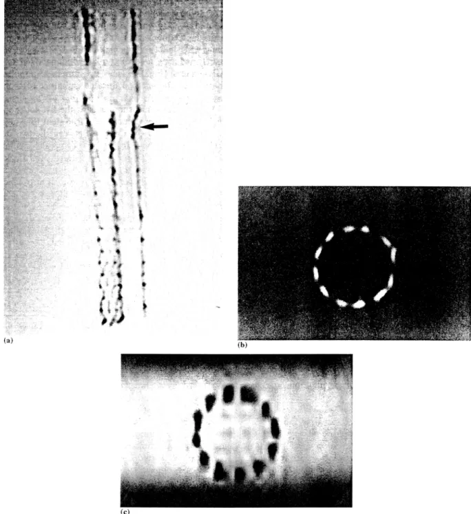
Fig. 1. Stent graft used for the endoluminal treatment of infrarenal aortic aneurysms (Vanguard; Boston Scientific, Oakland, N J). (a) Frontal view.
The graft has two components that are inserted separately and subsequently joined: the primary component consists of an aortic and iliac
stent-graft with an attachment site for the secondary component, which is placed in the contralateral iliac artery. Junction of the two stent
components (arrow). (b) View in the stent from the aortic part.
P.R. Hilfiker et al. / Magnetic Resonance Materials in Physics, Biology and Medicine 8 (1999) 2 7 - 3 2 29
using an anteroposterior phased-array surface coil for
signal reception. Based on axial multiphase gradient-re-
called-echo (ORE) localising images, a 3D Fourier
transform fast spoiled G R E acquisitions was acquired
consisting of 44 contiguous 2.5 mm coronal sections.
The sequence employs a sampling bandwidth of + 62.5
kHz, a T R / T E of 4.0/1.9 ms and a flip of 40 ~ Com-
bined with a 24 x 24 cm 2 field-of-view (FOV), a 256 x
192 matrix provided an in-plane resolution of 0.9 x 1.2
m m 2. Wall thickness and luminal diameter measure-
ments were based on axial reconstructions.
CT imaging was performed on a 'Somatom Plus 4'
scanner (Siemens Medical Systems, Erlangen, Ger-
many), using the following parameters: 3 mm collima-
tion width, 6 m m table speed (1:2 pitchratio), 240 mA
and 120 kV. Helical CT scanning covered the whole
stent-graft. Wall thickness and luminal diameter mea-
surements were based on transaxial images, which were
reconstructed every 3 m m (increment 3).
2.3. In vitro Stent image analysis
The stent-graft was rendered dark on MR images,
and bright on the CT images. Stent wall thickness and
diameters were measured on axial images at five identi-
cal locations:
1. proximal aortic portion traversing the platinum
marker;
2. center of the aortic portion;
3. proximal iliac portion traversing the platinum
marker;
4. center portion of the iliac legs (left and right
separately);
5. distal iliac portion traversing the platinum marker.
On each of the five selected images, wall thickness
was measured at four points, each spaced 90 ~ from one
another. At each location, two orthogonal luminal di-
ameters, each connecting two opposite points were also
measured. Measurements were based on signal intensity
plots drawn orthogonal to the tangent of each measure-
ment point. The luminal stent diameter was defined as
the distance between the two inner points of half maxi-
mum/minimum signal intensity; wall thickness was
defined as the distance between the inner and the outer
point of half maximum/minimum signal intensity.
Statistical analysis of the CT and MR data was based
on the paired Student's t-test, using a cut-off of 0.05 to
signify statistical significance.
3. Results
The stent graft was well delineated on both M R and
CT images. Reflecting its increased density, the stent
was depicted as a bright ring on CT images. On M R
images the stent structure created a signal void and was
thus displayed as a dark ring. The low level of artifact
on the 3D G R E images allowed the boundaries of the
stent to be clearly seen (Fig. 2). The woven wires of the
stent-graft were visible against the contrast enhanced
agar-gel. Platinum markers exhibited artifacts resem-
bling a starburst or ring pattern on CT images, whilst
merely inducing a focally enlarged signal void on the
M R images (Fig. 3). The 0.1 m m woven-polyester
fabric could not been delineated on either MR or CT
images.
Wall thickness measurements at the five locations of
the stent graft overestimated the true stent thickness on
both the MR and CT images. Between the two image
sets, measurements revealed no statistically significant
differences (P = 0.67) (Table 1). Merely wall thickness
measurements obtained at the junction of the two stent
components in the proximal portion of one iliac leg
revealed a statistically significant difference: the plat-
inum-induced artifacts simulated a wider appearance
on M R images compared to CT images ( P = 0.02).
Reflecting the overestimation of wall thickness, luminal
diameters were slightly underestimated on both MR
and CT images. Measurement differences between MR
and CT were not statistically significant (P = 0.85).
4. Discussion and conclusion
Currently spiral CTA is being propagated as the
modality of choice for stent-graft follow-up [4]. Spiral
CTA is fast, permitting coverage of a long vascular
segment during the intra-arterial phase of a single intra-
venous contrast injection. The technique is non-inva-
sive, has been shown to be more sensitive in the
detection of perigraft flow than DSA, and permits
reproducible stent-retated measurements [4]. These
measurements do appear to be fraught with some errors
however, as documented by this study. Stent wall thick-
ness was overestimated and luminal stent diameters
were underestimated. In addition, the presence of metal
can corrupt image quality in the form of starburst
artifacts as shown by the stent platinum markers.
The results of this 'in vitro' experiment show that
these stents can also be imaged with MRA. The very
short echo time of less than 2 ms, inherent to the fast
3D G R E acquisition, limits stent-related susceptibility
artifacts, which are associated with other sequences
[8-10]. The nitinol frame filaments of the stent-graft
are identifiable on the individual sections and reforma-
tions as distinct areas of signal void, allowing for a
detailed assessment of stent structure.
Similar to CTA, 3D M R A images tend to slightly
overestimate the width of the stent graft wall. Based on
half maximum/minimum measurements, the degree of
wall thickness overestimation and associated underesti-
mation of luminal stent diameters was no more
pro-
30 P.R. Hi([iker et al. / Magnetic Resonance .Ilaterhds #~ Physics, BiohL~O" aml Medichw 8 (1999) 2 7 - 3 2
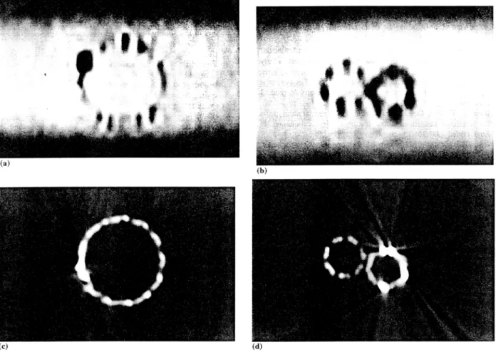
Fig. 2. Coronal 3D M R A source image (a) of the stent graft. The woven wires of the stent-graft are well visualized on the image against the contrast enhanced agar-gel. Platinum markers at the junction of the two stent components (arrow/. Axial CT (b) and M R (c) images through the center of the aortic portion. Reflecting its increased density, the stent is depicted as a bright ring on axial CT images (b). On axial M R images (c) the stent structure created a signal void and was thus displayed as a dark ring.
nounced for M R A than CTA. In fact artifacts emanat-
ing from the platinum markers were considerably less
severe on the MR-images. A wider area of signal loss
was seen only at the insertion of the iliac stent leg into
the aortic stent portion. This most likely reflects the
overlap of two radio-opaque platinum markers. This
artifact should under no circumstance be confused with
a stenosis.
The introduction of metallic conducting materials
into the scanner can potentially lead to hazardous
ferromagnetic and thermal effects [11-13]. The Van-
guard bifurcated stent graft can be imaged without risk
P.R. Hilfiker et al.. ,~htgnetic Resommce Materials in Physics, Bh~h~gy aml Medicine 8 (1999) 2 7 - 3 2 31
of heating or magnetically induced device migration.
Ferromagnetism could be excluded, as well as tempera-
ture increase during 3D G R E imaging [14].
After dispelling artifact- and safety-related concerns,
potential advantages of 3D M R A over CTA regarding
their application to post-stent follow-up imaging may
be considered. Beyond the absence of ionizing radia-
tion, paramagnetic contrast agents are not nephrotoxic
[15,16], permitting their repetitive use even in patients
with impaired renal function. As many of the patients
with aortic aneurysms have concomitant renal insuffi-
ciency [17-19] this aspect is of particular significance.
Other advantages of 3D M R A over CTA, regarding
assessment of the aorta with or without the presence of
an endoluminal stent relate to the ability to image in
the coronal plane. Better in plane resolution on coronal
source images results in improved delineation of the
aorta along its mostly coronal course [5]. Furthermore,
the coronal acquisition plane extends the field-of-view
to 40 cm thereby easily encompassing the pelvic arter-
i e s - a n important aspect regarding both pre-proce-
dural planning of stent delivery and post-stenting
follow-up.
The outlined advantages do indeed suggest the use of
3D M R A for stent-graft follow-up imaging. A number
of possible limitations must, however, be considered.
Thus M R A cannot be performed on patients with
contraindications to MR imaging, such as implanted
pacemakers. Furthermore, the signal void around the
stent-graft may hamper the detection of perigraft chan-
nels in the same way as in CT. This can be compen-
sated for by closely following the size of the aneurysmal
sac [4]. Any enlargement following stenting would indi-
cate failure of the procedure. Finally it is crucial to
point out that the favorable results documented with
the Vanguard bifurcated stent graft cannot be general-
ized to other devices. Both artifact and safety character-
istics are dependent on the composition of the
individual stent graft. In view of considerable similari-
ties between the different models, similarly favorable
results can, however, be expected. These 'in vitro' ex-
periments demonstrate that artifacts associated with the
wall of the stent graft are not more pronounced on 3D
M R A images than on CTA images. Merely those focal
areas containing a platinum marker caused more signal
drop-out on M R A data sets. 3D MRA images should
Fig. 3. MR (a, b) and CT (c, d) images of the stent-graft obtained at identical location traversing the platinum marker at the proximal aortic
portion (a, c) and traversing the platinum marker at the junction of the two stent components in the proximal iliac portion (b, d). The platinum
markers induce a starburst pattern on CT images, whilst the platinum-induced signal voids simulated a widening of the stent wall on MR images.
32 P.R. Hi(fiker et a l . / Magnetic Resonance Materials in Physics, Bioh)gy and Me~ficine 8 (1999) 27-32 Table l
Measurement of the wall thickness and diameters"
CT/mm MRI/mm Stent dimensions/mm
Diameter of prox. Aortic part 21.9 + l.l 21.8 + 0.7 (P = 0.85) 24 Diameter of center of aortic part 21.7 _+ 1.2 21.7 _+ 0.6 (P = 0.93) 24 Diameter prox. iliac portion
Attached iliac section 7.4 + 0.2 7.6 +_ 1.1 (P = 0.83) I0
Inserted iliac section 6.9 + 0.5 5.5 _+ 0.8 (P = 0.02) 10 (junction) Diameter center o f iliac legs
Attached iliac section 7.3 _+ 0.2 7.7 _ 1.0 (P = 0.77) 10 Inserted iliac section 9.2 + 0.6 9.2 + 1.0 (P = 0.96) 12 Diameter distal iliac legs
Attached iliac section 7.3 + 0.3 7.6 _+ 0.9 (P = 0.81) 10 Inserted iliac section 8.8 _+ 0.6 8.5 _+ 0.6 (P = 0.80) 12
Wall thickness 2.3 + 0.4 2.4 _+ 0.8 (P = 0.67) 0.35
Platinum markers 2.0 _+ 0.5 3.4 _+ 1.3 (P = 0.02) 0.95
" The stent-graft had the following sizes: diameter of the aortic part: 24 mm: diameter of the attached iliac section: 10 mm; diameter of the inserted iliac section: 10 mm (junction), 12 mm (free end)
t h u s p e r m i t a c o m p r e h e n s i v e a s s e s s m e n t o f t h e a r t e r i a l l u m e n a s w e l l a s o f p e r i v a s c u l a r t i s s u e s , t h e r e b y e v o l v - i n g i n t o a n a l t e r n a t i v e f o r t h e f o l l o w - u p o f s t e n t - g r a f t - i n g p r o c e d u r e s .
R e f e r e n c e s
[1] Parodi JC, Marin ML, Veith FJ. Transfemoral, endovascutar stented graft repair of an abdominal aortic aneurysm. Arch Surg 1995;130:549:52.
[2] Parodi JC, Barone A, Piraino R, Schonholz C. Endovascular treatment of abdominal aortic aneurysms: lessons learned. J Endovasc Surg i997;4:102-10.
[3] Blum U, Voshage G, Lammer J, et al. Endoluminal stent-grafts for infrarenal abdominal aortic aneurysms [see comments]. N Engl J Med 1997;336:13-20.
[4] Rozenblit A, Marin ML, Veith F J, Cynamon J, Wahl SI. Bakal CW. Endovascular repair of abdominal aortic aneurysm: value of postoperative follow-up with helical CT. Am J Roentgenol 1995;165:1473-9.
[5] Thurnher SA, Dorffner R, Thurnher MM, et al. Evaluation of abdominal aortic aneurysm for stent-graft placement: compari- son of gadolinium-enhanced MR angiography versus helical CT angiography and digital subtraction angiography. Radiology
1997;205:341-52.
[6] Cragg AH, De Jong SC, Barnhart WH, Landas SK, Smith TP. Nitinol intravascular stent: results of preclinical evaluation. Ra- diology 1993;189:775-8.
[7] Blum U, Langer M, Spillner G, et al. Abdominal aortic aneu- rysms: preliminary technical and clinical results with trans- femoral placement of endovascular self-expanding stent-grafts [see comments]. Radiology 1996:198:25-31.
[8] Teitelbaum GP, Bradley WG Jr, Klein BD. MR imaging arti- facts, ferromagnetism, and magnetic torque of intravascular filters, stems, and coils. Radiology 1988;166:657-64.
[9] Teitelbaum GP, Raney M, Carviin M J, Matsumoto AH, Barth KH. Evaluation of ferromagnetism and magnetic resonance
imaging artifacts of the Strecker tantalum vascular stent. Cardio- vasc Iotervent Radiol 1989;12:125-7.
[10] New PFI, Rosen BR, Brady TJ, et al. Potential hazards and artifacts of ferromagnetic and nonferromagnetic surgical and dental materials and devices in nuclear magnetic resonance imag- ing. Radiology 1983;147:139-48.
[1.1] Maier SE, Wildermuth SE, Darrow RD, Watkins RD, Debatin JF, Dumoulin CL. Safety of M R Tracking catheters. Proceed- ings of the Society of Magnetic Resonance, 3rd Scientific Meet- ing, Nice, 1995. p. 497.
[12] Ladd ME, Quick HH, Debatin JF, von Schulthess GK, Mc Kinnon GC. Safety of actively visualized vascular guidewires-- Localized heating, t4th annual meeting European Society for Magnetic Resonance in Medicine and Biology. Book of ab- stracts, Brussels. 1997, p. 281.
[13] Quick HH, Ladd ME, von Schulthess GK, Debatin JF, Heating effects of an intravascular catheter. 14th annual meeting Eu- ropean Society for Magnetic Resonance in Medicine and Biol- ogy. Book of abstracts, Brussels, 1997, p. 563.
[14] Hilfiker PR, Pfammatter T, Hany TF, Lachat M, Debatin JF, 3D MRA in patients with abdominal aortic aneurysm post stent-grafting. 6th scientific meeting ISMRM. Book of abstracts, Sydney, 1998, p. 175.
[15] Niendorf HP, Hauenstein J, Cornelius I, Alhassan A, Clauss W. Safety of gadolinium-DTPA: extended clinical experience. Magn Reson Med 1991;22:222-8.
[16] Nelson KL, Gifford LM, Lauber-Huer C, Gross CA, lesser TA. Clinical safety of gadopentetate dimeglumine. Radiology 1995;196:439-43.
[17] Koskas F, Kieffer E. Long-term survival after elective repair of infrarenal abdominal aortic aneurysm: results of a prospective multicentric study. Association for Academic Research in Vascu- lar Surgery (AURC). Ann Vasc Surg 1997;11:473-81.
[18] Muluk SC, Painter L, Sile S, et al. Utility of clinical pathway and prospective case management to achieve cost and hospital stay reduction for aortic aneurysm surgery at a tertiary care hospital. J Vasc Surg 1997;25:84-93.
[19] Komori K, Kuma S, Eguchi D, et al. Surgical strategy of abdominal aortic aneurysm with preoperative renal failure. Eur J Vasc Endovasc Surg 1997;14:105-8.