HAL Id: hal-00547113
https://hal.archives-ouvertes.fr/hal-00547113
Submitted on 15 Dec 2010
HAL is a multi-disciplinary open access
archive for the deposit and dissemination of
sci-entific research documents, whether they are
pub-lished or not. The documents may come from
teaching and research institutions in France or
abroad, or from public or private research centers.
L’archive ouverte pluridisciplinaire HAL, est
destinée au dépôt et à la diffusion de documents
scientifiques de niveau recherche, publiés ou non,
émanant des établissements d’enseignement et de
recherche français ou étrangers, des laboratoires
publics ou privés.
Fast Environment Extraction for Lighting and Occlusion
of Virtual Objects in Real Scenes.
François Fouquet, Jean-Philippe Farrugia, Brice Michoud, Sylvain Brandel
To cite this version:
François Fouquet, Jean-Philippe Farrugia, Brice Michoud, Sylvain Brandel. Fast Environment
Extrac-tion for Lighting and Occlusion of Virtual Objects in Real Scenes.. IEEE InternaExtrac-tional Workshop on
Multimedia Signal Processing, Oct 2010, Saint Malo, France. pp.actes electroniques. �hal-00547113�
Fast Environment Extraction for Lighting and
Occlusion of Virtual Objects in Real Scenes
Franc¸ois Fouquet
#1, Jean-Philippe Farrugia
#2, Brice Michoud
#3, Sylvain Brandel
#4# Universit´e de Lyon, CNRS
Universit´e Lyon 1, LIRIS, UMR5205, F-69622, France
1[email protected] 2[email protected]
3[email protected] 4[email protected]
Abstract—Augmented reality aims to insert virtual objects in real scenes. In order to obtain a coherent and realistic integration, these objects have to be relighted according to their positions and real light conditions. They also have to deal with occlusion by nearest parts of the real scene. To achieve this, we have to extract photometry and geometry from the real scene. In this paper, we adapt high dynamic range reconstruction and depth estimation methods to deal with real-time constraint and consumer devices. We present their limitations along with significant parameters influencing computing time and image quality. We tune these parameters to accelerate computation and evaluate their impact on the resulting quality. To fit with the augmented reality context, we propose a real-time extraction of these information from video streams, in a single pass.
I. INTRODUCTION
Augmented reality is a set of techniques used to integrate virtual and real elements into a coherent scene. The user can usually move freely in a real environment augmented with synthetic objects. Applications of this technology are numerous, ranging from video games to personal training in hazardous environments like nuclear power plants for example. Traditionally, augmented reality needs specialized hardware, like see-through glasses, often with specially equipped rooms. In our project, the objective is to open this technology to a broader audience. Therefore, we chose to only use widely adopted consumer products (webcams, graphics processing units, video-projectors...).
Augmenting reality also means synchronizing two represen-tations: the real environment and the virtual scene we want to insert. Depending on the targeted application, this fusion necessitates more or less precise or complete computations. For instance, a copy machine repair assistance needs precise localization of virtual indications (ie. aligned with the ma-chine’s mechanical parts). But re-lighting and shading these elements is not critical for application viability. In the opposite, a re-construction of a destroyed historical heritage needs to be convincing to one’s perception. In this case, registration may be less precise without disturbing the user, but incorrect occlusions and lighting affect visual realism.
MMSP’10, October 4-6, 2010, Saint-Malo, France. 978-1-4244-8112-5/10/$26.00 2010 IEEEc
In our study, we were interested in this second case. Therefore, to achieve a realistic augmented reality, we need to acquire several types of environment information. For now, our work focuses on geometry and light, since both are needed for virtual objects incrustation and basic re-lighting. A great number of methods have been proposed to acquire these information from single and multiple points of view, but very few of them have been adapted to real-time processing with consumer hardware.
In this paper, we propose to select one method for photo-metric acquisition and one for geometry acquisition, and to test influence of various input parameters on computation time. We propose to use the same input data for simultaneously applying both techniques on a unique process. The final objective is to obtain a good compromise between computation and quality, in order to apply these methods in an augmented reality process.
This article is divided into three sections. The next section presents previous works, and methods we developed to fast acquire photometry from images sets and video streams. The following section is similar with geometry acquisition. The next section describes a sample of application joining both acquisition fields. Finally, the last section concludes with important results, perspectives and future works.
II. PHOTOMETRY ACQUISITION
A. Previous work
Since standard cameras are unable to give images containing the whole dynamic of a scene, we use HDR (High Dynamic Range) images [1] which allows to store real radiance values for each pixel. These images therefore need a tone mapping transformation to be displayed on a screen. Techniques to recover HDR images combine multiple images from the same viewpoint with different exposures [2] [3] or different shutter times [4] [5].
B. HDR image construction
In our augmented reality approach, the input is a video stream, with possible shutter time variations, so we chose De-bevec and Malik method [4]. This technique uses images taken from the same point of view and with different shutter times.
First, it introduces a method for camera response function determination, and then proposes a way of combining input images with this function. It is finally possible to determine all radiance levels contained in the image set. images taken with a short shutter time (ex: 1/1000) contain information on high energy areas of the scene, while long shutter time images give information on low energy areas. For the camera response determination, authors manually select points on images, then search the response function that best matches them. An approximating function is estimated by solving an over-determined equation system, built with radiance values on each selected point and its corresponding shutter time. For HDR image construction, authors apply the inverse of response function to all input images. Final image is obtained by computing the weighted average of transformed images.
For each pixel i of a picture with a shutter time Tj, the radiance value Zij is computed from energy Ei obtained by the sensor and transformed by response function f specific to the sensor: Zij = f (EiTj). To build HDR picture, we compute Ei to pixel i:
Ei = f −1(Zij)
Tj
(1)
We have to compute simultaneously the response function f and Ei to each point of the picture. To build HDR picture, we first compute napierian logarithm g of the inverse function of f . g is a discrete function defined on interval [0-255], so we have to compute values from g(0) to g(255) to totally compute g:
g(Zij) = ln(f−1(Zij)) = ln(Ei) + ln(Tj) (2) Function g is specific to a sensor. So we search g(Zij) such as equation (2) is verified for all points of all input pictures. We obtain a system with P ×Nt equations, P is the number of input pictures, Nt the number of pixels on each picture:
Nt X i=1 P X j=1 [g(Zij) − ln(Ei) − ln(Tj)] = 0 (3)
To solve this over-determined system, Debevec and Malik proposed to manually pick some pixels, and to force g to be continuous and monotonous by fixing g00(z) = g(z − 1) − 2g(z) + g(z + 1) = 0 with z belonging to [1-254]. Moreover, they add a ponderation function w(z) to decrease the impact of z near extrema of radiance values. So w(z) = z for z ∈ [0 − 127] and w(z) = 256 − z for z ∈ [128 − 255]. Finally, we have to minimize the following system, N is the number of picked pixels, z are the radiance values of input pictures (grayscale beetween Zmin = 0 and Zmax= 255):
θ = N X i=1 P X j=1
{w(Zij)[g(Zij) − ln(Ei) − ln(Tj)]}2
+
Zmax−1
X z=Zmin+1
[w(z)g00(z)]2 (4)
Using g, we can now compute radiance picture for each pixel:
ln(Ei) = PP j=1w(Zij)[g(Zij) − ln(Tj)] PP j=1w(Zij) (5)
With our implementation (Quadcore 2.5GHz with RAM 2GB), this method constructs an HDR image (640×480) in 4 seconds, starting from a sequence of 12 pictures of a video stream with shutter time varying from 1/1024s. to 2s. We added an automatic point selection, based on similar energy areas through different images. Since our study evaluates exist-ing methods to adapt them to augmented reality, we focused on identifying their limitations. Therefore, we searched for parameters accelerating the computation in order to reach real-time with minimal quality loss.
C. Reduction of computation time
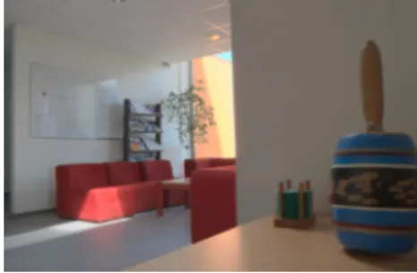
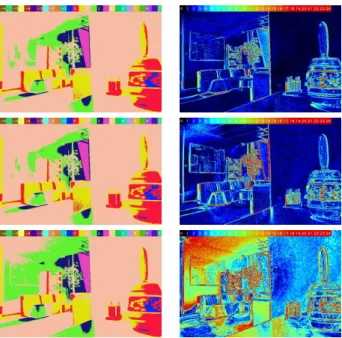
In order to reduce computing time, we consider that the camera response function is constant. Therefore, it may be estimated once for all in a pre-computing phase. Then, we noticed that the number of input images is directly related with the computation time. Thus we proposed a test to evaluate the influence of this parameter on HDR images. In a first step, the camera response function is pre-computed on the whole image set (12 images). Then we perform HDR construction from 2, 4 and 6 input images. We also compute a reference radiance map from the 12 input images (figure 1). We display these results with a color range visualization tool in which each color correspond to an half order of radiances. This tool allows a quick evaluation of radiance map coherence with the observed environment. We also proposed a second tool which compares each HDR image with the reference one. It returns an image in which each pixel color corresponds to the relative percentage difference between current image and reference image. Results, on figure 2, show that radiance maps are coherent whatever the number of input images. It also shows that differences are low when using more than 2 input images.
Fig. 1. Tone mapping of HDR reference image.
The reduction of input images involves to carefully select their shutter times. This choice has no influence on computing time but has an important impact on HDR image quality and acquisition time. A new test, similar to the previous one but not displayed here for space considerations, showed that choosing shutter times equally distributed on the available
Fig. 2. Influence of the input image number. Left: Color range visualizations. Right: Comparisons with reference. Upper line: 6 images. Middle line: 4 images. Lower line: 2 images. Comparison scale: from black for pixels having the same value on image and reference to red for pixels having 25% or more difference.
range offers good results. We can also notice that this range is not interesting in its whole for augmented reality. Indeed, to relight virtual objects we need to know information on environment light sources only. A light source is supposed to have a high radiance and therefore to be observed on short shutter time images. It is then possible to remove long shutter time images, which are obviously very long to acquire. This test also pointed out that the observed loss of quality in HDR reconstruction is quite predictable: errors systematically appeared in the area where the well-exposed image has been removed.
III. GEOMETRY ACQUISITION
A. Previous works
There is a great number of methods allowing to retrieve geometry from images. Geometry can be described in a global coordinate system, using shape from silhouette methods based on visual hull [6], or stereo-vision techniques [7]. These techniques need several calibrated cameras, quite difficult on unknown environments. Geometry can also be described with a depth map giving the distances between objects and the user’s viewpoint, using single image from a single viewpoint. Depth map can be computed using dedicated hardware [8] [9] or under control lighting like shape from shading [10] [11]. A recent method [12] uses automatic learning on images database. Others techniques compute depth from focus length of standard devices, like depth from defocus [13] [14] or depth from focus [15] [16].
B. Depth map construction
Since we use camera with focus length variation in our augmented reality environment, we chose a depth from focus
method. All images are taken from the same viewpoint, but with different focus parameters. Then, we apply on each pixel of these images an estimator of focus which returns a value representing the blur level. The chosen estimator is based on laplacian operator computing the variation of intensity on edges. The higher this operator is on a given edge, the better the camera is focussed on it. We then compute a single image registering for each pixel the focus parameter of the best focussed image. Finally, this image is converted into depth map using a look up table (LUT) pre-computed during a calibration step. This calibration is performed by shooting a chessboard pattern positioned at a known distance using all focus values available in our camera. Assuming that all points contained in the chessboard plan are at the same distance from the camera, we compute the sum of local laplacian operator on each image. Then, we search the maximum of this sum according to the focus value. The corresponding focus parameter is associated with the chessboard distance in the LUT. This process is iterated with other distances until having a complete LUT between focus parameters and distances.
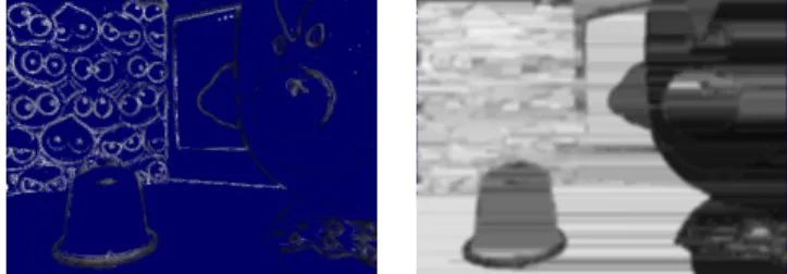
To compute depth maps, we first acquire an image set containing images with different focus values. Then, we apply the focus estimation on each pixel of each image and we just retain the focus value corresponding to the best focused image (the image where the estimator is maximum). However, this method computes focus estimation on every pixel in image, even pixels located in a non-textured area. In this case, the edge information used to evaluate the focusing is missing and the estimator returns very low values. The retained value is then the one corresponding to the maximum of noise. For this reason, we decided to add a threshold to filter estimator values and remove unreliable points. Finally, the depth map is reconstructed by replacing the focus value with the corresponding distance in the LUT. Figure 3 shows an example of depth map computed from 256 images in 9 seconds.
Fig. 3. Left: Example of image from the input set (640×480). Right: Depth map coresponding to the same resolution. The color scale is linearly varying from black (2cm and less) to white (60cm and more). Green pixels correspond to the points that are rejected by thresholding.
The depth map we currently construct has only information on edges that are not enough for proper occlusion handling, so we developed methods returning dense depth maps to correctly manage occlusions. The more convincing method works on two passes. First pass horizontally (resp. vertically) fills missing data betweens valued edges. All non valued pixels between a picture boundary and an edge are filled with
highest (farthest) value. All non valued pixels between two valued edges are filled with the highest (farthest) value of both edges values. We don’t perform a linear interpolation to avoid the creation of artifacts between background and foreground objects. Second pass is a simple average of horizontal and vertical filled picture. Figure 4 shows an example of filling depth map.
Fig. 4. Filling of depth map. Left: sparse depth map. Right: resulting dense depth map.
Better dense depth maps can be built by taking into ac-count smoothness constraints between neighboring pixels and performing a global optimization of the depth map, but these methods are traditionally slower and thus might not seem to be useful in our application. Notice that real-time methods exist, using GPU and stereo devices for belief propagation for the computation of dense depth maps in real-time [17]. The belief propagation module could take the values which are obtained by the Laplace operator applied to a defocused image as an input.
C. Reduction of computation time
A first way to reduce computation time is reducing image number. We noticed during the calibration step that, because of hardware limitations, images which have a focus parameter at extremities of the focus range do not contain useful infor-mation for depth recovering. So we may reduce the input data volume by removing these extreme images and by regularly excluding images from the input set. To evaluate consequences of image number reduction, we made some other tests with 3 input image subsets. The first one is built by selecting 1 image on 10 in the initial data set. The second keeps 1 image on 20 and the third 1 on 40. Computation time on 640×480 is 1.5s for 20 images, 0.8s for 10 images and 0.5s for 5 images. Reconstructed depth maps are visually coherent whatever the number of input images. Therefore, reducing the volume of input images seems to be an interesting method to save computation time in order to be used in augmented reality. It is important to see that removing images from the input set directly influence the accuracy of resulting depth maps because the construction method obviously gives a number of depth plans equal to the number of input images (respectively 20, 10 and 5 in our case). Notice that the performed selection does not correspond to a regular discretization of depth space: the LUT gives a non-linear correspondence between focus parameters and distances. It is however enough to reconstruct depth maps and evaluate their coherence.
These results show that the reduction of input images number implies a proportional reduction of computation time. Reconstructed depth maps are visually coherent whatever the number of input images. Therefore, reducing the volume of input images seems to be a interesting method to save computation time in order to be used in augmented reality.
An other way to reduce computation times consists in reducing the size of input images and evaluating consequences on depth maps. Indeed, as for radiance recovering, we suppose that the depth information does not have to be very spatially accurate for synthetic object inclusion in a real scene. We also perform a new test of computation speed using sets of 256 resized images. We used two sets of images which size are respectively 320×240 and 160×120. Depth map is computed from the first set in 4.1 seconds, from the second set in 1.1 second (figure 5). Resizing images to 320×240 preserves the global coherence but a 160×120 resizing produces errors which are visually important. It is currently better to avoid the use of to small images, but this may be revised in case of implementing other focusing estimator.
Fig. 5. Reduction of image size. Left: 320×240. Right: 160×120.
As in the previous test, we observed significant computation time reduction, which is very interesting for augmented reality. However, we observe that resizing images to 320×240 pre-serves the global coherence but a 160×120 resizing produces errors which are visually important. It is currently better to avoid the use of to small images, but this may be revised in case of implementing other focusing estimator.
To conclude this study, we want to present an other test combining both types of reduction (figure 6). We perform the computation of a depth map using a selection of 5 input images resized to 320×240, computation time is 170ms. This is an encouraging result because we can construct 6 depth maps per second with 5 input images for each. It corresponds to the input data acquisition limit which is 30 FPS for an ordinary webcam.
IV. RESULTS
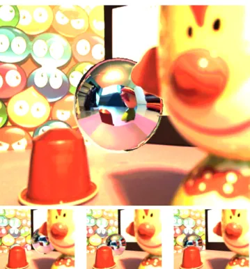
To put our method to the test, we show an example appli-cation (figures 8, 9 and 10) by inserting a virtual object into a real scene using a single capture with an ordinary webcam. We acquire six HDR images from the middle of the scene, on six basis directions (front, back, left, right, up and down), by simples hand manipulations of the webcam. These pictures are thus converted on a HDR cubemap during a pre-procesing step (figure 7). Than we capture a depth map and HDR images from the point of view.
Fig. 6. Example of combining image size and number of image reductions.
Fig. 7. Cubemap built with 6 HDR pictures (top view) and reflection on a sphere (front view).
The rendering process is then decomposed in two passes. During the first one, we use a very simple relighting technique by lighting a specular virtual object using the HDR cubemap and storing the resulting image into a texture. During the second pass, we add the previous pass with the HDR image. We handle occlusions between real and virtual objects by comparing virtual depth computed in the previous pass with the value stored in the depth map. Environment acquisition (HDR + depth) is done in a few seconds, using 9 images for each HDR image and 9 for the depth map. It is not real-time, but a fast out-of-core pre-computation, in which variations of focus and shutter time during acquisition do not affect final rendering. Scene rendering is real-time. Although changing the point of view is not possible after acquisition step, moving the virtual object with dynamic lighting and occlusion computation is performed in real-time.
Fig. 8. Rendering of a virtual object (bigguy) in a real scene.
V. SUMMARY,CONCLUSION AND PERSPECTIVES
This study has pointed out that multiple methods of depth and light acquisition exist. We have also seen that most of
Fig. 9. Rendering of a virtual object (sphere) in a real scene.
Fig. 10. Rendering of a virtual object (bunny) in a real scene.
them presented difficulties for augmented reality applications because they require much computation or represent data in an incompatible way. Then, we have selected some methods that we considered well adapted and we have explained experiments we performed on to evaluate their capacity to be used in augmented reality. These tests have shown that HDR acquisition and depth map acquisition would both be possible in interactive time with consumer hardware.
This work also opens number of perspectives in environment acquisition, like GPU and multi-core CPU programming. We also foresee to improve the rendering in augmented reality, by acquiring other data on environment, such as surface aspect of objects. Thus, we would be able to consider more complex optical phenomena to increase rendering realism. For instance, recovered data are currently not enough to determine if there is a mirror-like surface in the scene. So we can not compute any reflection of synthetic object on the environment, which produces a important lack of realism. Moreover, to relight an object, we have to know the lighting at its insertion point. In our future work, we will necessary have to develop and use methods evaluating the lighting in any point of a scene
from the known information. On the other hand, working on augmented reality present some advantages too because it allows to access further information (user’s location in environment, camera gaze direction, multiple and close views of a same scene) on which we plan to develop more efficient and robust acquisition methods.
ACKNOWLEDGMENTS
This work was supported by the French National Research Agency, bearing the reference ANR-07-MDCO-001. It re-ceived the support of Rhˆone-Alpes’s French region project LIMA managed by the ISLE cluster.
REFERENCES
[1] E. Reinhard, G. Ward, S. Pattanaik, and P. Debevec, High Dynamic Range Imaging: Acquisition, Display, and Image-Based Lighting. Mor-gan Kaufmann Publishers Inc., 2005.
[2] B. Madden, “Extended intensity range image,” University of Pennsyl-vania, Tech. Rep., 1993.
[3] S. Mann and R. W. Picard, “Extending dynamic range by combining different exposed pictures,” in Proceedings of the 48th Annual Confer-ence of The Society for Imaging SciConfer-ence and Technology (IS&T), 1995, pp. 442–448.
[4] P. E. Debevec and J. Malik, “Recovering high dynamic range radiance maps from photographs,” in Proceedings of the 24th annual conference on Computer graphics and interactive techniques (SIGGRAPH ’97), 1997, pp. 369–378.
[5] T. Mitsunaga and S. Nayar, “Radiometric Self Calibration,” in Pro-ceedings of the IEEE Conference on Computer Vision and Pattern Recognition (CVPR ’99), vol. 1, 1999, pp. 374–380.
[6] A. Laurentini, “The visual hull concept for silhouette-based image understanding,” IEEE Transactions on Pattern Analysis and Machine Intelligence, vol. 16, no. 2, pp. 150–162, 1994.
[7] O. Faugeras, Three-Dimensional Computer Vision: A Geometric View-point. MIT Press, 1993.
[8] A. Levin, R. Fergus, F. Durand, and W. T. Freeman, “Image and depth from a conventional camera with a coded aperture,” in Proceedings of the 34th annual conference on Computer graphics and interactive techniques (SIGGRAPH ’07), 2007, pp. 70–78.
[9] R. Gvili, A. Kaplan, E. Ofek, and G. Yahav, “Depth keying,” in Proceedings of SPIE Electronic Imaging Conference, vol. 5006, 2003, pp. 564–574.
[10] R. Zhang, P. Tsai, J. Cryer, and M. Shah, “Shape from shading: A sur-vey,” IEEE Transactions on Pattern Analysis and Machine Intelligence, vol. 21, no. 8, pp. 690–706, 1999.
[11] A. Meyer, H. B. Pulido, and S. Bouakaz, “User-guided shape from shad-ing to reconstruct fine details from a sshad-ingle photograph,” in ACCV’2007 : 8th Asian Conference on Computer Vision, Oct. 2007.
[12] A. Saxena, S. Chung, and A. Ng, “3-d depth reconstruction from a single still image,” International Journal of Computer Vision, vol. 76, no. 1, pp. 53–69, 2008.
[13] A. P. Pentland, “A new sense for depth of field,” IEEE Transactions on Pattern Analysis and Machine Intelligence, vol. 9, no. 4, pp. 523–531, 1987.
[14] Y. Xiong and S. Shafer, “Depth from focusing and defocusing,” in Proceedings of the IEEE Conference on Computer Vision and Pattern Recognition (CVPR ’93), 1993, pp. 68–73.
[15] P. Grossmann, “Depth from focus,” Pattern Recognition Letters, vol. 5, no. 1, pp. 63–69, 1987.
[16] S. Nayar and Y. Nakagawa, “Shape from Focus,” The Robotics Institute, Carnegie Mellon University, Tech. Rep., 1989.
[17] Q. Yang, L. Wang, R. Yang, S. Wang, M. Liao, and D. Nister, “Real-time global stereo matching using hierarchical belief propagation,” in The British Machine Vision Conference (BMVC), 2006.