Broadband Active Structural Control Using
Collocated Piezoelectric Sensors and Actuators
by
Cagri Abdullah Savran B.S. Mechanical Engineering
Purdue University, 1998
SUBMITTED TO THE DEPARTMENT OF MECHANICAL ENGINEERING IN PARTIAL FULFILLMENT OF THE REQUIREMENTS FOR THE DEGREE OF
MASTER OF SCIENCE IN MECHANICAL ENGINEERING AT THE
MASSACHUSETTS INSTITUTE OF TECHNOLOGY JUNE 2000
©
2000 Massachusetts Institute of Technology. All Rights Reserved. Signature of Author ...Department of Mechanical Engineering May 5, 2000
Certified by ...
Steven R. Hall Associate Professor of Aeronautics and Astronautics Thesis Supervisor
Certified by ...
/7r
Kamal Youcef-Toumi/Professor of Mechanical Engineering Departmental Reader
A ccepted by ...
Ain A. Sonin
Chairman, Department Committee on Graduate Students Department echanical Engineering
MASSACHUSETTS OFTECHNOLOGYIkS-TITUTE
Broadband Active Structural Control
Using Collocated Piezoelectric Sensors and Actuators
by
Cagri Abdullah Savran
Submitted to the Department of Mechanical Engineering on May 5, 2000, in partial fulfillment of the requirements for the degree of
Master of Science in Mechanical Engineering
Abstract
This thesis presents active structural control experiments performed on a model fuselage testbed, to reduce interior noise. The testbed is a hybrid-scaled model fuselage designed to be representative of complex aircraft structures with rib and stringer construction, which results in a structure with high modal density and complex behavior. Collocated pairs of piezoelectric sensors and actuators were used to achieve robust stability. The sensor/actua-tors pairs consist of PVDF film and PZT ceramic sheets bonded to the surface of the model fuselage.
Closed-loop control of the fuselage skin was carried out with 30 collocated sensor/actua-tor pairs, covering approximately 10% of the surface area of the testbed. The disturbance source was a PZT patch bonded to an adjacent panel. Rate feedback was applied to each collocated pair separately but simultaneously (independent loop closure). Accelerometers attached to the panels and microphones located inside the testbed were used as perfor-mance sensors. The experimental results show as much as 20 dB reduction in structural acceleration and up to 10 dB attenuation in interior acoustic pressure level, at resonant peaks, over a frequency range of 100-2000 Hz.
Thesis Supervisor: Steven R. Hall
Acknowledgements
This research was supported by an Army Research Office Multidisciplinary University Research Initiative (MURI) grant, under the program MURI DAAH 4-95-1-0104, with technical monitor Dr. Gary Anderson.
Special thanks go to my undergraduate colleague Daniel Kwon without whose help, the instrumentation for this research would not be done in a timely manner. I would also like to thank the undergraduate research assistants Christian Garcia and Eric Coulter for the help they provided for the experimental setup. Very special thanks go to Paul Bauer and Dave Robertson without whose help the instrumentation would never be completed. I would like to acknowledge the assistance on thermoplastic adhesives provided by Ken Thompson of 3M Innovation. My profound thanks go to Mauro Atalla, Michael Fripp and Kyung-yeol Song for all the help they provided for my research. I would like to thank my research advisor Steven Hall for his guidance and invaluable insight. I would also like to thank my 16.243 instructor Ed Crawley for telling me that I was a "very lucky boy" for achieving performance with a transfer function that doesn't roll off. Hale, and Fatih deserve most special thanks for encouraging and supporting me in difficult times. I would like to thank my family members who have always been supportive, considerate, and patient.
Finally, I would like to commemorate and dedicate this thesis to my elementary school teacher Ismail Hakki Kandemir who taught me how to think and be open-minded.
Table of Contents
Acknowledgements ... Table of Contents ... List of Figures ... Chapter 1. Introduction ... . . . .1 1 Motivation ... Background ... Approach ... Overview ...Chapter 2. Experimental Setup ... 2.1 Testbed...
2.2 Sensor and Actuator Sel 2.2.1 Actuator Selectio 2.2.2 Sensor Selection 2.2.3 Sensor and Actu 2.3 The Active Ply ...
2.3.1 Manufacturing a
...
ection ...
n ... .. . . . .. . . . .
ator Placement ... nd Bonding the Active Ply 2.4 Finalized setup ...
2.5 Sum m ary ...
Chapter 3. Control System Design ...
3.1 An Overview of Structural Control Architectures .... 3.2 Local Control Methods ...
3.3 System Identification ...
3.3.1 Disturbance to Performance Transfer Functions 3.3.2 Actuator to Sensor Transfer Functions ... 3.4 Control Law ...
3.5 Sum m ary ...
Chapter 4. Control Implementation and Experimental Results 4.1 Control Implementation ... 4.1.1 Digital Approach ... 4.1.2 Analog Approach ... 4.2 Experimental Results ... 4.3 Sum m ary ... . . . ..5 . . . ... 7 1.1 1.2 1.3 1.4 . . . 9 11 12 15 16 . .... ... 17 17 21 21 23 30 35 37 40 42 ... 43 43 47 53 54 56 58 70 .73 .74 .74 .78 .80 .89
Chapter 5. Conclusions ... 91
5.1 Sum m ary ... 91
5.2 Conclusions ... 94
5.3 Recommendations for Future Work ... 96
Appendix A Equipment Specifications and Manufacturer Information ... 99
List of Figures
2.1 2.2 2.3 2.4 2.5 2.6Testbed in anechoic chamber and its CAD drawing... PZT to accelerometer transfer function... The curved panel and the schematic of the collocated PVDF-PZT pair. . PZT to PVDF transfer function on the curved panel... PZT-Copper kapton-PVDF patch...
PZT to PVDF transfer function of the PZT-Copper kapton-PVDF patch. 2.7 PZT-PVDF transfer function of the fuselage testbed . ...
2.8 Single panel sensor/actuator placement . ... 2.9 5 PZT-Copper kapton-PVDF patches on a testbed panel ... 2.10 PZT to PVDF transfer function for the central patch of the panel. 2.11 PZT to PVDF transfer functions from 5 patches ...
2.12 An exploded view of the active ply... 2.13 Hot and ground electrode patterns . ...
2.14 A finalized active ply . ...
2.15 Testbed with six active plies... 2.16 Schematic of the instrumented area of the testbed... 3.1 Mode shape of the testbed at 674 Hz . ...
3.2 Root locus of an arbitrary 3 degree-of-freedom flexible plant with collocated sensors and actuators when controlled by PPF with a pair of complex poles... 3.3 Root locus of an arbitrary 3 degree-of-freedom flexible plant
with collocated sensors and actuators when controlled by PPF with a single real pole...
3.4 Root locus of an arbitrary 3 degree-of-freedom flexible plant
... 18 ... 25 ... 26 ... 27 ... 28 ... 29 ... 30 ... 32 ... 33 ... 33 ... 34 ... 36 ... 37 ... 39 ... 40 ... 41 ... 46 ... 49 ... 50
with collocated sensors and actuators when controlled by rate feedback. . 3.5 Schematic of the control problem... 3.6 Disturbance to accelerometer open-loop transfer function for Panel 1, Location 1... 3.7 Disturbance to microphone open-loop transfer function: The microphone is located behind Panel 2... 3.8 PZT to PVDF transfer function for the central patch of Panel 1... 3.9 Magnitude of transfer functions for all 5 sensor/actuator pairs of Panel 1. 3.10 Force to velocity dereverberated transfer function. ... 3.11 Loop transfer function of a pure rate feedback controller 3.12 3.13 3.14 3.15 3.16 3.17 and a PZT-PVDF pair . ... K(s) where w, = 900 Hz, ( = 0.05, and k = 80... K(s) x GYU(s) where w, = 900 Hz, ( = 0.05, and k = 80 . ... Root locus demonstration of the control system sensitivity to corner frequency in the roll off term of K(s) ... Controller transfer function for various values of ... K(s) where (, = 3100 Hz, ( = 0.18 and k = 108 ... K(s) x GYU(s) for the sensor/actuator pair at Panel 1-Location 1; where wn =3100 Hz, (=0.18 and k = 108... ... 52 ... 54 ... 55 ... 55 ... 57 ... 57 ... 59 ... 60 ... 62 ... 62 ... 64 ... 66 ... 68 ... 68 . . . . . .
3.18 Magnitude of K(s) x GYU(s) for all pairs of Panel 1... 4.1 Basic digital control system with computer ...
4.2 The chosen controller with and without the additional phase lag (Sampling frequency was assumed to be 4100 Hz) . ... 4.3 Analog controller ...
4.4 Open-loop and closed-loop strain autospectra for Panel 1, Location
4.5 Open-loop and closed-loop acceleration autospectra for Panel 1, Location 4...
4.6 Open-loop and closed-loop acceleration autospectra for Panel 2, Location 1...
4.7 Open-loop and closed-loop acceleration autospectra for Panel 3, Location 3...
4.8 Open-loop and closed-loop acceleration autospectra for Panel 4, Location 2 . ... 4.9 Open-loop and closed-loop acceleration autospectra
for Panel 5, Location 1 . ... 4.10 Open-loop and closed-loop acceleration autospectra
for Panel 6, Location 5 . ...
4.11 Open-loop and closed-loop average acceleration autospectra integrated in 100 Hz frequency bands... 4.12 Open-loop and closed-loop acoustic pressure autospectra
for a microphone located behind Panel 2 (#19). ... 4.13 Open-loop and closed-loop acoustic pressure autospectra
for a microphone located behind Panel 2 (#21)... 4.14 Open-loop and closed-loop acoustic pressure autospectra
for a microphone located behind Panel 2 (#23). ... 4.15 Open-loop and closed-loop average acoustic pressure autospectra
integrated in 100 Hz frequency bands...
... 69 ... 74 ... 77 ... 78 1 ... 81 ... 8 1 83 .... 83 .84 ... 84 ... 86 ... 86 ... 88 ... 88 ... 89 R82 . . . .
Chapter 1
Introduction
1.1 Motivation
Excessive interior noise can be a serious problem in aircraft, especially in helicopters. In a commercial helicopter, sound pressure level can reach 95 dB and in a military heli-copter, it can exceed 115 dB [Moreland, 1979]. Several reasons exist for these high sound levels. Firstly, helicopters have stiff but light frames to comply with structural require-ments. This results in a structure that is composed of thin and lightly damped members. A structure with such members tends to be resonant and transmits sound very easily. Sec-ondly, a helicopter cabin typically undergoes various disturbances from the rotor, trans-mission, engine, and boundary layer, which result in broadband structural vibration [Niesl, 1994]. Due to structural coupling, the disturbance caused by each source induces vibra-tions throughout the entire fuselage. Further, structural modes are strongly coupled with many of the acoustic modes of the aircraft interior. This causes noise throughout the cabin. Alleviating this problem may reduce time and cost for maintenance, prevent hearing loss, and improve pilot effectiveness [Leatherwood, 1979] and passenger comfort in general.
A typical helicopter crew member commonly monitors two or three radios. Back-ground noise makes this a very demanding aural task. Besides, effective helicopter opera-tion often depends on a close liaison between crew members and hence on the quality of communication. When manoeuvring to pick up an underslung load or carrying out a res-cue operation, the pilot often relies on the messages received from crewmen. While air crew may be able to cope with noisy environment, it is increasingly difficult if others such
as doctors join the intercom for briefing or discussion. For military situations, troops may require direct-voice re-briefing in flight which is made very difficult by high background noise since intercom outlets are limited [Maitland, 1979].
Other than these immediate effects, repetitive and long lasting exposure to high noise levels also has long-term effects. It is possible for a helicopter crew to be exposed to high noise levels for six or eight hours a day. This results in noise-induced fatigue that can limit prolonged helicopter operation and can also result in permanent aural damage.
1.2 Background
One commonly used approach to address the interior noise problem is passive damp-ing. A variety of insulating materials can be mounted on the structure to reduce its reso-nant behavior by adding damping. Certain foams, polymers, honeycomb structures and multi-layer trim panels can serve as damping materials. Passive damping is a safe method for acoustic quieting since it cannot lead to any form of instability. It is also economical since the required material is relatively easy to find and install. Studies that compare active and passive approaches suggest that passive approach should be used whenever possible [Von Flotow, 1997]. However, to the operator of a helicopter, the extent to which passive damping is acceptable is limited by the extra weight that the insulating material intro-duces. Especially in military terms, payload may be more important than passenger com-fort. Insulating material also tends to absorb other things and when saturated with randomly spilt oil or hydraulic fluid, it becomes a serious fire hazard [Maitland, 1979]. Because of such restrictions, passive damping techniques are undesirable except for high frequency absorption and are ineffective below the frequency range of 1000 - 3000 Hz [Leverton, 1979].
Another approach for acoustic quieting is active control. Researchers have done signif-icant amount of work on Active Noise Control (ANC). ANC relies on the principle of destructive interference between two sound fields. One field is generated by the original or primary sound source, and the other is generated by a secondary sound source set up to interfere with and cancel the unwanted primary sound. The secondary source is usually a loudspeaker with electronically controlled input. Researchers investigated usage of loud-speakers inside the passenger cabin to reduce low frequency tonal noise that results from the rotation of main and tail motors, and achieved reductions up to 10 dB [Elliot, 1997]. Recent developments in digital signal processing (DSP) chips have brought active noise control techniques within the realm of practicality [Elliot, 1999]. However, the space and weight limitations for the integration of the system, and loudspeakers in particular, present challenges [Smith, 1996]. For that reason, researchers have developed lightweight loud-speakers to be used in active control of aircraft noise [Warnaka, 1992]. Though effective in reducing the sound level in small portions of the cabin, ANC does not promise global qui-eting. The complicated behavior of acoustic waves in three dimensions is a handicap in
achieving this goal.
Lightweight systems that apply forces to the aircraft fuselage to reduce interior noise are a relatively new stage in the control of aircraft cabin noise. The process of using such forces, known as Active Structural Acoustic Control (ASAC), has shown much promise. ASAC aims to reduce noise on its transmission path before it is induced in the cabin, as opposed to ANC, which directly attenuates the interior sound field. Studies show that structural-based control systems may outperform the speaker-based ones for reducing interior noise [Rossetti, 1994].
More recent studies on active structural control have involved using surface mounted piezoelectric actuators due to the control authority that they provide [Fuller, 1994].
Researchers at NASA Langley Research Center studied performance of optimized piezo-electric actuator and microphone arrays and successfully predicted best and worst case performances in reducing aircraft interior harmonic noise [Palumbo, 1996]. The majority of ASAC studies concentrated on large-wavelength global modes of the aircraft fuselage for which a strong understanding of the two-dimensional dynamics of the system is suffi-cient [Concilio, 1996].
Researchers investigated active noise and vibration control of a full scale turboprop aircraft cabin using simple second-order classical compensators. Piezoelectric actuators were designed based on the measured deflection pattern of the aircraft at the blade passage frequency. At this specific frequency, closed-loop results showed acceleration and noise reductions of 20 dB and 15 dB respectively [Grewal, 1997]. Others used a MIMO feedfor-ward control on the same fuselage with a Filtered-x Least Mean Square adaptive algo-rithm. Their experimental results showed 21.6 dB reduction in vibration and 25.8 dB reduction in interior noise field at the blade passage frequency [Xu, 1998].
Although most ASAC studies aimed at reducing tonal noise components, a limited number of studies were also performed to reduce broadband noise. A section of a full scale DC-9 aircraft fuselage was instrumented with piezoelectric actuators for broadband noise reduction. Actuator locations were selected based on the PZT to microphone transfer functions that were obtained using a finite element based algorithm. The experiment resulted in 8 dB overall noise reduction over a frequency range of 250 - 1200 Hz [Mathur, 1997]. A model-based control design of an aircraft requires an accurate three-dimensional model. Certain fuselage structures can have quite complicated dynamics with high modal density. Hence, an accurate model may require thousands of degrees of freedom. Espe-cially high frequency modes that exhibit uncertainties are difficult to model. These modes also have sensitivity to changes in environmental parameters. Constructing an accurate
model that takes all of these uncertainties into account may not be feasible. Furthermore, using that model for control simulations may exceed the capabilities of a personal com-puter. Thus, the limited nature of broadband ASAC research is not surprising.
1.3 Approach
The transmission path for many of the structural disturbances to an aircraft runs throughout the fuselage. Thus, in order to achieve global quieting, it is necessary to con-trol the vibration of a large portion of the fuselage without exceeding weight and space limits. The approach presented in this thesis is broadband active structural acoustic control using a large number of distributed sensors and actuators. The distributed nature of sensors and actuators is necessary to achieve control authority over a large portion of the fuselage.
In a previous study at MIT, a model fuselage testbed was designed to investigate con-trol of interior acoustics. Although not a scale model of an actual aircraft fuselage, the testbed emulates many features of a realistic helicopter fuselage, including its modal den-sity and ratio of structural to acoustic frequency. As a part of this study, a two-dimensional model was formed for evaluation of sensors and actuators. Results of control simulations of this model showed that collocated feedback methods are desirable for damping local-ized structural modes over a broad frequency range. When compared with more sophisti-cated control laws, collosophisti-cated local control methods are much more feasible to implement on a fuselage structure [O'Sullivan, 1998].
The study presented in this thesis centers around instrumentation of a portion the fuse-lage testbed with multiple collocated lightweight strain sensors and actuators. The main goal of the study is to implement multiple classical feedback loops using these sensors and actuators, and thereby achieve broadband vibration and interior acoustic control of the testbed.
1.4 Overview
Chapter 2 presents the experimental setup used in this study and gives a brief descrip-tion of the model fuselage testbed. This chapter also presents the selecdescrip-tion and placement procedure of the sensors and actuators. An active ply with encapsulated sensors and actua-tors is introduced. A section describes in detail the bonding procedure of these active plies on to the testbed. Pictures and schematics help to present the finalized experimental setup with the performance sensors.
Chapter 3 covers the control design procedure and gives an overview of structural con-trol architectures with a detailed description of commonly used local concon-trol methods. Since an accurate model that represents the complex dynamics of the full-size test-bed was not available, control design was based on experimental system identification tech-niques. Thus, a part of Chapter 3 is dedicated to system identification. A section presents the experimental transfer functions taken from actuators to control sensors, and from the disturbance source to performance sensors. Finally, the chapter presents the control law,
and discusses its stability from a frequency domain point of view.
Chapter 4 comprises control implementation and the results of closed-loop experi-ments that were performed on the testbed. The effectiveness of the control experiment on the structural vibration and the interior acoustics is evaluated by comparing the open-loop
and closed-loop performance.
Finally, Chapter 5 summarizes the study, states the conclusions, and gives some rec-ommendations for future work.
Chapter 2
Experimental Setup
This chapter presents the setup that was developed for the structural control experi-ment. The chapter contains four sections. The first section presents the testbed that was previously developed to be representative of an actual helicopter fuselage. This section outlines the geometrical, material and dynamic properties of the testbed. The second sec-tion contains the selecsec-tion and the placement procedure of sensors and actuators that are necessary to perform control experiments on the testbed. The selection procedure aimed at forming a collocated sensor/actuator pair which is beneficial to achieve robust stability. This section also presents the experimental evaluation of several sensor/actuator pairs. Transfer functions taken from the testbed with the selected sensor/actuator pair are given. The third section of the chapter presents the design and manufacturing of an active ply that contains the selected sensor/actuator pairs in an encapsulated package. Also described in this section is the bonding procedure of multiple active plies onto the testbed. The fourth section of the chapter presents the finalized experimental setup with the location of distur-bance sources and performance sensors.
2.1 Testbed
In a previous study at MIT, a fuselage testbed for studying control of interior acoustics was developed [Fripp, 1997; O'Sullivan, 1998]. The testbed was designed to be a simpli-fied representative of a helicopter structure to facilitate control experiments, but the real-ism of some features that most directly affect the design were maintained.
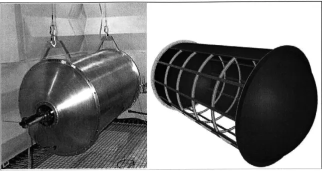
Figure 2.1: Testbed in anechoic chamber and its CAD drawing.
Figure 2.1 shows a picture of the model fuselage and its CAD drawing. The dimen-sions of the testbed are 91 cm in diameter and 198 cm in length. The testbed consists of six ribs and twelve stringers (frame members) that divide it into sixty panel sub-sections. Each panel is 23.9 cm wide and 30.5 cm long. Similar to many realistic helicopters, the testbed was made of aluminum.
The testbed is one of the most important parts of a study to investigate feasible meth-ods of active structural acoustic control. It must represent the important characteristics of a realistic helicopter fuselage such as global and panel structural dynamics, interior acoustic dynamics, and structural acoustic coupling. The testbed was designed using a hybrid of geometric and dynamic scaling techniques based on the data collected from six aircraft-related structures. The frame and panel geometries of these structures were averaged while maintaining mass and stiffness properties. In addition, the sizes of the structures were
scaled to the diameter of the testbed (91 cm), which was limited by the anechoic facility constraints.
The simplest design would be a geometric scaling of the averaged structures. However, brutal geometric scaling requires components that are difficult and expensive to manufac-ture. Hybrid scaling parameters were used to maintain the essential structural-acoustic dynamics while ensuring manufacturability of the design [O'Sullivan, 1998]. These parameters include mass per length, length/radius, panel aspect ratio, 1st panel frequency/ 1st acoustic frequency, panel mass/mass air volume, and bending and torsional inertia of ribs and stringers. These scaling parameters capture three main characteristics of the sys-tem dynamics: global dynamics, panel dynamics, and the relative dynamics between frames and panels.
The global stiffness of a thin-walled cylinder is dictated by its thickness. Hence, to capture global dynamics, the global structural stiffness was approximated by smoothing the ribs and stringers to create a thin walled cylinder with constant thickness. Mass per length was used as an equivalent parameter to represent the smoothed thickness.
High frequency modal behavior of aircraft structures is dominated by panels. Hence, panels must be characterized separately. The aspect ratio of a panel determines its modal ordering and frequency spacing. Another important attribute of the panel is the relation-ship between panel frequency and acoustic cavity frequency. The ratio of these frequen-cies represents the degree of coupling between structural and acoustic disturbances. This ratio depends on various properties of the panel such as length, width, thickness and den-sity as well as speed of sound in air. These properties of the panel were chosen such that the ratio of 1st panel mode to 1st acoustic mode approximates that of a realistic structure. An exact analytical relation for this ratio appears in the literature [Blevins, 1979]. Another parameter that helps maintain the proper structural acoustic coupling between the panel
and the air is the mass ratio of the panel to a surrounding characteristic volume of air which turns out to be an expression of geometric scaling for homogeneous panels.
Frame members (ribs and stringers) also require appropriate characterization. These members add both local and global stiffness to the structure. The number of frame mem-bers of the testbed differs from that of a real structure. Hence, the total frame stiffness was characterized by the sum of the bending and torsional inertias. As the panel size increases, the stiffness and the cross-sectional area of the frames increase but the number of frame members decreases. This helps to maintain the relative deflection between the panels and the frame members.
The nose and the tail of a regular helicopter are fairly complicated and non-regular. Simplified rounded end-caps were designed to reduce cost and to avoid sensor/actuator placement on the ends of the structure. The end-caps are stiffer and more massive than the skin of the testbed. This reduces the structural and acoustic coupling between the end-caps and the cylindrical section of the testbed.
The final consideration of the testbed design is the placement of the rivets that were used to attach the panels to the frame. Fastener spacing was geometrically scaled with the rest of the aircraft parameters and corresponds roughly to one centimeter on the testbed. This spacing is less than a quarter wavelength of the highest frequency of interest and puts the fastener dynamics outside the frequency range of interest (> 9000 Hz).
The reader is referred to the literature [O'Sullivan, 1998] for a more detailed presenta-tion of testbed design. The next secpresenta-tion presents in detail the selecpresenta-tion and placement of the sensors and actuators to be used for the active structural control of the testbed.
2.2
Sensor and Actuator Selection
The selection of sensors and actuators has crucial importance in a structural control experiment. This is especially true for structures with light damping, high modal density and sensitivity to environmental changes. These aspects introduce modeling difficulties [MacMartin, 1994] and may lead to a control design that solely depends on the experimen-tal identification of open-loop transfer functions taken by using the sensors and actuators. Thus, it is important to choose sensors and actuators that provide good observability and controllability of the structural modes.
The need for sufficient observability and controllability introduces some practical requirements. Achieving authority over a significant portion of the fuselage requires a large number of distributed sensors and actuators. However, strict weight and space limita-tions render this requirement a rather formidable task to fulfill [O'Sullivan, 1998]. For this reason, the chosen sensors and actuators must be lightweight, compact, and easy to attach to the structure.
2.2.1 Actuator Selection
The actuator has primary importance in a structural control experiment. Space and weight limitations are usually strict. Therefore, the actuator needs to be light and compact. It must be able to excite the structural modes that couple well to the performance metric of the control problem [Fuller, 1991]. The actuator must also be able to provide the required gain without saturation [Crawley, 1999]. Some conceivable choices include electrome-chanical shakers that can be instrumented inside the testbed and active materials that can be attached on the structure to strain it directly.
An electro-mechanical shaker can apply force to a specific point. Although a shaker provides the advantage of simulating an almost ideal point force actuator, it is massive. In addition, it is relatively difficult to install on a structure. Using a large number of shakers
on the testbed could be somewhat infeasible. The selected actuator should be thin, light-weight and easy to install in large numbers.
Designing a novel lightweight active mechanism to strain the testbed is also a possibil-ity. However, such a mechanism would have to be placed inside the testbed, possibly by fixing it between the frame members. Placing a large number of these mechanisms inside the testbed would be difficult and time consuming. Further, producing such a design in large numbers would also be time consuming and costly.
The utilization of piezoelectric materials as actuators for structural control has received significant attention in recent years, primarily due to their light weight and sim-plicity. A piezoelectric material deforms upon application of a voltage which allows it to be used as an actuator.
There are two commonly used types of piezoelectric materials: ceramics such as PZT (Lead-Zirconate-Titanate) and polymers such as PVDF (Polyvinylidene-Fluoride). PVDF has been used as actuators to study active vibration control of cantilever beams [Bailey, 1985]. PZT is about twenty times stiffer than PVDF. An actuator requires a large stiffness for effective mechanical coupling to the structure. The dielectric constant which relates the free strain of a piezoelectric element to the applied voltage is an order of magnitude greater for PZT than PVDF. These two properties imply that PZT is a more appropriate actuator than PVDF [Brennan, 1995]. Researchers evaluated the effectiveness of piezocer-amic actuators in exciting steady-state resonant vibrations in cantilevered beams and achieved promising results [Crawley, 1987]. Others studied the active suppression of air-craft panel vibrations in the 100 -500 Hz frequency range using piezoceramic strain actu-ators and obtained up to 55% reduction in vibrational energy [D'Cruz, 1998].
Difficulties in using piezoelectric actuators do exist. The deformation of a rectangular piezoelectric actuator can be modeled as a combination of in-plane stretching and a couple
at each edge of the rectangle. Hence, it is difficult to assess fully the effects of a piezoelec-tric actuator on a structure without having an accurate three-dimensional model. In spite of this difficulty, using piezoelectric actuators in structural control experiments has been quite common in recent years.
PZT is commonly used in structural control experiments. It is relatively light, thin and commercially available in different shapes and sizes. Another advantage that PZT pro-vides is high endurance to temperature. This feature of the PZT allows it to be used in smart composites with embedded distributed actuators. One purpose for making these composites is to attach them on the fuselage to control structural vibration. As another alternative, the fuselage can be made of these smart composites. PZT is available in differ-ent types (such as PZT 5-A, and PZT 5-H) depending on the strain output produced by a given amount of voltage. PZT 5-A was chosen as the actuator for being able to provide rel-atively large amount of deformation for a given amount of voltage.
2.2.2 Sensor Selection
A typical helicopter fuselage tends to exhibit complicated dynamics such as high modal density, i.e., closely spaced natural frequencies, sensitivity to environmental param-eters and other uncertainties. These structural properties introduce serious modeling diffi-culties and stability problems. Hence, it is desirable to use a control system that guarantees stability and does not require an accurate model such as a positive real control system. A system G(s) is said to be positive real if Re[G(s)] 0 for all Re[s] 0. This implies that for s = jw, phase of G(s) is between -90 deg and +90 deg. Thus, G(s) is
guaran-teed to have a 90 deg of phase margin which implies guaranguaran-teed stability.
A common structural control technique is to use collocated and dual sensor/actuator pairs. In a collocated pair, sensing and actuation occur at the same point or area on the controlled structure. A dual pair actuates with a generalized force and senses a generalized
velocity. Thus, the product of the variables of a dual pair is power [Crawley, 1991]. In a collocated and dual pair, a transfer function taken from the actuator to the sensor would show alternating pairs of poles and zeros, resulting in a phase that is bounded by -90 deg and +90 deg. Further, a collocated and dual sensor/actuator pair provides a positive real system which is guaranteed to be stable. In this light, the sensor selection was centered around forming a collocated and dual pair with the PZT actuator.
Since the ultimate goal of the control experiment is to reduce the noise inside the fuse-lage testbed, the internal acoustic pressure is the primary performance metric. Hence, a pressure sensor, such as a microphone may appear as an attractive choice. However, a pressure sensor does not behave in a collocated manner with the PZT. A PZT patch induces local strain in the panel, while a microphone measures acoustic pressure: a quan-tity that is local to the air inside the testbed. Hence, using a PZT patch and a microphone would result in a great deal of dynamics between the actuator and the sensor. This implies that a transfer function taken from a PZT patch to a microphone would result in a large amount of phase lag which introduces difficulties in closing a feedback loop without hav-ing stability problems.
Accelerometers are also commonly used sensors in structural control experiments. They are commercially abundant, simple to attach on a structure like the fuselage testbed and are relatively easy to use. If placed in the vicinity of a PZT, an accelerometer may behave in a collocated manner up to a certain frequency. But an accelerometer can not be truly collocated with the PZT since it only senses translational motion of a point while a PZT patch provides strain in the plane that it actuates. Figure 2.2 shows a frequency response function that was taken by exciting a PZT bonded to a fuselage panel, with broadband random noise, and measuring the output of an accelerometer that is located on the center of the PZT.
0--o ~'-20 b--40 -60 I I -500 1000 1500 2000 2500 3000 3500 4000 4500 5000 0 -180 - -360 -540 -720 -900 -1080 500 1000 1500 2000 2500 3000 3500 4000 4500 5000 Frequency (Hz)
Figure 2.2: PZT to accelerometer transfer function.
Figure 2.2 shows that the accelerometer behaves in a collocated manner with the PZT for frequencies below 900 Hz. However, above 900 Hz, there is a significant amount of phase lag which could introduce stability problems in a feedback control loop. In addition, obtaining a large number of sufficiently sensitive, and small accelerometers may be quite costly. Another drawback is that an accelerometer is a relatively complicated electro-mechanical system. Using a large number of such devices in real aircraft could be unreli-able.
Piezoelectric materials can also be used as sensors for structural control. PVDF is a piezo-polymer that is commonly used as a strain sensor. It is economical, light, simple to use and easy to manufacture in various shapes. Furthermore, it is a good candidate to form a collocated pair with the PZT.
.P1T
PVDF
Panel
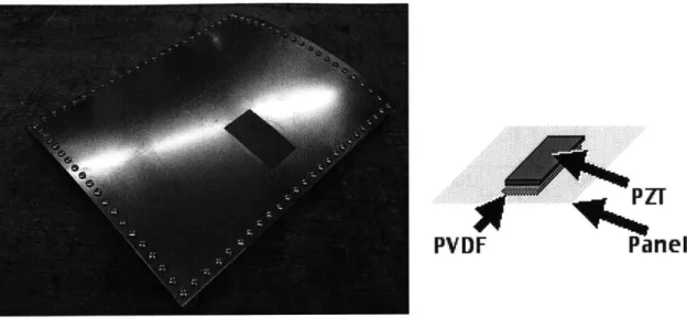
Figure 2.3: The curved panel and the schematic of the collocated PVDF-PZT pair.
Unlike the simple attachment of the accelerometer, bonding PVDF to a metal structure requires a strong glue such as epoxy. Removing an epoxy bond is difficult and has a ten-dency to damage the testbed. Hence, in order to try various bonding methods without dam-aging the testbed, an aluminum panel was made. The panel, as shown in Figure 2.3 has the same size, thickness, and curvature as of a testbed panel. It also has similar boundary con-ditions. A collocated sensor/actuator pair was made by bonding a PZT and a PVDF patch
on the opposite sides of the panel as shown in Figure 2.3.
Preliminary transfer functions were taken on this panel to assess the collocated behav-ior of the PVDF-PZT pair. Collocated behavbehav-ior only depends on the sensor and the actua-tor but not on the structure [Crawley, 1999]. Hence, a sensor/actuaactua-tor pair that shows collocated behavior on the panel is expected to show the same behavior on the testbed.
-10 -20 -30 -40 200 400 600 800 1000 1200 1400 1600 1800 2000 0 -90 . -180 -270 ( -360 -450 200 400 600 800 1000 1200 1400 1600 1800 2000 Frequency (Hz)
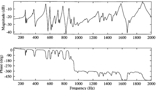
Figure 2.4: PZT to PVDF transfer function on the curved panel.
Figure 2.4 shows a PZT to PVDF transfer function obtained by exciting the PZT with a broadband random signal and measuring the voltage output of the PVDF. The sensor/ actuator pair shows collocated behavior below 950 Hz. Deviation from collocated behav-ior occurs at this frequency and phase lag starts to become significant. Surprisingly, the frequency range of collocated behavior for the designed PVDF-PZT pair is not greater than that of the accelerometer-PZT pair.
The main reason for the PVDF-PZT pair to lose collocation is the combined in-plane and bending actuation of the PZT. This causes the excitation of two types of modes: ones that are dominated by bending of the panel and ones that are dominated by the stretching in the panel. Hence, the local motion observed by the PVDF is a combination of these two kinds of modes. Having the PVDF and the PZT on the opposite sides of the panel results in a difference in the signs of the residues of the two modes.
PVDF
Kapton PZT
Panel
+-p
Figure 2.5: PZT-Copper kapton-PVDF patch.
As a result, a zero that occurs at a frequency between the two modal frequencies is "missed" by the sensor [Crawley, 1999]. A missing zero causes an immediate loss of phase at that frequency. In the case of this panel, a numerical study has shown that the first stretching mode occurs at 970 Hz. Hence, the zero that is supposed to occur near 950 Hz is missed. On the other hand, if the PVDF were on the same side as the PZT, bending and in-plane modal residues would have the same sign and a missing zero would not occur. For this reason, an alternative approach was taken by placing the PVDF and the PZT on the same side of the panel. Figure 2.5 shows this new arrangement.
A thin layer of kapton separates the PZT and the PVDF. The bottom side of the kapton is coated with copper to serve as the electrode for the hot (top) side of the PZT. In this par-ticular arrangement, the bottom side of the PZT is hard-wired to the panel. The panel is then grounded to serve as the ground for the PZT. Top side of the kapton is non-conduc-tive. Hence, the silver coating on both sides of the PVDF sheet is used as electrodes.
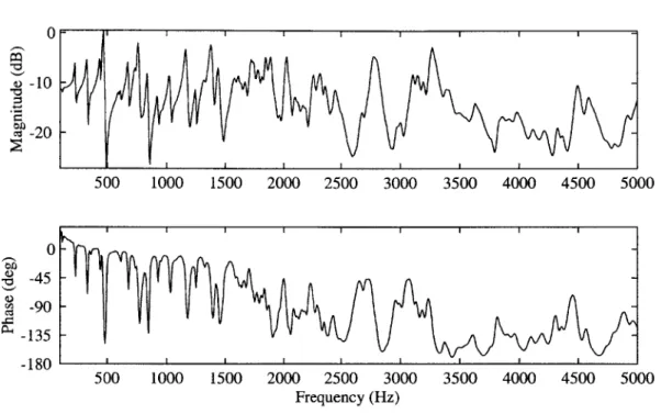
To test this sensor/actuator arrangement, the PZT was excited with broadband random noise to obtain an actuator to sensor transfer function.
W-0 10 m -20 500 1000 1500 2000 2500 3000 3500 4000 4500 5000 500 1000 1500 2000 2500 3000 Frequency (Hz) 3500 4000 4500
Figure 2.6: PZT to PVDF transfer function of the PZT-Copper kapton-PVDF patch.
Figure 2.6 shows that placing the PVDF on the same side as the PZT recovers the zero near 950 Hz and dramatically improves the frequency range of collocated behavior.
In summary, the sensor selection was based on forming a collocated pair with the PZT. Two different sensors were tested for the frequency range of collocated behavior: the accelerometer and the PVDF. Between the two sensors, PVDF showed the larger fre-quency range with collocated behavior. Primarily for this reason, it was selected as the control sensor.
The PZT-Kapton-PVDF patch was then bonded on the testbed to verify the frequency range of collocated behavior.
0 bO -45 -90 -135 -180 5000
-15 0-20 -25 -500 1000 1500 2000 2500 3000 3500 4000 4500 5000 0 S-90-- S-135--500 1000 1500 2000 2500 3000 3500 4000 4500 5000 Frequency (Hz)
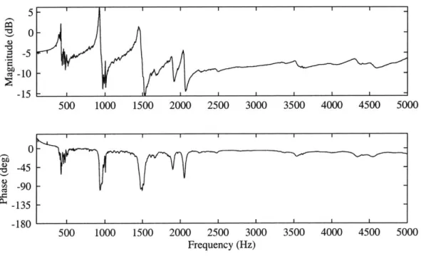
Figure 2.7: PZT-PVDF transfer function of the fuselage testbed.
Figure 2.7 shows a PZT to PVDF transfer function of the fuselage testbed. As expected, the sensor/actuator pair shows collocated behavior over a wide frequency range. The collocated behavior is preserved until 20 kHz which is the highest frequency that experimental equipment could record. The transfer function is plotted until 5000 Hz to better illustrate the high modal density below 2000 Hz. The following section presents the placement method of the chosen sensor/actuator pair.
2.2.3 Sensor and Actuator Placement
A common approach for maximizing the performance of a control experiment is to place the sensors and actuators at the antinodes of each mode in the control bandwidth. However, as Figures 2.2 and 2.7 illustrate, the number of modes that are in the frequency range of interest (0-2000 Hz) is fairly large. In addition, each mode of the structure is likely to have many antinodes. Thus, finding the shape of each mode and locating sensor! actuator pairs at its antinodes is not feasible.
There are numerical methods to assess observability and controllability with a limited number of sensors and actuators. If an accurate state-space model of the system is avail-able, one can calculate the controllability and observability gramians [Crawley, 1999] to quantitatively determine the observability and controllability of each mode.
O'Sullivan developed a state-space model of a cross section of the testbed to evaluate sensors and actuators as well as to study certain control algorithms [O'Sullivan, 1998]. The model was made two-dimensional in order to render the problem computationally feasible. An accurate three-dimensional model would require hundreds of thousands of degrees-of-freedom. With the computational limitations at hand, such a model would not be practical, especially for simulating closed-loop control algorithms.
The two-dimensional model is helpful in predicting the effectiveness of sensors and actuators and assessing the approximate performance of certain structural control algo-rithms. However, it can not be used to compute the observability and controllability grami-ans for a given placement of the sensors and actuators on the testbed, as the testbed is a three-dimensional structure.
Although the two-dimensional state-space model was not used with any numerical method, the results of the closed-loop control simulations provided valuable information to predict the appropriate size and location of the sensors and actuators.
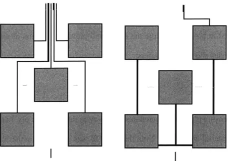
The numerical analysis of the two-dimensional model revealed that the sensors and actuators should be placed symmetrically around the center of each panel, covering approximately half of the panel size. A schematic of the proposed placement is given in Figure 2.8. The central patch is necessary to achieve authority over low frequency modes, whereas the patches in the corners provide observability/controllability over high fre-quency modes. The placement of piezo patches in the corners also provides some advan-tage in controlling the vibration of ribs and stringers.
Figure 2.8: Single panel sensor/actuator placement.
The numerical analysis of the two-dimensional model showed that although the inter-nal acoustic behavior strongly depends on the panel vibration, the motion of ribs and stringers also contributes to a certain extent. This implies that the motion of these frame members should also be controlled. Ideally, the most suitable actuator for the ribs and stringers would be a shaker. However, as was discussed earlier, instrumenting the testbed with a large number of electro-mechanical shakers would be extremely time consuming and costly. Furthermore, such an instrumentation would add a significant amount of mass which could change the dynamics of the structure. Frame members are much stiffer than panels. Hence, whether piezoceramics can provide significant authority over the frames is somewhat unclear. However, some level of actuation authority over the frames may be achieved by placing piezoelectric sensor/actuator pairs close to the corners of the panel.
In order to investigate the possibility of closing stable feedback loops on the testbed, one panel of the structure was instrumented with five collocated sensor/actuator pairs. Fig-ure 2.9 shows the five sensor/actuator pairs bonded on the testbed, based on the proposed placement method.
Figure 2.9: 5 PZT-Copper kapton-PVDF patches on a testbed panel.
-10
500 1000 1500 2000 2500 3000 3500 4000 4500 5000
500 1000 1500 2000 2500 3000 3500 4000 4500 5000 Frequency (Hz)
Figure 2.10: PZT to PVDF transfer function for the central patch of the panel.
5 0 -5 0 '*0 -15 0 -45 -90 -135 -180 I I I I I I I I I -. ... .. ... .... .. .... -..
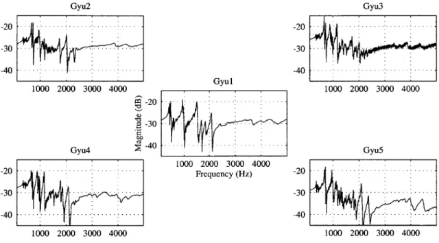
Gyu2 Gyu3 0 -.... - 0 -5 - -.-.- 5 -10 - - ...-..-. Gyul -15 1000 2000 3000 4000 -... -7---- ... 1000 2000 3000 4000 5 -0 -9 )-10 - - --. -.-. -. -.-. -Gyu4 -...-.- Gyu5 5 .... . .-. .. 1000 2000 3000 4000 5 - -..- -. Frequency (Hz) 0 0 -. --.-.-.. ...-. .-.. .-.-.--1 -10 1000 2000 3000 4000 1000 2000 3000 4000
Figure 2.11: PZT to PVDF transfer functions from 5 patches.
PZT to PVDF transfer functions were taken for each of the five sensor/actuator pairs to verify their functionality and collocated behavior. These transfer functions are shown in Figures 2.10 and 2.11. Figure 2.10 shows the typical pattern of a collocated transfer func-tion with alternating poles and zeros. Because the phase is bounded by 0 deg and -180 deg as opposed to -90 deg and +90 deg, the system is not positive real. This is because the sen-sor/actuator pair is not dual, i.e. the sensor measures a generalized displacement (strain) as opposed to a generalized velocity (strain rate). However, a positive real system may still be achieved by designing an appropriate controller. For example, the phase of the transfer function may be shifted up by +90 deg by differentiating the signal that is measured by the sensor. This issue will be discussed in further detail in Chapter 4 (control system design). Figure 2.11 shows the magnitude of transfer functions taken from all five sensor/actuator pairs. The subplots were arranged in a way similar to sensor/actuator placement scheme as
a visual aid. The phase plots of these transfer functions are not given in this figure to pre-vent redundancy.
Controlling the local vibration of a single panel of the testbed is unlikely to have a sig-nificant effect on the interior noise level or the vibration of a large portion of the structure. Thus, the main purpose of this instrumentation was not to achieve closed-loop perfor-mance but to assess the stability and feasibility of multiple separate classical feedback loops. Hence, details of this intermediate control experiment are not going to be presented here. Five independent simple control loops were stabily implemented using a PC. As a result, the structural acceleration in the panel was reduced by as much as 10 dB at certain resonant peaks over the frequency range of 100 -2000 Hz.
The results of the intermediate control experiment indicated that a larger number of testbed panels be instrumented with sensors and actuators. Further, a larger number of sen-sors and actuators are necessary to reduce the structural vibration over a significant portion of the structure. However, the performed instrumentation was lenghty and complicated. Further, as shown in Figure 2.9, there was a great deal of wiring. The wires were individu-ally connected to a terminal block for strain relief and then transferred to the computer. The dangling wires on the panel were secured with plastic tapes. Repeating this procedure on a larger number of panels could be excessively time consuming. As an immediate result, the study aimed towards developing an improved and more robust method of instru-mentation. An active ply with encapsulated sensors, actuators, and wiring was developed.
2.3 The Active Ply
The main goal for developing the active ply was to minimize the instrumentation time that is spent on the testbed. The testbed is a relatively massive structure and is not easy to move around. Neither is it convenient to work on.
8iricae sheet
tuna electroae sheet
electroe sheet
Figure 2.12: An exploded view of the active ply.
Instrumenting every component of the sensors and actuators on the fuselage individu-ally leads to numerous bonding steps and consumes a great deal of time. Instead, forming a ply that contains the sensors, the actuators and the wiring in it, reduces the number of instrumentation steps dramatically.
Figure 2.12 shows an exploded view of the active ply with encapsulated collocated PVDF-PZT pairs. The active ply has two sub-sections: the sensing ply and the actuation ply. The actuation ply has 5 PZT patches sandwiched between two layers of copper-kap-ton. Each kapton layer was etched to form an appropriate electrode and wiring pattern. The sensing ply was prepared in the same manner, only the sandwiched material was the PVDF. It was then glued on top of the actuation ply to form a single active ply. Fripp et al reported on the use of similar active plies for modal isolation techniques [Fripp, 1999].
Figure 2.13: Hot (on the left) and ground (on the right) electrode patterns.
2.3.1 Manufacturing and Bonding the Active Ply
Actuation Ply
The first step of the manufacturing procedure was to form the electrode pattern for the actuators. This was accomplished by etching a sheet of copper-kapton to form the appro-priate pattern. The actuation ply has two different electrode patterns: the ground electrode pattern and the hot electrode pattern. These patterns are shown in Figure 2.13.
The ground electrode pattern has five squares, each one corresponding to a PZT wafer. These squares are simply shorted to enable using a single ground source. The hot elec-trode pattern enables application of separate signals to each PZT patch. Each elecelec-trode pattern was printed on the copper coated side of a kapton layer, using a laser printer. Then, the printed section of the pattern was painted with a magic marker to form an etch mask. After that, the unpainted copper was etched using the Kepro Ferric-Chloride. Finally, the
mask paint was washed away with acetone. Five square PZT wafers (63.5mm x 63.5mm) were sandwiched between the ground and hot electrodes with epoxy. The sandwich was then placed in hot press to cure the epoxy and prevent formation of air bubbles between the electrodes and the PZT wafers.
Sensing Ply
The sensing ply was prepared the same way as the actuation ply. In this case, the sand-wiched material was PVDF. 2 mil thick PVDF was purchased in the form of 8.5x1 1 inch sheets. Each sheet had silver electrode coating on both sides. This coating was removed with acetone, and five squares, each being the same size as a PZT patch, were cut out of the sheet. These squares were then sandwiched between the hot and the ground electrodes with epoxy. The ply was then cured in the hot press.
As the final step of the manufacturing procedure, sensing ply was bonded on the actu-ation ply with epoxy. This was done carefully to ensure that the PVDF patches of the sens-ing ply were collocated with the PZT patches of the actuation ply. An additional sheet of copper-kapton was placed between the sensing and the actuation plies. Grounding this sheet during the control experiment serves as a shield against capacitive coupling between the two plies.
Figure 2.14 shows the picture a completed active ply. The plastic connectors were crimped onto the copper wiring at both ends of the active ply. Six active plies were manu-factured and bonded on the fuselage testbed for the active control experiment.
Figure 2.14: A finalized active ply.
The active plies were bonded on the testbed using a thermoplastic adhesive to mandate removing them easily, in case they needed to be replaced. The selected model for the cur-rent application was the 2.5 mil thick 3-M Thermobond 557EG which is the thinnest ther-moplastic adhesive available. The Thermobond is available in the form of 8.5x 11 inch polymer sheets. The sheet melts when heated; then, with the application of pressure, it forms a bond between the active ply and the structure. It is possible to break the bond and remove an active ply by simply reheating the adhesive. This is much easier than breaking bonds that are formed with strong liquid adhesives such as epoxy.
A thermoplastic polymer sheet was placed between each active ply and the fuselage testbed. Heat was applied by placing a Watlow flexible heater to the opposite side of the panel (inside the testbed). The required pressure was applied by means of a typical vac-uum bagging procedure: the vacvac-uum bag was taped to the structure, sealing off the active ply. Air was sucked out of the interior of the bag by means of a vacuum pump.
Figure 2.15: Testbed with six active plies.
Figure 2.15 shows the testbed after the bonding procedure has been completed. Rib-bon cables were used to connect the sensor/actuator pairs in the active plies to the control-lers. Two ribbon cables were connected to each active ply: one cable for sensors, one for actuators. Each ribbon cable contains ten lines: five hot lines and five ground lines. Hot lines, i.e., the lines that carry the sensor or actuator signals, and the ground lines were alternated to prevent cross-talk between the hot signals.
2.4 Finalized setup
The instrumentation of the testbed was completed by attaching the performance sen-sors that measure structural acceleration. An accelerometer was attached on the inside of each fuselage panel that was instrumented with an active ply. The microphone array had been instrumented during the development of the testbed itself.
Analog Controller Circuits Analog Controller Circuits
Data Acquisition & Disturbance Excitation
Figure 2.16: Schematic of the instrumented area of the testbed.
Figure 2.16 shows a schematic of the instrumented area of the testbed with the PVDF, PZT and accelerometer locations. The dark gray squares indicate the PVDF-PZT pairs, while black dots represent the accelerometer locations. The PZT patch bonded to the mid-dle panel (labeled "B") is the disturbance source. Figure 2.16 also illustrates the number-ing scheme of the panels, sensor/actuator pairs and accelerometers. For example, Panel 2, Location 1 corresponds to the central patch of the middle panel in the left-most column of Figure 2.15. The disturbance signal was generated using a PC with a Siglab interface. Out-puts of the performance sensors were measured with the same interface.
2.5
Summary
A setup was developed to study active structural control of a testbed which had been designed to represent many of the dynamic properties of a realistic aircraft fuselage. PZT (Lead-Zirconate-Titanate) was selected as the actuator primarily due to its light weight and ease of encapsulation. The sensor selection was based on forming a collocated pair with the PZT. An accelerometer and a PVDF (Polyvinylidene-Fluoride) patch were tested. Though lightweight and compact, the accelerometer did not behave in a collocated manner with the PZT over the desired frequency range (0-2000 Hz). The largest frequency range with collocated behavior occurred when a PVDF patch was superimposed on a PZT patch. Further, PVDF is light and simple to use. Hence, it was chosen as the sensor for this con-trol study.
Five square collocated PVDF-PZT pairs were bonded on a testbed panel and tested for observability/controllability of the structural modes. One pair was bonded to the center of the panel and the others were bonded to the four corners. After verifying that the chosen sensor/actuator pairs and the placement method provided acceptable observability/control-lability of many structural modes, an active ply was developed. The active ply contains the sensor/actuator pairs in an encapsulated package. Six active plies were manufactured and bonded on six panels of the testbed. Two kinds of performance sensors were used: acceler-ometers and microphones. Six acceleracceler-ometers were attached on the structure: one behind each panel that has an active ply. A number of microphones had been instrumented in the interior of the testbed in an earlier study and were used as the acoustic performance sen-sors for this study. The microphone array is located on the boom that runs accross the test-bed.
Chapter 3
Control System Design
This chapter presents the design of a controller for the testbed instrumented with collo-cated piezoelectric sensors and actuators, described in Chapter 2. The chapter starts with a brief overview of common control architectures. Low authority control, which is generally used to control localized modes is discussed. Further, a detailed description of common local control methods is presented. General benefits and disadvantages of these methods are evaluated by analyzing an arbitrary reduced order plant that exhibits resonant dynam-ics. Since an accurate model of the testbed does not exist, system identification techniques were used to assess the dynamics of the testbed and to design the control law. The results of system identification are presented with actuator to sensor and disturbance to perfor-mance transfer functions. Finally, the design of control law is presented in detail.
3.1 An Overview of Structural Control Architectures
In complicated structures, it is difficult to observe the exact system behavior and actu-ate the system in real time with a single central controller. For this reason, it is common to separate the system into smaller components that can be coped with individually [Siljak, 1991]. Generally, the control architecture is divided into levels with various degrees of authority on the structure.
A well-known approach to structural control is the use of a combination of high authority and low authority control (HAC/LAC). Generally, high authority control concen-trates on the global or low frequency modes that can be accurately modeled. Low authority
control is generally used for local or high frequency modes of the system, which tend to be difficult to model. A HAC controller usually operates on a multi-input multi-output (MIMO) basis, while LAC controllers can operate with separate local control loops, inde-pendent from the HAC controller. In other words, HAC and LAC controllers can use sepa-rate sensors and actuators [O'Sullivan, 1998]. Though this provides flexibility in implementing HAC and LAC controllers separately, in a complicated structure like an air-craft fuselage, control spillover problems may occur.
Hall et al. developed a hierarchic control scheme, which is a more sophisticated ver-sion of combined HAC/LAC control [Hall, 1991]. Their scheme offers the possibility of avoiding spillover by allowing HAC and LAC controllers to share information. Hence, HAC and LAC controllers are required to have some sensors and actuators in common. One disadvantage of this control scheme is that it requires full state feedback which is not feasible for a realistic structure.
As discussed in Chapter 2, the two-dimensional model of the testbed showed that frame members also contributed to interior noise generation by coupling to low frequency modes of the system. This implies that frame motion, i.e., the motion of the ribs and stringers, also needs to be controlled to maximize performance. Also discussed in Chapter 2 was the fact that the motion of panels couples well to the high frequency modes. Based on these facts, an appropriate control method would be to implement LAC controllers on the panels and HAC controllers on the frames of the structure [O'Sullivan, 1998].
Significant work has been done in controlling low frequency modes of aircraft. Greval et al. studied the narrowband control of global modes of a turboprop aircraft [Grewal, 1997]. They developed a high authority control method by placing piezoelectric actuators to match the deflection pattern of the aircraft at its blade passage frequency (approxi-mately 61 Hz). A weighted average of a group of accelerometers was used as the sensed