The Application of Network Coding to Multicast Routing in Wireless Networks by
Michael Jennings
B.A., Cornell University (2005)Submitted to the Department of Electrical Engineering and Computer Science in partial fulfillment of the requirements for the degree of
Master of Science in Electrical Engineering and Computer Science at the
MASSACHUSETTS INSTITUTE OF TECHNOLOGY June 2007
@
Massachusetts Institute of Technology 2007. All rights reserved.A uthor...
Certified by...
Accepted by ...
Department of Electrical Engineedng and Computer Science May 29, 2007 ... Dina Katabi Assistant Professor Thesis Supervisor Ch Chairman, Department Committee on Graduate Students A C "S iNSTITUTE
AUG 16
2007
BARKERThe Application of Network Coding to Multicast Routing in Wireless Networks by
Michael Jennings
Submitted to the Department of Electrical Engineering and Computer Science on May 29, 2007, in partial fulfillment of the
requirements for the degree of
Master of Science in Electrical Engineering and Computer Science
Abstract
This thesis considers the application of network coding and opportunistic routing to im-prove the performance of multicast flows in wireless networks. Network coding allows routers to randomly mix packets before forwarding them. This randomness ensures that routers that hear the same transmission are unlikely to forward the same packets, which permits routers to exploit wireless opportunism with minimal coordination. By mixing packets, network coding is able to reduce the number of transmissions necessary to convey packets to multiple receivers, which can lead to a large increase in throughput for multicast traffic.
We discuss the design of a multicast enabled variant of MORE, a network coding based protocol for file transfer in wireless mesh networks, and evaluate this extension, which we call MORE-M, in a 20-node indoor wireless testbed. We compare MORE-M to a wire-less multicast protocol that takes an approach similar to that of wired multicast by using the ETX metric to build unicast routing trees. We also compare MORE-M to a multicast enabled variant of the ExOR routing protocol. Experiments show that MORE-M's gains increase with the number of destinations, and are 35-200% greater than that of ExOR.
We then consider the problem of video streaming in a wireless local area network for applications such as video conferencing. A network coding based protocol that uses op-portunistic receptions at clients is proposed. We evaluate the design in our testbed and demonstrate that the use of network coding and, in particular, the use of wireless oppor-tunism increase the quality of the video stream.
Thesis Supervisor: Dina Katabi Title: Assistant Professor
Acknowledgments
This thesis is the result of joint work with Szymon Chachulski and Dina Katabi. I owe tremendous thanks to both Szymon Chachulski and Dina Katabi and I owe a great deal of thanks to: Micah Brodsky, Sachin Katti, Asfandyar Qureshi, and Hariharan Rahul. Lastly, I'm thankful for the many open source tools that supported this work, particularly Click, Evalvid, and Madwifi. This research was performed while on appointment as a U.S. De-partment of Homeland Security (DHS) Fellow under the DHS Scholarship and Fellowship Program, a program administered by the Oak Ridge Institute for Science and Education (ORISE) for DHS through an interagency agreement with the U.S. Department of Energy (DOE). ORISE is managed by Oak Ridge Associated Universities under DOE contract number DE-AC05-000R22750. All opinions expressed in this paper are the author's and do not necessarily reflect the policies and views of DHS, DOE, or ORISE.
Disclaimer
Many of the ideas in this thesis are the result of close interaction with Szymon Chachulski. Together we worked on the development of MORE, an opportunistic routing protocol that exploits network coding. Szymon's work has focused on the design of MORE, while mine has focused on extending the protocol to support multicast.
Contents
1 Introduction
1.1 The Benefits of Network Coding ...
1.1.1 Network Coding Reduces Routing Overhead . . . . 1.1.2 Network Coding does not Require Coordination . . . . 2 Related Work
2.1 Wireless Multicast . . . . 2.2 Network Coding . . . . 2.3 Video Streaming . . . . 2.3.1 Background . . . . 2.3.2 Related Work on Wireless Video Streaming . . . . 3 An Overview of the MORE Architecture
3.1 Source . . . . 3.2 Forw arders . . . . 3.3 D estination . . . . 4 MORE-M: MORE for Multicast Traffic
4.1 The Design of MORE-M ...
4.1.1 Selecting the Forwarders for a Multicast Session 4.1.2 MORE-M's Transmission Strategy . . . . 4.1.3 Batch Completion . . . . 4.2 Implementation Details . . . . 8 9 10 11 14 14 15 16 16 19 22 23 23 24 25 25 25 26 28 29
4.2.1 Packet Header . . . 29
4.2.2 Flow State . . . 30
4.2.3 MORE-M Operation in Detail . . . 30
5 Evaluation 32 5.1 Testbed . . . 32 5.2 Performance of MORE-M . . . 32 5.2.1 Compared Protocols . . . 33 5.2.2 Setup . . . 34 5.2.3 Results . . . 34
6 Streaming Video in a WLAN 37 6.1 Design Overview . . . 37
6.2 Solutions to the Three Challenges . . . 39
6.3 Design Considerations . . . 41 6.3.1 Client Feedback . . . 41 6.3.2 Coding . . . 41 6.4 Implementation Details . . . 42 6.4.1 Packet Format . . . 42 6.4.2 Server Retransmission . . . 43 6.4.3 Client Decoding . . . 44 7 Evaluation 46 7.1 Testbed . . . 46
7.2 Performance of the WLAN Video Streaming Protocol . . . 46
7.2.1 PSNR: An Objective Video Quality Metric . . . 47
7.2.2 Compared Protocols . . . 48
7.2.3 Setup . . . 48
7.2.4 Results . . . 49
List of Figures
1-1 Network Coding Reduces Routing Overhead. . . . . 10
1-2 Network Coding does not Require Coordination. . . . . 12
4-1 MORE-M Header . . . . 29
4-2 MORE-M Operation in Detail . . . . 31
5-1 One Floor of our Testbed . . . . 33
5-2 Fig. 5-3 Topology . . . . 35
5-3 Throughput as a Function of the Number of Destinations . . . . 35
5-4 CDF of Throughput for 3 Destinations in a Random Topology . . . . 36
6-1 WLAN Video Streaming Protocol Playback Buffer and Nacking Scheme. . 40 6-2 WLAN Video Streaming Protocol Header. . . . 42
7-1 The WLAN Topology . . . 47
7-2 Streaming Bitrate of Akiyo-cif.yuv Encoded Video as a Function of GOP . 49 7-3 Percentage of Packets Received in 2 Client Experiment . . . . 53
7-4 Percentage of I Frame Packets Received in 2 Client Experiment . . . . 53
7-5 Percentage of P Frame Packets Received in 2 Client Experiment . . . . 54
7-6 Retransmissions in 2 Client Experiment . . . . 54
7-7 Utilization in 2 Client Experiment . . . . 55
7-8 Average PSNR for 2 Client Experiment . . . 55
List of Tables
3.1 Definitions. . . . 22 7.1 I Frame Loss Correlation . . . . 50
Chapter 1
Introduction
Wireless multicast is an important problem with applications to file distribution, delay tol-erant networks, home entertainment, and video conferencing. As more wireless networks are deployed on city-wide scales, and as mobile wireless devices continue to replace their immobile wired counterparts, this importance will increase.
This thesis explores the use of network coding and opportunistic routing to improve the throughput of wireless multicast. We focus on two types of applications for wireless net-works. We first consider file sharing, for which we propose MORE-M. MORE-M extends the recent opportunistic routing protocol, MORE [9], for multicast traffic. In MORE-M, forwarders randomly mix packets before forwarding them. This randomness limits spuri-ous transmissions among forwarders without the use of coordination. Like MORE, MORE-M is able to exploit wireless opportunism without the cross-layer scheduling of the ExOR protocol [7], which is of key importance, as such scheduling becomes even less feasible in a multicast setting. MORE-M's use of network coding leads to additional throughput gains in that, unlike other multicast routing protocols that use wireless opportunism, MORE-M does not have to perform a retransmission for every distinct packet loss experienced by a destination in the multicast group. We elaborate on these two points with detailed examples below.
The second application we consider is video streaming in wireless local area networks, as, for example, in wireless video conferencing. Video streaming differs from file sharing in that it does not require complete reliability, it is more sensitive to delay, and packets are
not homogeneous, but rather are of varying importance and exhibit dependencies according to the video compression scheme used and the type of compressed frame the packets belong to. We design a protocol to address the needs of wireless video applications. In particular, we consider packet inter-dependencies within the network coding based scheme we present, we use application-layer feedback to deal with losses, and we exploit the broadcast nature of the wireless medium to improve throughput.
We discuss the implementation of both designs and evaluate them in a wireless testbed. Our experiments reveal the following findings.
" For file transfer, MORE-M's throughput gains increase with the number of destina-tions. For 2-4 destinations, MORE-M's throughput is 35-200% higher than ExOR's. In comparison to multicast using traditional routing, the gain can be as high as 3x.
" For video streaming, our protocol's use of opportunistic receptions at the clients in-creases throughput roughly by a factor equal to the number of clients. Its use of network coding increases throughput by as much as 10% among 2 clients experiencing packet losses with relatively modest correlation in bandwidth-limited scenarios. With 6 clients and more correlated losses, the gains are slight. We believe this small improvement is due to the fact that our protocol does not use coding to achieve reliability, but further analysis is needed.
In the next section we discuss the benefits of network coding most relevant to this work. Chapter 2 presents a survey of related work. In Chapter 3 we give an overview of MORE. Chapter 4 describes the design of MORE-M, the performance of which is evaluated in Chapter 5. We discuss a network coding based solution for streaming video in wireless local area networks in Chapter 6. An analysis of this protocol's performance is given in Chapter 7. Chapter 8 concludes the thesis with a brief summary.
1.1
The Benefits of Network Coding
Network coding refers to the method of allowing routers inside the network to combine packets before transmitting them and has two important benefits relevant to multicast rout-ing. First, it decreases the number of transmissions necessary to route packets to multiple
0.5:
A
p
1p
2p
3p
2p
3p
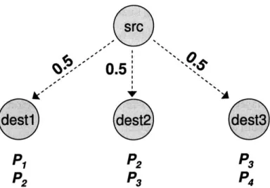
4Figure 1-1-Network Coding Reduces Routing Overhead. Instead of retransmitting all four
pack-ets, the source can transmit two linear combinations, e.g., P1 +P2 +P3 +P4 and p1+ 2p2 + 3p3 + 4p4.
These two coded packets allow all three destinations to retrieve the four original packets, saving the source 2 transmissions.
receivers for both multi-hop and single-hop routing. Second, it reduces the need for coor-dination among routers in multi-hop routing. More generally, network coding allows for a natural and efficient means of loss recovery in the face of low-quality wireless links and provides for economical path diversity, which is particularly important for multicast traffic in the unstable and lossy environments characteristic of wireless networks.
1.1.1
Network Coding Reduces Routing Overhead
How can network coding increase the throughput of multicast flows in particular? Put in-formally, statically packetizing the information to be conveyed to multiple receivers using a lossy broadcast medium increases routing overhead. Nodes receive different sets of packets and routers are forced to perform many transmissions in order to fill the distinct holes at the receivers. Network coding reduces this overhead by allowing routers to combine packets so that a single transmission can fill different holes at multiple receivers. We refer to this decrease in routing overhead as coding gain and illustrate how it can increase throughput in the following example.
In Fig. 1-1, the source multicasts 4 packets to three destinations. Wireless receptions at different nodes have been observed to be independent in prior work [39, 36]. Assume that each destination receives the packets indicated in the figui.e., the first destination
re-ceives pi and P2, the second destination receives P2 and p3, and the last destination receives
p3 and p4. Note that each of the four packets is lost by some destination.
Without coding, the sender has to retransmit the union of all lost packets, i.e., the sender needs to retransmit all four packets. In contrast, with network coding, it is sufficient to transmit 2 randomly coded packets. For example, the sender may send p1 = PI +P2 +P3 +P4 and p' = Pi + 2
P2
+
3P3 + 4p4. Despite the fact that they lost different packets, allthree destinations can retrieve the four original packets using these two coded packets. For example, the first destination, which has received '1, p' and pi, P2, retrieves all four
original packets by inverting the matrix of coefficients, and multiplying it with the packets it received, as follows:
Pi 1 11 P/
P2 1 2 3 4 P2
P3 1 0 0 0 Pi
P4 0 1 0 0 P2
Thus, in this simple example, network coding has reduced the needed retransmissions from 4 packets to 2, improving the overall throughput.
1.1.2 Network Coding does not Require Coordination
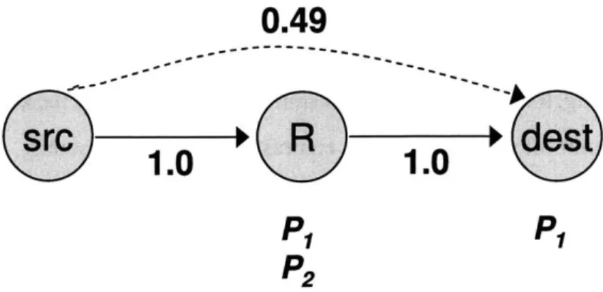
Consider the scenario in Fig. 1-2. Traditional routing predetermines the path before trans-mission. It sends traffic along the path "src-+R--*dest", which has the highest delivery probability. However, wireless is a broadcast medium. When a node transmits, there is always a chance that a node closer than the chosen nexthop to the destination overhears the packet. For example, assume the source sends 2 packets, pi and P2. The nexthop, R,
receives both, and the destination happens to overhear pl. It would be a waste to have node R forward pi again to the destination. This observation has been noted in [7] and used to develop ExOR, an opportunistic routing protocol for wireless mesh networks.
ExOR, however, requires node coordination, which is hard to achieve in a large net-work. Consider again the example in the previous paragraph. R should forward only
0.49
src
-
R
-.
dest
1.0
1.0
P1 P1
P2
Figure 1-2-Network Coding does not Require Coordination. The source sends 2 packets. The
destination overhears pi, while R receives both. R needs to forward just one packet but, without node coordination, it may forward pi, which is already known to the destination. With network coding, however, R does not need to know which packet the destination misses. R just sends the sum of the 2 packets p, + P2. This coded packet allows the destination to retrieve the packet it misses independently of its identity. Once the destination receives the whole transfer (p1 and p2), it acks the transfer causing R to stop transmitting.
packet P2 because the first packet has already been received by the destination; but, with-out consulting with the destination, R has no way of knowing which packet to transmit. The problem becomes harder in larger networks, where many nodes hear a transmitted packet. Opportunistic routing allows these nodes to participate in forwarding the heard packets. Without coordination, however, multiple nodes may unnecessarily forward the same packets, creating spurious transmissions. To deal with this issue, ExOR imposes a special scheduler on top of 802.11. The scheduler goes in rounds and reserves the medium for a single forwarder at any one time. The rest of the nodes listen to learn the packets over-heard by each node. Due to this strict schedule, nodes farther away from the destination (which could potentially have transmitted at the same time as nodes close to the destination due to spatial reuse), cannot, since they have to wait for the nodes close to the destination to finish transmitting. Hence the scheduler has the side effect of preventing a flow from exploiting spatial reuse.
Network coding offers an elegant solution to the above problem. In our example, the destination has overheard one of the transmitted packets, pi, but node R is unaware of this fortunate reception. With network coding, node R naturally forwards linear combinations of the received packets. For example, R can send the sum P1 +P2. The destination retrieves the packet P2 it misses by subtracting from the sum and acks the whole transfer. Thus, R
need not know which packet the destination has overheard.
Indeed, the above works if R sends any random linear combination of the two packets instead of the sum. Thus, one can generalize the above approach. The source broadcasts its packets. Routers create random linear combinations of the packets they hear (i.e., c1p1 +
. . .+ cp, where ci is a random coefficient). The destination sends an ack along the reverse
path once it receives the whole transfer. This approach does not require node coordination and preserves spatial reuse.
Chapter 2
Related Work
This chapter provides a brief survey of work in wireless multicast, considers practical net-work coding in the context of wireless netnet-working, and concludes with a discussion of video streaming.
2.1 Wireless Multicast
Considerable effort has been put into designing routing protocols for wireless multicast in MANETs [41, 37, 29], the On Demand Multicast Routing Protocol (ODMRP) being perhaps the most notable example. This work was motivated by the emergence of ad hoc networks for applications relevant to the military and first responders in disaster settings. Such protocols are most concerned with maintaining path availability in the face of random node movement and focus on reducing the resources required for routing packets. They use minimum-hop-count as the routing metric in an effort to take advantage of the wireless multicast advantage (WMA) [50]. WMA refers to the fact that in a wireless network where nodes use omnidirectional antennas, the wireless medium is shared and a single transmis-sion can reach more than one party. The design of a sophisticated routing metric able to quantify potential WMA usage along a specific route remains open. WMA is strongly re-lated to the notion of opportunistic routing [7], which refers to the objective of employing fortuitous receptions at routers that overhear local transmissions to improve routing effi-ciency, rather than depending on a static predetermined route. A substantial amount of
recent work in wireless networking is built around these two fundamental concepts.
Research in multicast for wireless mesh networks is more recent, as the technology fu-eling it is younger. This research is concerned with designing routing protocols to decrease delay, decrease the total number of transmissions, and/or increase throughput. WMNs are static and node failure is not a concern, so performance is of great importance. For ex-ample, some recent work has considered the important practical question of how to define high throughput routing metrics for protocols that use link layer broadcast instead of 802.11 DCF with ARQ in order to leverage WMA more effectively [40], but has limited itself to adapting MANET multicast routing protocols to the WMN setting. On the other hand, much work in designing these protocols is theoretical, for example [42] is concerned with constructing multicast trees that require very low bandwidth consumption. Other work in the field has been driven by more application-specific goals in mind (e.g. resiliency [51]).
In Chapter 4 we present a multicast enabled variant of MORE [9], called MORE-M. MORE-M is designed to be a practical, general-purpose multicast routing protocol for WMNs that naturally utilizes WMA and opportunistic routing without incurring some of the negative side effects that previously proposed protocols have. MORE-M preserves the architectural abstraction between the routing and MAC layers and is able to exploit spatial reuse, unlike the ExOR protocol [7], for example.
2.2
Network Coding
Work on network coding began with the pioneering paper by Ahlswede et al. that estab-lishes the value of coding in the routers and provides theoretical bounds on the capacity of such networks [3]. The combination of [32, 27, 19] shows that, for multicast traffic, lin-ear codes achieve the maximum capacity bounds, and coding and decoding can be done in polynomial time. Additionally, Ho et al. show that the above is true even when the routers pick random coefficients [18]. Researchers have extended the above results to a variety of areas including content distribution [16], secrecy [8, 20], and distributed storage [21].
Of particular relevance to this work is recent research on wireless network coding [34, 24, 25, 9]. This work can be divided into three classes. The first is theoretical; it extends
known information theory bounds from wired to wireless networks [34, 20]. The second is simulation-based; it designs and evaluates network coding protocols using simulations [38, 49]. The third is implementation-based; it uses implementation and testbed experiments to demonstrate achievable throughput gains for sensors and mesh networks [25, 22, 9].
In this thesis we design, implement, and evaluate network coding based wireless mul-ticast routing protocols in order to understand how network coding can improve mulmul-ticast throughput in practice. Our work and [9], upon which it is based, is distinct from prior research in network coding in that it is the first implementation-based work to consider wireless multicast.
2.3 Video Streaming
Multicasting video in a WLAN has become important to applications such as video con-ferencing and streaming multimedia. Here we provide some background material in video streaming that is relevant to the thesis and discuss related work.
2.3.1
Background
Video Compression
Compression is very important to video transport. An HDTV video signal, for example, would require 1.3 gbps of bandwidth in uncompressed form, but typical HDTV channel bandwidth is only 20 mbps [4]. Thus the signal must be compressed considerably without sacrificing perceived quality.
Under the MPEG-4 standard, video compression is accomplished via intraframe and interframe compression. Intraframe compression uses I frames, which compress the im-age of the original frame independent of preceding or succeeding frames in the stream by exploiting spatial redundancy within the pixels of the original frame. Interframe compres-sion, on the other hand, exploits temporal redundancy in the video stream by using P and B frames. A P frame uses intraframe compression and also references previous I or P frames in the encoded video frame sequence. A B frame references both preceding and succeeding
I or P frames and does not use intraframe compression. B frames are never referenced by other frames. Complete decoding of a P or B frame requires that the frames on which they depend be available. Since I frames are coded independently of other frames, they tend to be much larger than P frames, though this depends on the nature of the video encoded -it is true for the types of videos seen in the applications we would like to support, such as video conferencing. Compressed video is grouped into a series of group of pictures (GOPs). Each GOP begins with an I frame, followed by successive P frames and optionally B frames. The size of the GOP of a video encoding is a fixed parameter, as is the number of B frames used in each GOP. Thus the number of I, P and B frames of all GOPs is fixed and determined by the encoding parameters.
Video Streaming
In this work, we use an MPEG-4 part 2 standard-compliant [1] codec to encode YUV formatted video files. The MPEG-4 standard uses object-based compression. Individual objects within a scene are tracked separately and compressed together to create an MPEG4 file. Separate objects in a scene are separately encoded and decoded. This allows iden-tification and selective decoding of particular objects of interest and hence provides for interactivity and manipulation of content by allowing developers to control objects inde-pendently in a scene and makes MPEG-4 a good fit for multimedia compression and low bitrate transmission. An MPEG4 encoded file is converted into an MP4 container file with a hint track, resulting in an ISO compliant MPEG-4 stream. Hint tracks describe how the encoded frames should be packetized to support a streaming server or RTP and the con-verter takes parameters, such as the network MTU, to perform this conversion according to the network constraints (relying on IP fragmentation, for example, would lead to poor streaming performance). See [12] for a more complete discussion of this process.
The Challenges of Video Streaming
In this section, following the discussion in [4], we consider three main challenges that a transport protocol for video streaming faces. These challenges are not specific to wireless, but do become more difficult to address in a wireless environment. We also discuss the
means used for responding to these challenges. " Bandwidth Constraints:
Bandwidth is limited and variable in a wireless network, making some form of rate control necessary. The sender can provide for rate control by estimating the available bandwidth via probes or modeling and adapting the send rate accordingly. For example, [10] uses multiple TCP friendly rate control connections between the client and server in order to more fully utilize the wireless bandwidth while providing end-to-end rate control. Exploiting the broadcast nature of the medium increases the informational capacity of the network, and is also important in addressing this challenge.
" Delay Jitter:
Since the links in a wireless network generally experience a high rate of loss, the end-to-end packet delay is variable. However, packets in a video stream have a fixed play-back time indicating when they must be decoded for the corresponding frame to be displayed. A late packet is therefore useless, and, because of the nature of the encod-ing, can propagate errors to other frames, even if those frames are received by their deadline. Additionally, although frames must be received at a constant rate, they are generally not all the same size, for example, I frames tend to be much large than P frames. This burstiness introduces an additional variability to end-to-end packet delay. Clients use a playback buffer to address this problem. Frames are collected until the buffer is full, at which point playback begins. The buffer effectively adds an offset to the playback time of each frame. The trade off in designing a buffering scheme is to balance the desire to limit the consequences of packet lateness with the desire to avoid an overly long initial buffering delay, and is explored in [45]. One technique used to re-duce initial buffering delay is adaptive media playout [47], which involves decreasing the playback rate if the playback buffer has less frames than expected. The reduction in playback rate is generally small enough so as to be unnoticeable.
" Packet Loss:
Besides creating variable delay, poor quality wireless links result in considerable packet loss. To deal with this, one can use FEC, link layer retransmissions, or source coding. FEC has the advantage of a low delay if matched well to the channel, but will
re-quire high overhead for a highly variable channel with bursty losses. Retransmission schemes can be designed to optimize a particular metric or application-specific goal. For example, a RaDiO [11] streaming system selects the next packet to retransmit based on expected distortion reduction (assuming reception), the packet's deadline, channel statistics, and feedback information. The advantage of using a retransmission-based scheme is that it is adaptable and tunable, but the disadvantage is the necessary RTT latency. Lastly, source coding can be used to conceal errors in the decoding process or in the use of error resilient video coding. See [4] for a discussion of those methods.
2.3.2
Related Work on Wireless Video Streaming
Delivering content in a wireless network with strict timing constraints is a difficult prob-lem. Very low and variable bandwidth, high loss rates, contention among senders, packet collisions, background interference, and multipath fading make it very difficult to provide any performance guarantees and aggravate the problems discussed above. In this section we analyze the current techniques used for wireless video streaming.
[35] was the first to address the particular case of streaming over WLANs. They
pro-posed a simple hybrid ARQ algorithm that combined FEC and ARQ by having the client send an acknowledgment after decoding a batch of k packets to which FEC had been ap-plied. Other work has looked closely into particular aspects of video streaming in wireless. For example, [12] shows that the choice of encoding parameters is very important in a
wireless setting. In particular, they show that halving the hint track MTU values increases the medium access requirements by 20% on account of the increase in header overhead and the increase in the number of packets to transmit. They also show that there is little benefit to decreasing I frame frequency, as this leads to a marginal bandwidth gain at the cost of an encoding that is much more sensitive to packet loss.
The general transport mechanisms for wireless video streaming that have been devel-oped fall into two categories: application layer based and cross layer based. On the ap-plication layer side, packet scheduling is considered in [23]. They show that an earliest deadline first scheduling policy performs worse than a policy that takes into account the
relative importance of a frame within its GOP. Their frame-based scheduling approach as-signs a delay threshold to each frame which gives priority to frames that occur earlier in a GOP, since later frames in a GOP have a coding dependency on those frames. [11], mentioned above, describes a rate-distortion (R-D) optimized streaming system where a Lagrangian cost function is minimized by dividing time and bandwidth resources among packets. [46] proposes a simple frame dropping policy of discarding B frames when the network conditions become challenged, since B frames are the least important in a GOP, as no frame ever depends on them for its own decoding. [30] shows that adaptive sizing of the MAC layer frame in the presence of varying channel noise has a considerable effect on throughput and can be used to improve energy efficiency for the application's desired level of throughput. Path diversity is discussed in [48], where the focus is on the use of multiple description coding (MDC) and layered coding (LC). MDC is shown to be more effective when the application has specific delay constraints and long RTTs, while LC works well when a retransmission policy can be used along one of the paths.
Other solutions propose cross layer design (CLD) architectures. A timestamp-based content-aware adaptive retry (CAR) mechanism is proposed in [33]. A CAR-aided MAC judges whether to transmit a packet based on its retransmission deadline. This deadline is dependent on the packets temporal relationship and encoding dependencies with respect to other video packets in its GOP. CAR improves upon the design from [31] in that the retransmission decision is made after the completion of the most recent transmission, and thus in consideration of the playback schedule of the actual retransmission, which avoids late arrivals. A general CLD framework is outlined in [44]. They propose a layered CLD architecture and identify the parameters to be passed to the different network layers. Adaptive link layer techniques that adjust packet size, symbol rate, and constellation size according to channel conditions are used to improve throughput. At the MAC and net-work layers, the joint allocation of capacity optimizes throughput, while scheduling at the transport layer protects the video stream from packet losses while avoiding congestion.
The solution proposed in this thesis is at the application layer and is similar to many other application layer strategies in that it takes into account a frames relative impor-tance within its GOP. The contribution of our solution is that it is the first network coding
implementation-based approach to the problem. Additionally, we evaluate the design, and analyze the performance seen in our implementation.
Chapter 3
An Overview of the MORE Architecture
This chapter gives and overview of MORE, an opportunistic routing protocol that exploits network coding. In Chapter 4, we extend MORE to support multicast.MORE is a routing protocol for stationary wireless meshes, such as Roofnet [2] and community wireless networks [43, 5]. Nodes in these networks are PCs with ample CPU and memory.
MORE sits below IP and above the 802.11 MAC. It provides reliable file transfer. It is particularly suitable for delivering files of medium to large size (i.e., 8 or more packets). For shorter files or control packets, standard best path routing (e.g., Srcr [6]) can be used.
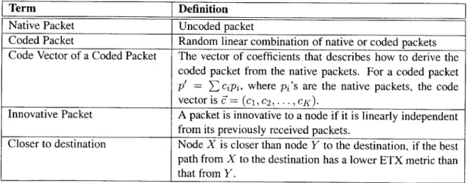
Table 3.1 defines the terms we use throughout this thesis.
Term Definition
Native Packet Uncoded packet
Coded Packet Random linear combination of native or coded packets Code Vector of a Coded Packet The vector of coefficients that describes how to derive the
coded packet from the native packets. For a coded packet
p' = E cipi, where pi's are the native packets, the code
vector is d= (ci, c2, .. ., CK).
Innovative Packet A packet is innovative to a node if it is linearly independent from its previously received packets.
Closer to destination Node X is closer than node Y to the destination, if the best path from X to the destination has a lower ETX metric than that from Y.
3.1 Source
The source breaks up the file into batches of K packets, where K may vary from one batch to another. These K uncoded packets are called native packets. When the 802.11 MAC is ready to send, the source creates a random linear combination of the K native packets in the current batch and broadcasts the coded packet. In MORE, data packets are always coded. A coded packet is p' = E cipi, where the ci's are random coefficients picked by the node, and the pi's are native packets from the same batch. We call C= (ci, ... , ci, ... , cK)
the packet's code vector. Thus, the code vector describes how to generate the coded packet from the native packets.
The sender attaches a MORE header to each data packet. The header reports the packet's code vector (which will be used in decoding), the batch ID, the source and desti-nation IP addresses, and the list of nodes that could participate in forwarding the packet. ETX [13] is used to compute the forwarder list. Specifically, nodes periodically ping each other and estimate the delivery probability on each link. They use these probabilities to compute the ETX distance to the destination, which is the expected number of transmis-sions to deliver a packet from each node to the destination. The sender includes in the forwarder list nodes that are closer (in ETX metric) to the destination than itself, ordered according to their proximity to the destination.
The sender keeps transmitting coded packets from the current batch until the batch is acked by the destination, at which time, the sender proceeds to the next batch.
3.2
Forwarders
Nodes listen to all transmissions. When a node hears a packet, it checks whether it is in the packet's forwarder list. If so, the node checks whether the packet contains new information, in which case it is called an innovative packet. Technically speaking, a packet is innovative if it is linearly independent from the packets the node has previously received from this batch. Checking for independence can be done using Gaussian elimination. The node ignores non-innovative packets, and stores the innovative packets it receives from the
current batch.
If the node is in the forwarder list, the arrival of this new packet triggers the node to broadcast a coded packet. To do so the node creates a random linear combination of the coded packets it has heard from the same batch and broadcasts it. Note that a linear combination of coded packets is also a linear combination of the corresponding native packets. In particular, assume that the forwarder has heard coded packets of the form
p = _' cjipi, where pi is a native packet. It linearly combines these coded packets to create more coded packets as follows: p" = E rjp', where rj's are random numbers. The resulting coded packet p" can be expressed in terms of the native packets as follows
p" = Ej (rj E> cjipi) = E> (E rjcji)pi; thus, it is a linear combination of the native packets themselves.
3.3
Destination
For each packet it receives, the destination checks whether the packet is innovative, i.e., it is linearly independent from previously received packets. The destination discards non-innovative packets because they do not contain new information. Once the destination receives K innovative packets, it decodes the whole batch (i.e., it obtains the native packets) using simple matrix inversion:
P1 c11 ... cK P J
PK CKI ... CKK PK
where, pi is a native packet, and p' is a coded packet whose code vector is - = c21, ... , CiK.
As soon as the destination decodes the batch, it sends an acknowledgment to the source to allow it to move to the next batch. Acks are sent using best path routing, which is possible because MORE uses standard 802.11 and co-exists with shortest path routing. Acks are also given priority over data packets at every node.
Chapter 4
MORE-M: MORE for Multicast Traffic
4.1
The Design of MORE-M
The basic design of MORE-M is very similar to that of MORE. The source transmits ran-dom linear combinations from a batch of K native packets and the forwarders transmit random linear combinations of the innovative packets they receive. Traffic is source-driven and forwarder transmissions are triggered by the reception of packets from upstream. A batch is completed when all destinations in the multicast group have delivered acks to the
source.
4.1.1
Selecting the Forwarders for a Multicast Session
Opportunistic routing does not use a fixed path to route packets. A set of forwarders and an ordering among the forwarders is all that is required; the actual path of the flow varies dynamically with the underlying conditions of the network. In MORE, the source con-siders any node in the network that has a lower ETX to the destination than itself as a potential forwarder for unicast traffic. ETX gives a natural ordering among the forwarders that MORE inherits in order to determine which forwarder is upstream of another. MORE uses a heuristic to determine the expected number of transmissions that forwarders will need to make for every source transmission and then prunes forwarders from the forwarder set if they make less than 10% of the total expected number of transmissions required to
route a batch of K packets to the destination. This pruning is done in order to limit the inefficiencies that would result from excessive contention.
MORE-M builds upon MORE's approach to determine the forwarder set. For each destination in the multicast group, MORE-M uses MORE's technique to obtain a forwarder set for the unicast flow from the source to that destination. The set of forwarders used by MORE-M for multicast traffic is the union of all forwarders obtained via this process. Forwarders are totally ordered using the ETX from the source to each forwarder. If the source has a lower ETX to forwarder i than to forwarder
j,
then forwarder i is considered upstream of forwarder j.4.1.2
MORE-M's Transmission Strategy
Any routing protocol has to address two fundamental questions after determining a group of forwarders: When should forwarders transmit packets, and how many packets should be transmitted? The hop-by-hop retransmission method used by traditional routing cannot be applied in the context of MORE. This is because in opportunistic routing a next hop is not chosen until after transmission, and thus can vary across transmissions. MORE ad-dresses these questions in two steps. First, MORE estimates the number of transmissions a forwarder must make for each source transmission in order to guarantee that a forwarder closer to the destination than the transmitting forwarder will receive the packet being for-warded. Second MORE legislates that forwarders transmit packets in proportion to this number according to a reception-driven transmission policy.
Let N be the number of nodes in the network. For any two nodes, i and j, let i < 3
denote that i has a smaller ETX than
j.
Let pij denote the loss probability in sending a packet from i toj.
Let zi be the expected number of transmissions that forwarder i must make to route one packet from the source, s, to the destination, d. We assume that wireless receptions at different nodes are independent, an assumption that is supported by prior measurements [39, 36].Let us calculate the number of packets that a forwarder
j
must forward to deliver one packet from source, s to destination, d, or, in other words, the load, Lj, on forwarder j. Theexpected number of packets that
j
receives from nodes with higher ETX isEZ
2>
3 zi(1-pij). For each packetj
receives,j
should forward it only if no node with lower ETX metric hears the packet. This happens with probability F1k,< Pik. Thus, in expectation, the number of packets that j must forward, denoted by Lj, is:Lj = Z(zi(1 - pij) 11pik). (4.1)
i>j k<j
Note that L, = 1 because the source generates the packet.
Now, consider the expected number of transmissions a node
j
must make. j should transmit each packet until a node with lower ETX has received it. Thus, the number of transmissions thatj
makes for each packet it forwards is a geometric random variable with success probability (1 - Hk<j Pik). This is the probability that some node with ETX lower thanj
receives the packet. Knowing the number of packets thatj
has to forward from Eq. 4.1, the expected number of transmissions thatj
must make is:z-= ( H 3 (4.2)
From this we know the number of transmissions, zi, that forwarder i should make for every packet sent by the source. Intuitively, we think of zi as the amount of credit forwarder i is given for each source transmission. MORE legislates a reception-driven transmission policy for the forwarders, as most forwarders will not be able to detect when a packet was transmitted by the source. Define the TX-credi t of a node to be the number of transmissions that a node should make for every packet it receives from upstream. For each packet sent from source to destination, node i receives EZ~i(1 - pji)zj, where zj is the number of transmissions made by node
j
and (1 - pji) is the delivery probability fromj
to i. Thus, the TX-credit of node i is:
z-TXcrediti = . (4.3)
EZ>i z3 (1 - pji)
In MORE-M forwarder i is assigned the maximum zi credit that it would receive in any of the unicast flows to a destination in the multicast group. TX-crediti is then computed
by considering all upstream nodes in the multicast forwarder set using Eq. 4.3. Assigning the maximum credit helps to ensure that the forwarder will have enough credit to forward the load it receives from upstream to each destination that it is a forwarder for. Forwarder i keeps a credit counter that is incremented by TX-crediti when a packet is received from upstream. When forwarder i has the opportunity to transmit a packet, it checks the credit counter. If it is positive, the forwarder transmits the packet and decrements the credit counter by 1. If it is not positive, the forwarder does nothing.
4.1.3
Batch Completion
Once a destination in the multicast group is able to decode the current batch, an ack is sent to the source. An ack is given priority over data and local retransmissions are used at each hop to reliably deliver an ack along the minimum ETX path from the destination to the source. The source does not move onto the next batch until all destinations in the multicast group have acked the current batch.
As destinations ack the batch, the forwarders that were included in the forwarder set become superfluous and will generate spurious transmissions as they receive packets for destinations in the multicast group for which they are not forwarders. These spurious transmissions will generate even more spurious transmissions. In order to address this problem, whenever a destination acknowledges the current batch, the source recomputes the credit, zi, for each forwarder i, as the maximum credit taken over only those hypothet-ical unicast flows to the destinations that have not yet acked the batch. For each forwarder
i, TX-credit is then computed over the active upstream forwarders in the multicast group
forwarder set. The source places this updated TX-crediti assignment in the header of packets transmitted thereafter. The forwarders that receive these packets update their state accordingly.
IC) M: CD CD ACK Bitmap a Number of ACK FWDs I ACK FWD IP -0 Number of FWDs FD IP TXCredit 0
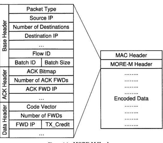
Figure 4-1-MORE-M Header.
4.2
Implementation Details
4.2.1
Packet Header
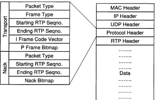
MORE-M inserts a variable length header in each packet, as shown in Fig. 4-1. The type field distinguishes data packets from acks. The source IP address, the IP address of each destination, flow ID, batch ID, and batch size follow. For ack packets, an ack bitmap is included in the header which indicates which of the destinations has acked the batch. Ack headers also contain the list of forwarders to use ordered according to the minimum ETX path to the source. For data packets, the code vector follows and identifies the coefficients that generate the coded packet from the native packets in the batch. Data headers also contain the list of forwarder IP addresses ordered according to their proximity to the source. For each forwarder i, the data header contains TX-creditj as well.
Packet Type Source IP
Number of Destinations Destination IP
Flow ID
Batch ID Batch Size
MAC Header
MORE-M Header
4.2.2
Flow State
Each MORE-M node maintains per-flow state created on reception of the first packet from a flow that has the node's ID in the list of forwarders. This soft state is timed out after 5 minutes of no activity. The state includes:
" The batch buf f er stores the received innovative packets. Note that the number of innovative packets in a batch is bounded by the batch size K.
" The current batch variable identifies the most recent batch from the flow.
" The forwarder list contains the list of forwarders and their corresponding TX-credits, ordered according to their proximity to the source.
" The credit counter tracks the transmission credit. For each packet arrival from a node with a higher ETX, the forwarder increments the counter by its corresponding TX-credit, and decrements it by 1 for each transmission. A forwarder transmits only when the counter is positive.
4.2.3
MORE-M Operation in Detail
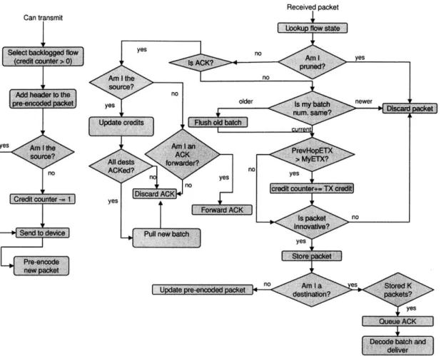
Figure 4-2 shows the MORE-M operation in detail. A forwarder prepares a pre-coded packet for flows that have positive credit counters in order to avoid adding unnecessary delay to transmissions. The forwarder chooses among flows in round-robin order. A new packet is pre-coded for the currently selected flow and stored for future use immediately
after transmission and the flow's credit counter is decremented by 1.
The handling of receptions depends on whether the node is the source, a forwarder, or a destination. The node first determines the type of the packet. The handling of acks is described below. The source discards data packet receptions. A forwarder checks the batch ID of the data packet. If it is higher than the forwarder's current batch, the forwarder updates its current batch and flushes packets from older batches from the batch buffer. If the packet was transmitted from upstream, the forwarder checks first whether its TX-credit must be updated and then increments the flows credit counter by its updated TX-credit. Innovative packets are added to the batch buffer while non-innovative packets are discarded. The forwarder's pre-coded packet for this flow is updated by adding the recent packet
Received packet
L~oupfowsatJ
yes no C counter- 1 Pre-encode now packet] AC ed? n DiscardACK yesPull new batch
no
Up e r-noe es
yes
Queue ACK
I
Figure 4-2-MORE-M Operation in Detail. The figure gives a detailed presentation of how
MORE-M works.
multiplied by a random coefficient. A destination checks if the reception completes the batch, and queues an ack if so.
As noted above, ack packets are routed to the source along the shortest ETX path. Acks are prioritized over data packets and transferred reliably using link layer retransmis-sions. Source routing is used by the destination and the list of ack forwarders is placed in the MORE-M header so that the multicast forwarders know whether to forwarder the ack onward. All forwarders in the multicast forwarder set that overhear an ack update their current batch variable and flush packets from the acked batch from their batch buffer. Once the source receives an ack, it checks to see if all destinations have acked the batch. If so, a new batch is pulled. Otherwise, the source recomputes the TX-credits to take into account only the active destinations, as describe above, and uses the updated TX-credits in future transmissions. Can transmit Tf yes newerckt no yes SForwardiACK d yes
redit counter+= TX credt
no yes IF yes I Cno A iI I the no prn irce? n older Is my b num. sa
e credits Flush okd batch
Chapter
5
Evaluation
In this chapter we conduct a performance evaluation of MORE-M.
5.1
Testbed
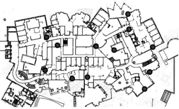
(a) Characteristics: We have a 20-node wireless testbed that spans three floors in our building connected via open lounges. The nodes of the testbed are distributed in several offices, passages, and lounges. Fig. 5-1 shows the locations of the nodes on one of the floors. Paths between nodes are 1-5 hops in length, and the loss rates of links on these paths vary between 0 and 60%, and averages to 27%.
(b) Hardware: Each node in the testbed is a PC equipped with a NETGEAR WAG311 wireless card attached to an omni-directional antenna. They transmit at a power level of 18 dBm, and operate in the 802.11 ad hoc mode, with RTS/CTS disabled.
(c) Software: Nodes in the testbed run Linux, the Click toolkit [28] and the Roofnet soft-ware package [2]. Our implementation runs as a user space daemon on Linux. It sends and receives raw 802.11 frames from the wireless device using a libpcap-like interface.
5.2
Performance of MORE-M
We use measurements from a 20-node wireless testbed to evaluate MORE-M and compare it with a variant of ExOR extended for multicast traffic. We also compare MORE-M to
Figure 5-1-One Floor of our Testbed. Nodes' location on one floor of our 3-floor testbed.
a traditional best path routing protocol that adopts the same approach as wired multicast to form an MST among nodes in the multicast group using the ETX metric. We note the following results:
" MORE-M's throughput gain increases with the number of destinations. For 2-4 des-tinations, MORE-M's throughput is 35-200% larger than ExOR's. In comparison to traditional multicast routing, the gain can be as high as 3x.
" In terms of overhead, MORE-M stores the current batch from each flow. Our imple-mentation supports up to 44 mbps on low-end machines with Celeron 800MHz CPU and 128 kilobytes of cache. Thus, the overhead is reasonable for the environment it is designed for, namely stationary wireless meshes, such as Roofnet [2] and community wireless networks [43, 5]. See [9] for a discussion of this result.
5.2.1
Compared Protocols
We compare the following three protocols: * MORE-M as described in Chapter 4.
" ExOR [7], the current opportunistic routing protocol. ExOR does not have multicast
extensions. Thus, we must define how it deals with multicast. The extension must exploit WMA and opportunistic receptions. The protocol works by determining the ExOR forwarders for each destination. The per-destination forwarders use the ExOR protocol to access the medium and coordinate their transmissions. In contrast to unicast
ExOR, if the forwarders toward destination X opportunistically hears a packet by a forwarder in the forwarder list of destination Y, it exploits that opportunistic reception. Said differently, we allow opportunistic receptions across the forwarders of various destinations.
* Srcr [6] which is a state-of-the-art best path routing protocol for wireless mesh net-works. It uses Dijkstra's shortest path algorithm where link weights are assigned based on the ETX metric [13] and uses the wired multicast approach to form an MST among nodes in the multicast group.
5.2.2
Setup
In each experiment, we run Srcr, MORE-M, and ExOR in sequence between the same source destination pairs. Each run transfers a 5 megabyte file. We leverage the ETX im-plementation provided with the Roofnet Software to measure link delivery probabilities. Before running an experiment, we run the ETX measurement module for 10 minutes to compute pair-wise delivery probabilities and the corresponding ETX metric. These mea-surements are then fed to all three protocols, Srcr, MORE-M, and ExOR, and used for route selection.
Unless stated otherwise, the batch size for both MORE-M and ExOR is set to K = 32 packets. The packet size for all three protocols is 1500 bytes. The queue size at Srcr routers is 50 packets. In contrast, MORE-M and ExOR do not use queues; they buffer active batches. The experiments are performed over 802.1 lb with a bit-rate of 5.5 mbps.
5.2.3
Results
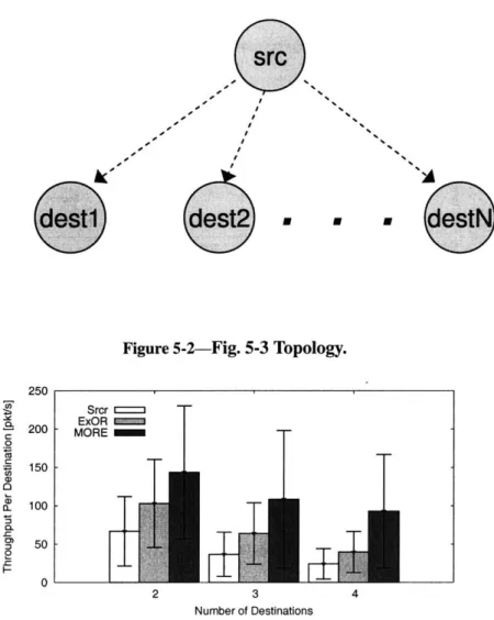
Our results show that MORE-M's throughput is significantly higher than both ExOR and Srcr. In particular, we experiment with the simple topology in Fig. 5-2, where the source multicasts a file to a varying number of destinations. Fig. 5-3 shows the average through-put as a function of the number of destinations. The average is comthrough-puted over 40 dif-ferent instantiations of the topology in Fig 5-2, using nodes in our testbed. As expected, the per-destination average throughput decreases with increased number of destinations.
% A
dest
dest2
-destN
Figure 5-2-Fig. 5-3 Topology.
250 Srcr 20 ExOR 200 -MORE 0 Ca 150 Ca 100 CL 2 50 -0 2 3 4 Number of Destinations
Figure 3-Throughput as a Function of the Number of Destinations for the Topology in Fig. 5-2. The figure shows the per-destination throughput of MORE-M, ExOR, and Srcr. The thick bars show the average per-destination throughput taken over 40 runs with different nodes. The lines show the standard deviation.
Interestingly however, the figure shows that MORE-M's throughput gain increases with in-creased number of destinations. MORE-M has 35-200% throughput gain over ExOR and
100-300% gain over Srcr.
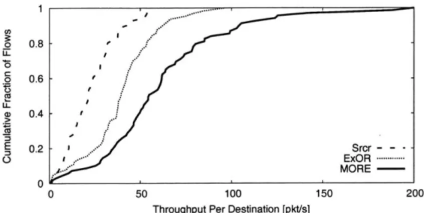
Next, we run multicast over random topologies and multihop paths. We pick a source and 3 destinations randomly from the nodes in the testbed. We make the source multicast a file to the three destinations, using MORE-M, ExOR, and Srcr. We repeat the experiment for 40 different instantiations of the nodes, and plot the CDFs of the throughput. Fig. 5-4 confirms our prior results showing significant gain for MORE-M over both ExOR and Srcr. In this figure however the difference between MORE-M and ExOR is less pronounced than in Fig. 5-3. This is because the CDF uses random topologies with all nodes in the testbed
o 0.8 -.20 . C LL a) 0.4 E 0.2 ' Srcr - - -O , .. ExOR --- MORE-0 0 50 100 150 200
Throughput Per Destination [pkt/s]
Figure 5-4-CDF of Throughput for 3 Destinations in a Random Topology. The figure shows
the CDF of the per-destination throughput of MORE-M, ExOR, and Srcr. For each run, a source and 3 destinations are picked randomly from among the nodes in the testbed.
potentially acting as forwarders. This increases the potential for opportunistic receptions and thus makes the relative gain from network coding look less apparent.
/ -1
Chapter 6
Streaming Video in a WLAN
In this chapter we design an opportunistic routing protocol that is suitable for video stream-ing over a WLAN. Video streamstream-ing differs from file transfer in that it does not require complete reliability, it is more sensitive to delay, and packets are not homogeneous. Our protocol addresses these differences as well as the particular challenges described in Chap-ter 2.
6.1
Design Overview
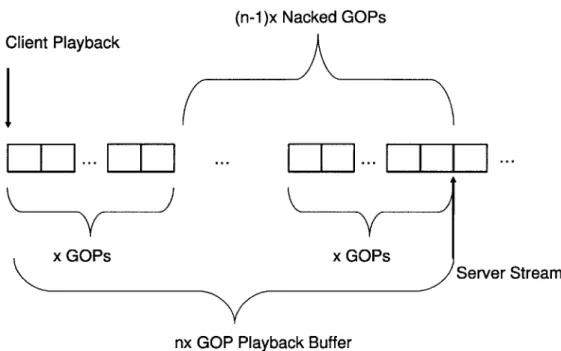
The server broadcasts packets in the stream to the clients. The clients play the stream in synch one playback buffering interval behind the stream at the server. The playback buffer itself is equal to the time required to play nx GOPs, where n > 2 and x > 1, and a GOP consists of one I frame followed by 4 or more P frames. The clients send periodic nacks reliably using link layer retransmissions every x GOPs (see fig. 6-1). These nacks indicate which packets in the (n - 1)x GOPs that have most recently been streamed by the server must be retransmitted. The server performs retransmissions when spare bandwidth is available.
The server retransmits packets in order of earliest deadline. Within a GOP, the server uses random linear codes to retransmit the lost I frame packets. Rather than nacking par-ticular I frame losses, the clients simply nack the first k packets of an I frame, where k is the number of innovative packets necessary to achieve full rank for decoding. In order to
retransmit the lost I frame packets, the server determines the maximum number of innova-tive packets needed by a client for decoding and broadcasts that number of random linear combinations of I frame packets. Random linear codes are used for I frame packet retrans-missions in order to reduce the number of transretrans-missions required to fill the holes at the clients. Recall from Chapter 1 that we called this decrease in overhead coding gain. Since losses are experimentally observed to be independent [39, 36], clients will lose different I frame packets. The size of the union of losses among clients will be larger than the number of innovative packets required by any particular client. Since I frames span many packets, the use of random linear codes leads to a more efficient use of bandwidth.
After broadcasting coded I frame packets, the server retransmits lost P frame packets in order of earliest deadline. Packets coded with random linear codes generally cannot be decoded until full rank is attained among the code vectors of the packets. For the encoded videos of the applications we'd like to support there are not enough packets in a P frame to consider applying linear codes to just the packets of the frame, while coding over multiple P frames is not ideal because, if full rank is not achieved, one would be unable to decode multiple P frames. For these reasons, random linear codes are not used for retransmitting packets belonging to P frames. However, to improve efficiency, the server uses a greedy coding algorithm to decrease the total number of retransmissions of P frame packets. The server considers the next P frame packet pi to retransmit and determines which clients have not nacked pi, and then searches for the packet pj of a P frame with earliest deadline that was nacked by at least one of those clients, but not by the clients that nacked pi. If such a packet is found, it is XORed with pi. Note that pj can be taken from among (n - 1)x GOPs if the server has streamed all packets in the buffering interval. The server repeats this coding process until no such packet can be found or until the coded packet pi consists of packets such that every client has nacked exactly one of them and every client can decode the transmission based on its current state. See Algorithm 1 for a more formal presentation of the server's retransmission algorithm.