Applicability of Undermatched Welds for High
Strength Steel Structures
by
Nikolaos K. Kafetsis
B.S. in Marine Engineering Hellenic Naval Academy, 1985Submitted to the Departments of Ocean Engineering and Materials Science and Engineering
in partial fulfillment of the requirements for the degrees of
Naval Engineer
and
Master of Science in Materials Science
at the
,,.5,-.AC;.US:;.,TS I ;1,S6 $ iL
OF TECHNOLOGY
DEC 0
8
1995
LIBRARIES MASSACHUSETTS INSTITUTE OF TECHNOLOGY
June 1995
@ Massachusetts Institute of Technology 1995. All rights reserved.
Author ... ... z.... .,.. 1...
Department of Ocean Engineering May 12, 1995
Certified by ...
Koichi Masubuchi, Kawasaki Professor of Engineering Thesis Supervisor, Department of Ocean Engineering
Certified by ... ... ...
Frederick J. McGarry, Profeser'-ýFi Engineering and Polymer Thesis Reader, Department of Materials Science and Engineering Accepted by ...
A. Douglas Carmichael, Professor of Po~Engineering Chair, Departmental Committee on Graduate Students A ccepted by ... ...
Carl V. Thompson II, Professor of Electronic Materials Chair, Departmental Committee on Graduate Students
Applicability of Undermatched Welds for High Strength
Steel Structures
by
Nikolaos K. Kafetsis
Submitted to the Departments Ocean Engineering and Materials Science and Engineering on May 12, 1995, in partial fulfillment of the
requirements for the degrees of Naval Engineer
and
Master of Science in Materials Science
Abstract
This study presents experimental and numerical results for the strength of welded joints, made on high strength steels with different degrees of strength matching. The steels involved are the HY-100 and HY-130 U.S. Navy, quenched and tempered steels. The test methods are the self restraint cracking test, the tensile test and the fatigue test. The investigated parameters are the strength of the weld metal and the preheat temperature.
The self restraint cracking test does not show clearly the expected results, that the required preheat temperature to avoid cold cracking can be reduced by applying undermatched welds at the root of the welding. This conclusion was reached in a similar experiment that was performed on HT-80 high strength steel.
The tensile test and the numerical analysis show that the strength properties of the undermatched weld are not the typical properties of the unrestrained weld material. They are greatly elevated due to the restraint effect provided by both the base metal and the stronger surrounding weld metal.
Results from the fatigue test show that the degree of strength undermatching, does not affect significantly the crack propagation rate at the joint.
Thesis Supervisor: Koichi Masubuchi Title: Kawasaki Professor of Engineering
Acknowledgments
I would like to express my gratitude to my advisor Professor Koichi Masubuchi for his guidance and support. I am also grateful to Professor F. McGarry for his advice. Special thanks to Akira Umekuni for his involvement and suggestions throughout this thesis. His help was invaluable.
I would also like to thank D. Fitzerald and F. Gaudette for their assistance dur-ing the tests, Juliana Atmadja and Platon Velonias for their help with the ADINA program, Spyros Maragos for his advice and comments on writing and presenting this thesis, and Muriel Bernier for proof-reading the text.
Finally, I would like to thank my wife Athena for her continuous support and understanding throughout my studies.
Contents
1 Indroduction
2 Background
2.1 Past studies on high strength steel welding ...
2.2 High-strength low-alloy quenched and tempered steels . 2.3 Weldability of quenched and tempered steels ... 2.4 W eldability test ...
2.5 Hot and cold cracking ... 2.6 Residual stresses ... 2.7 Degree of restraint ... 2.8 Fracture toughness ... 2.9 Fracture mechanics theory . ... 2.10 Fatigue fracture ...
3 Experimental Description and Results 3.1 Steel properties and electrode selection 3.2 Experimental results . . . .
3.2.1 Self-restraint cracking test . . . 3.2.2 Fatigue test . . . . 3.2.3 Tensile test . . . . 4 Numerical Analysis
4.1 Strength of plate with soft interlayer
12 . . . . 13 . . . . 19 . . . . 20 . . . . 21 . . . . 22 . . . . 24 . . . . 26 . . . . 28 . . . . 30 . . . . 32 34 35 42 42 57 65 67 68
4.2 Strength of restraint cracking test specimen . ... 77 4.3 Degree of restraint of the cracking test specimen . ... 85
5 Discussion and Conclusions 89
A Crack observation 93
A.1 Crack observation after the first pass of welding . ... 94 A.2 Crack observation after the last pass of welding . ... 108 A.3 Crack observation during the fatigue test . ... 115
B Detailed results from numerical analysis 121
B.1 ADINA input and plot files ... 122 B.2 Detailed results from numerical analysis . ... 132
List of Figures
Butt welds subjected to tensile loading . ... Welded plate including a soft interlayer . ... Slit type specimen ...
Fracture toughness against thickness . ...
Rate of fatigue crack propagation against range of stress intensity factor. 3-1 Stress strain curve from tensile test of the HY-100.
3-2 Stress strain curve from tensile test of the HY-130. 3-3 Base metal specimen for the tensile test ...
Plate subjected to tensile stress under plane strain Geometry of the specimens . . . . . Restraint cracking specimen ...
Residual stress-YY along the welding direction on Crack observation. ...
Weld observation at the cut surfaces . . . . . Fatigue test specimen ...
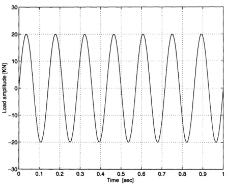
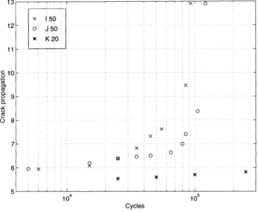
Applied load during fatigue test. The frequency is Crack propagation. ...
condition. .
the base met
7 Hz. ... S. . . 41 . . . . 44 . . .. 46 al. . . 47 . . .. 51 S. .. 51 . . .. 60 . . . . 60 . . .. 62 3-13 Geometry of a plate with width 2b and crack length 2a, under tensile
load . . . .
3-14 Stress intensity factor vs. rate of crack propagation . . . .... 3-15 Stress intensity factor vs. rate of crack propagation ...
4-1 Mechanical properties of the materials used in ADINA ... 2-1 2-2 2-3 2-4 2-5 3-4 3-5 3-6 3-7 3-8 3-9 3-10 3-11 3-12
4-2 Mesh of base metal and soft interlayer. The relative thickness is RT=0.33. 70 4-3 Mesh and nodes on base metal and soft interlayer. The relative
thick-ness is RT=0.33. ... 71
4-4 Stress strain behavior of a joint on HY-100 base metal as a function of the relative thickness of the soft interlayer E8018. . ... . . 73
4-5 Stress strain behavior of a joint on HY-130 base metal as a function of the relative thickness of the soft interlayer E8018. . ... . . 73
4-6 Stress strain behavior of a joint on HY-130 base metal as a function of the relative thickness of the soft interlayer E11018. . ... 74
4-7 Joint tensile strength as a function of the relative thickness of the soft interlayer ... ... 74
4-8 Mesh of the specimen ... 78
4-9 Mesh of the specimen around the notch . ... 79
4-10 Mechanical properties of the materials used in ADINA. . ... 80
4-11 Stress strain behavior of a notched joint on HY-100 base metal as a function of the material of the weldment. . ... 81
4-12 Accumulative effective plastic strain against applied load. ... 81
4-13 Stress strain behavior of a notched joint on HY-130 base metal as a function of the material of the weldment. . ... 82
4-14 Accumulative effective plastic strain against applied load. ... 82
4-15 Mesh of the specimen for the k, calculation . ... 86
4-16 Mesh and nodes of the specimen for the k, calculation ... 87
List of Tables
3.1 Chemical composition of base and weld metals . ... 38
3.2 Carbon equivalent of electrodes ... . . . . 38
3.3 Typical mechanical properties of base and weld metals used in this study 39 3.4 ASW specified mechanical properties of base and weld metals used in this study ... ... 39
3.5 HY-100 welding specimens ... 43
3.6 HY-130 welding specimens ... 43
3.7 Residual stresses at HY-100, caused by the E8018 during the first pass 47 3.8 Residual stresses at HY-100, caused by the E11018 during the first pass 47 3.9 Transverse shrinkage caused by the first pass of welding ... 49
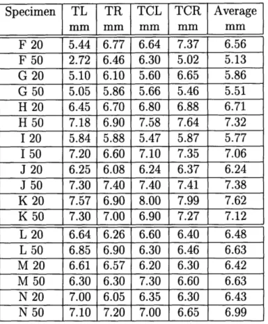
3.10 Crack size on HY-100 and HY-130 specimens . ... 52
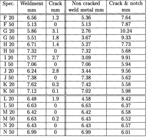
3.11 Average thickness of the weldment on HY-100 and HY-130 specimens 53 3.12 Average size of cracked, and non-cracked weld metal after the last pass 55 3.13 Transverse shrinkage after the first pass . ... 56
3.14 Average transverse shrinkage after the first pass . ... 56
3.15 Crack propagation on I-50 specimen . ... . . . 61
3.16 Crack propagation on J-50 specimen. . ... 61
3.17 Crack propagation on K-20 specimen . ... 61
3.18 Stress intensity factor and rate of crack propagation on I-50 specimen 63 3.19 Stress intensity factor and rate of crack propagation on J-50 specimen 63 3.20 Stress intensity factor and rate of crack propagation on K-20 specimen 63 3.21 Ultimate load and ultimate stress . ... . 66
4.1 Mechanical properties used in ADINA . ... 69 4.2 Joint yield strength and the joint strength elevation of the E8018 weld
metal due to HY-100 base metal ... 75 4.3 Joint yield strength and the joint strength elevation of the E8018 weld
metal due to HY-130 base metal ... 75 4.4 Joint yield strength and the joint strength elevation of the E11018 weld
metal due to HY-130 base metal ... 76 4.5 Comparison of yield strength and the joint strength of 100,
HY-130, E8018 and E11018 alone, under plane strain . ... 76 4.6 Joint yield strength, effective plastic strain and normalized strength of
the joint using the 0.2% offset line . ... . 84 4.7 Ultimate strength of the joint ... . . . . . 84
Chapter 1
Indroduction
Without a doubt, the most important challenge in today's technology is that most structural applications should be designed and constructed having the smallest possi-ble size and weight in order to satisfy the demand for improved efficiency. To achieve this goal many types of high strength steels have been developed and used in numerous applications, such as the construction of warships and submarines.
The performance of these steels has reached an outstanding level not only due to their increased strength, but also due to other improved properties such as ductility and toughness. Welding these steels, however, is not free from problems, which become even more difficult to solve as loading requirements of structures are increased. One of the most serious problems of all is the occurrence of cold cracking. To avoid this phenomenon, these structural steels should be preheated to temperatures that may exceed 1000C. In an actual structure such as a ship, this procedure is extremely
difficult, and results not only in a significant increase of fabrication cost but also in the reduction of productivity.
By using undermatched welds at the root of the bevel, where cracking is most likely to occur, the requirement for preheating can be reduced. This method provides the following advantages:
* the residual stresses at that area are reduced
of the base metal
* the heat of the first pass can serve as a preheating source for subsequent passes applied after a predetermined period of time.
The next passes of welding can be made by an evenmatched weld material, which increases the strength of the joint, shields the soft metal from excessive stresses and plastic deformation, and elevates the strength properties of the soft metal due to the restraint effect.
It has been estimated that the elimination of preheat for HY steels in thickness 0.5" or less can provide savings in excess of one million dollars per ship (1981 dollars). The economic advantages are related to the possible elimination of preheat requirements for weldments, to the relaxed inspection requirements, and to the greater use of higher deposition rates.
Chapter 2
Background
2.1
Past studies on high strength steel welding
Welded joint heterogeneityIn welding high strength steels, it is increasingly difficult to obtain welded joints that match the strength and the toughness of the base metal. This is especially true in the case of quenched and tempered steels, such as HY80, HY100 or HY130, whose strength and fatigue toughness are obtained through heat treatment.
Some reasons for weakness in the welded joints that make them vulnerable to failure are as follows [1, 2]:
* the existence of metallurgical and geometrical defects * the presence of stress raisers
* the deformation level in the vicinity of the crack tip which is mainly controlled by the fracture toughness
* the existence of residual stresses
* the embrittlement in the HAZ and weld metal due to metallurgical changes * and the heterogeneous properties of the material in the joint
The heterogeneity of the material is not only due to the degree of strength mis-matching, but also due to the microstructural changes during the weld thermal cycles. It changes the mechanical properties of the joints, such as yield strength, ultimate strength, strain hardenability, and elongation, affecting both the static ductility test and the the fracture behavior of the welded joints.
Surface cracks and notches can also affect the tensile properties and fracture be-havior of welded structures under tensile stress. They result in concentration of stress and strain, local yielding and development and growth of cracks, which make joints the prime location for fatigue failure. They can also reduce both the tensile strength and the tensile ductility. The strength and ductility reduction become worse by weld undermatching and increased crack size [3].
The most important region in a welded joint is the HAZ because it is the region with the lowest fracture toughness [4], resulting in a large possibility for crack initia-tion. The metallurgical and physical properties of the HAZ depend on the base metal composition, the peak temperature during welding, the heat input and the cooling rate. The latter depends on the plate thickness, preheat and interpass temperatures [5].
Behavior of weld joint due to strength matching
There are two approaches to overcome the problem coming from the heterogeneous properties of the material in the welded joints. One is to accept weld metals that are slightly undermatched in fracture toughness but make certain that they are over-matched in strength. The other approach is to accept weld metals that are slightly undermatched in strength but have adequate fracture toughness.
The first approach prevents strain concentration and subsequent fracture in the weld zone. It has been tested by explosion bulge tests (Masubuchi 1966, Pellini 1976) and has been used by the U.S. Navy in the construction of submarine hulls with HY-80 and HY-100. In the second approach the lower strength of the weld metal may permit a reduction in preheating temperatures. Also, the stress concentration in hard spots can be reduced by allowing local plastic deformation.
In a welded joint loaded perpendicular to the welding direction [2, 5], the acting strain in each cross section is not the same. In an overmatched weld, plastic strains occur essentially in the base metal while the weld metal and the HAZ remain elasti-cally strained, receiving protection against small surface cracks. In the undermatched case the plastic strain accumulation is mainly concentrated in both the weld metal and the HAZ. Due to the strain concentration, at the lower strength weld metal, the driving force of crack propagation increases. To compensate the loss of strength and to allow for high level strain deformation it is essential that the weld metal should have high strain hardening and high fracture toughness [6].
Many investigators believe that the driving force for fracture is inversely propor-tional to the yield strength of the material at the defective region. Since it is extremely
difficult to achieve high toughness level in fabrication welds, undermatching should be avoided and the weld metal overmatching should be ensured in a weldment [5]. Thus weld metal cracks, especially small ones, will be protected from severe plastic strains. However, increased weld metal strength can only be achieved with electrodes having increased alloy content. As the yield strength increases the choice of weld electrodes with adequate toughness becomes limited, and the tendency for weld metal cracking
increases.
The idea of evenmatching or undermatching started recently. It is believed that evenmatching or undermatching can not only provide the benefit of improved tough-ness, but can also reduce the required preheat temperature, improving both the frac-ture performance and the fabrication cost [2]. In most cases the fracfrac-ture toughness is more important than the degree of overmatching, especially when the upper value of the base metal yield strength is not required at the weld metal.
Evaluation of fracture tendency
To evaluate the tendency for fracture, two methods are available. The J-integral and the crack tip opening displacement (CTOD). The J-integral depends on the degree of strength matching and on the crack size [3]. For small cracks in overmatched joints, the J values are significant smaller than those from evenmatched or undermatched joints. Thus overmatched welds shield small cracks from plastic strains. However, large cracks have large J values in all welding conditions.
The fracture toughness of the HAZ can also be evaluated in terms of the crack tip opening displacement (CTOD), which is determined by the local brittle zone. Although the CTOD is similar to the J-integral method, it was proved [4] that the degree of strength matching does not affect the CTOD value at brittle crack initiation obtained by the three-point bent test and the through-thickness notched wide plate tensile tests. The CTOD value in this case is only a function of material toughness at the crack tip. Only in the ductile mode, the degree of strength matching influences the overall performance of welded joints.
strength matching. Although the crack propagates faster in the overmatched case, it propagates toward the base metal. In the evenmatched case it propagates straight forward and in the undermatched case it propagates toward the weld metal [4]. From experiments made by Satoh and Nagai (1969), it was found that the hard interlayer had no effect on the fatigue strength, however the thickness of the soft interlayer affects significantly the fatigue limit. As the thickness of the soft interlayer increases, the fatigue limit decreases drastically.
Eliminating preheating
When welding high strength steels, the risk of cold crack becomes even higher as the degree of restraint of the welding or the yield strength of the base material in-creases. Although modern steels and low hydrogen electrodes have been developed, the cold crack can only be avoided with the use of preheating. According to some investigators [7], the need for preheating can be eliminated with the use of electrodes of low yield strength at the root of the weldment during the first pass. The rest of the bevel is filled with matching electrodes. This method reduces the risk of cold crack initiation and also results in a less expensive technique. It can be used when welding thick constructional steels, high strength steels or during repair welding with severe restraint conditions. The reduction of the preheat temperature depends on the hydrogen content of the electrode and on the base metal carbon equivalent. For hydrogen content less than 3 ml/100 gr, on a 50 mm thick FeE355 steel with CE less than 0.11, no preheat is required, while in many other cases the reduction in the preheat temperature can be approximately 50 to 75 eC.
Similar results were obtained from weld cracking tests on 50 mm, HT80 steel with E11016 and JISD5816 electrodes [8]. The use of an undermatched electrode with lower NTS can prevent root cracking along the fusion line even if the preheat temperature is 25 "C lower than that required at the case of E11016 type electrode, under the same hydrogen level.
.. ... .. r B . . 11A ((A. . . .. I .- I\ A •..\. ... T A I.-, /..- \ [1 3' 31,\. / /! (.I XTh <[ 'AI'
/II
I·
i - -- -/1I//
/ l~ .F'AINI ONGI I IJI'IJAL BUIT W ELIJ I : TRFAN'.VLP'.E BUT I WEtl I
Figure 2-1: Butt welds subjected to tensile loading Behavior of soft welded joints
There are many factors that affect the mechanical behavior of a soft welded joint. Some of those are the type of the joint, the size of the weldment, the degree of strength reduction, the width of the soft inderlayer and the loading direction.
Referring to Figure 2-1, we note that when a tensile load is applied parallel to the welding direction of a butt weld, the joint is under constant strain and the effect of the lower yield strength material is very small as long as the zone has enough ductility. When the applied tensile load is perpendicular to the welding direction, the joint is under constant stress. If the applied stress exceeds the yield strength of the soft zone, strain concentration occurs in the weld metal, resulting in fracture.
However, the strength of a weld metal does not behave as the soft metal itself. It has been confirmed that it is much elevated due to the restraint effect provided by the surrounding stronger metal. From quantitative evaluation of the tensile strength using a model consisting only of the base metal and the soft interlayer (Figure 2-2), it
Figure 2-2: Welded plate including a soft interlayer
resulted that the static strength of welded joints depended upon the relative thickness of the soft interlayer [9, 10]. In the case of a plate, the relative thickness X is the ratio of the width of the interlayer t over the thickness of the plate W. The strength
of the soft interlayer is elevated as the relative thickness X decreases. For X < 1/5
the joint strength becomes almost the same as that of the base metal.
The ductility of the welded joint also depends on the value of the relative thickness X and the ratio k which is the tensile strength of the base metal divided by that of
2.2
High-strength low-alloy quenched and
tem-pered steels
High-strength low-alloy quenched and tempered steels (HSLA Q&T) contain less than 0.25% C and less than 5% alloy. They combine high yield and tensile strength with good ductility, notch toughness, atmospheric corrosion resistance and weldabil-ity. They are strengthened by quenching and tempering to produce microstructures that contain martensite, bainite and in some compositions, ferrite. However, as the strength level of these steels increases they tend to become more difficult to weld with-out crack and other defects. The most common of these steels are HY-80, HY-100 and HY-130.
The HY-80 and HY-100 are quenched and tempered with high strength, good notch toughness and good weldability. Quenching is conducted to avoid the trans-formation of the high temperature austenite phase into undesirable microstructures which are a normal result of the slow cooling. The austenitizing temperature is 900 "C. The quenching medium is water. Tempering involves reheating for one to several hours at 650 "C [11]. HY-80 and HY-100 are made under the specification of MIL-S-16216 and are used principally for naval ships. Welding these steels is not easy since it is extremely difficult to produce weld metal with properties the same as those of the base metal.
The austenitizing temperature of HY-130 is 815 GC, the quenching medium is water and the tempering temperature is 540 oC. The increased strength level of HY-130 makes the welding very difficult. Since it is hard to obtain weld metals having both strength and toughness comparable to those of the base metal, it is essential to use weld wire of a high metallurgical quality and then to protect the weld metal pool by the use of inert gas shielding. As a result the Gas Tungsten Arc method (GTA) is recommended while the shielded metal arc (SMA) should be avoided since it provides poor protection from atmospheric gases.
2.3
Weldability of quenched and tempered steels
Q&T
steels are normally furnished in heat-treated conditions that involve austeni-tizing and quenching and tempering to obtain high strength properties. The HAZ (Heat Affected Zone) of the Q&T steels consists of microstructures of low carbon martensite and bainite. This type of as-welded HAZ microstructure has desirable mechanical properties that are close to those of the base metal. Consequently, these materials generally do not require postweld heat treatment or stress relief treatment. Unlike other hardenable low alloy steels, Q&T steels require a rapid cooling rate in the HAZ to ensure the reformation of martensite and bainite microstructures [11]. A slow HAZ cooling rate must be avoided because it causes the austenitized HAZ to transform into ferrite and a mixture of hard and brittle bainite and martensite. This mixed microstructure of ferrite, bainite and martensite leads to embrittlement of the coarse-grained HAZ. When welding thinner or less hardenable material, an even faster critical cooling rate (less heat input) is required to avoid transformation of brittle mixed microstructure. Limitations on maximum welding heat input for HY 80 and HY 130 are specified in NAVSHIPS 0900-000-1000. For plate thickness less than 0.5 in the maximum allowable heat input should be 45000 joule/in, while for thickness more than 0.5 in the maximum allowable heat input should be 55000 joule/in.Another concern when welding Q&T steels is the strict requirement of low hydro-gen during welding in order to prevent underbead cold cracking. Preheating is one of the most effective ways of reducing the tendency for cold cracking, however it also reduces significantly the cooling rate in the HAZ. Consequently, it should be applied in such a way that a satisfactorily fast cooling rate can be achieved in the HAZ. As the strength level of Q&T steels becomes higher the tendency for hydrogen cracking to occur in the weld metal increases. For steels with yield strength about 690 MPa
(100 ksi) the limit of the moisture content is 0.4% of weight.
The multipass welding can also help avoid regions of high hardness and low tough-ness in the HAZ. The advantages of the multipass welding compared to the single-pass
are that:
* the reheat thermal cycle of each subsequent welding pass normalizes and refines portions of the microstructure in the previous welding pass
* subsequent weld runs temper the previous weld metal and reduce residual stresses from previous runs
* the total energy input is reduced, resulting in a faster cooling rate which is helpful in limiting the amount of grain growth.
Although this method dissipates the hydrogen in the weld metal, it has the dis-advantage of decreased productivity.
2.4
Weldability test
Weldability tests have been developed to evaluate the susceptibility of base and weld metal in cracking. The purpose of these tests is to reduce or eliminate the formation of defects during fabrication.
There are many tests available to evaluate weldability. One of them is the self-restraint test which utilizes the self-restraint or stress within the specimen to cause base or weld metal cracking. The Takken specimen, is a self-restraint test specimen developed in Japan [11, 12]. It is a Y sloped joint which provides more restraint than the U or double U joint. In the test the welding parameters, which are the preheating and the material properties, are varied to alter the stress state. This type of test is used to evaluate HAZ cracking and underbead root cracks.
2.5
Hot and cold cracking
Hot cracks are intergranular and can be found in both the weld metal and the HAZ. They usually occur during the solidification process at the stage where the developed solid crystals restrict the movement of the liquid. Hot cracking can also occur in the HAZ, next to the fusion line due to partial melting of the grain boundaries. In order for theses cracks to form, tensile stresses are required which are provided by the contraction of the weldment during cooling. These cracks are intergranular, small in size and usually remain stable. However, it is possible for them to extend due to hydrogen embrittlement. In that case they become transgranular.
Hot cracking is greatly affected by the chemical composition of both weld and base metal [13]. It can be prevented if S < 0.035%, Ni < 1.0%, Mn > 0.8%, C < 0.15%,
Mn/S > 35, or if HCS < 4, where:
C[S + P + + N1i•]103 (21)
HCS =
3Mn + Cr + Mo+V25 100
Cold cracks are generally transgranular and occur below 200 'C. They initiate during cooling to room temperature, after welding or long after the end of the welding. The hydrogen embrittlement is responsible for cold cracking. The hydrogen results in a decrease of ductility and tensile strength of the specimen. Cold cracking is also known as hydrogen-induced cracking or delayed cracking. It can occur without warning in the HAZ at the weld toe, the weld root or in an underbead position. As the alloy content of the base and weld metal increases cracking can occur in the weld metal.
In order for hydrogen-induced cracking to occur, the following conditions should be present at the same time. Hydrogen should be present, the weld should be under tensile stress, a susceptible microstructure should be present similar to those that exist in the HAZ, and a low temperature should be reached (-100 oC to 200 oC) [14]. Hydrogen cracking can occur without any external loading if high residual stresses are present. As the strength level of the steel increases the weldments become more susceptible to hydrogen cracking.
Hydrogen is produced from many sources such as moisture in the flux of the electrodes. It is absorbed by the weld pool and it is transfered to the HAZ by diffusion. In high strength steels, cracking can occur if the hydrogen content is more than 1 ppm. Cracking is also influenced by the welding heat input and the chemical composition of the base metal. For carbon equivalent (CE) more than 40% underbead cracking is possible to occur. CE is given by:
Mn Ni Cr Cu Mo V
CE = C + + + + (2.2)
6 20 10 40 50 10
To prevent cold cracking when welding high strength steels, low hydrogen elec-trodes should be used. These elecelec-trodes have a very low moisture content, which is the main source of hydrogen. Preheating can also prevent cold cracking by reduc-ing the fast coolreduc-ing that occurs in the HAZ durreduc-ing weldreduc-ing. The reduced coolreduc-ing rate results in softer structure in the HAZ. Also, by keeping the temperature in the HAZ above the critical level for a longer period, the hydrogen diffusion of the HAZ is higher. Therefore the critical concentration of hydrogen at nucleation cites is avoided and the possibility of hydrogen cracking is reduced. As the CE increases, the required preheat temperature to avoid cracking increases. Unfortunately the cooling rate of the HY-100 and HY-130 must be controlled to obtain the required microstructure. Excessive preheat will allow carbides to agglomerate, reducing strength.
By increasing the reaction stresses in a joint, the distortion decreases and cold cracking is more likely to occur. So if we know the CE of the base metal, the hydrogen content of the weld metal, and the intensity of restraint of a joint, the critical cooling time can be determined.
2.6
Residual stresses
Residual stresses are those stresses that exist in a body if all external loads are re-moved. They can result in brittle fracture, fatigue fracture, stress corrosion fracture, cracking and buckling. Residual stresses in welds can be measured by many tech-niques, such as stress relaxation, x-ray diffraction, cracking and techniques that make use of stress sensitive properties. In most of these cases, strain gauges are used to measure strain release. Strain gauges are usually mounted on both surfaces of the plate to study the effect of bending stresses.
In two dimensional plane stress conditions, the fundamental relationships are:
/ I I I I t/ 1 (
EX = e + EX Ey = c + Ey 7Y X y + 7x y (2.3)
Hook's law:
E
(6'
-
)
E
(=
--1
)
G
(2.4)
Equilibrium conditions:
'9Or 'O'rxy 'OTy thy
O9 +
=• 0 ' + =0 (2.5)19X Vy 'Ox 'y
Condition of compatibility:
1P2 6 IVO26 y 1922Y 1926 C 2 92 /1
'
+
)
+
(
+
7x)
= 0
(2.6)
9 +OxOy 19
x2
2y
2'XO
2OXy
In the case of thermal stress: c" = 'y = aAT and "y = 0 where e', e and -y,
II !1 II
are components of elastic strain, E,, y, and -xy are components of plastic strain, a is the coefficient of linear thermal expansion and AT is the change of temperature [13].
Equation 2.6 indicates that in order for residual stresses to exist, the second paren-thesis which contains the non elastic strains should not be zero. The two dimensional plane stress condition is not valid if the plate is over 1" thick, because the residual stresses in the thickness direction become significant and cannot be ignored.
Residual stresses are produced by uneven distribution of non elastic strains such as plastic strains during welding. If a material is heated uniformly, it expands uniformly and thermal stresses are not produced. But during the welding cycle, the weldment is heated locally by the welding heat source. The temperature distribution is not uniform and changes as the welding progresses. This uneven heating produces thermal stresses. After the completion of the welding, high tensile longitudinal stresses a,
exist in regions near the weld, and compressive stresses exist in regions away from the weld. The tensile residual stresses indicate the region where the metal was melted and plastic deformation occurred during the welding thermal cycle. The region with the compressive stresses remains elastic during the entire welding thermal cycle.
The transverse residual stresses ay, are tensile stresses of relatively low magnitude in the middle part of the joint and compressive stresses at the ends of the joints. They are affected significantly by the reaction stresses of the external constraint which are distributed uniformly along the weld. The external constraint has little effect on the
ax residual stresses .
Experimental and analytical results show that the maximum value of the residual stresses on low carbon steels is in the middle of the weld and can be as high as the yield stress of the material (35 to 50 ksi). However, in high strength steel such as HY 130, the residual stresses are widely scattered. Most regions have relatively low tensile stresses (50 to 80 ksi) and only small regions in the center of the weld have high tensile stresses.
From experiments on thermal stresses in weldments of an HY-130 steel, it was concluded that multiple passes produce cumulative plastic strain effects, especially during the first few passes. Little or no accumulation is noted in later passes. It was also observed that the maximum mechanical strain decreases as the base plate yield strength increases.
2.7
Degree of restraint
Residual stresses are closely related to distortion. During the welding cycle, the elastic and plastic thermal strains that are produced in the weld metal and the base metal near the weld, produce internal forces that cause bending, buckling and rotation.
In order to determine analytically the distortion caused by the transverse shrinkage of a restrained weld during the welding cycle, Kihara and Masubuchi [13] developed a formula that gives the degree of restraint on a slit weld type, having a lengthwise straight cut of length L. The geometry of the specimen is shown in Figure 2-3. If the length of the welding 1 covers the whole length of the slit L, 1 = L and F = (1)2. The degree of restraint k, is then:
xEl 2E
2L2F 7rL
Assuming uniform stress ao along the slit, the mean value of the displacement [u] is then:
ao = k, [u]
For given ua as the degree of restraint k, increases the transverse shrinkage decreases. For this type of specimen kI is usually between 60 to 140 kgr/mm2/mm, and the
ratio of the (transverse) shrinkage in a free weld to the shrinkage in a restrained weld is between 0.25 to 0.15.
In a slit weld the degree of restraint k, is not uniform along the length of the slit. Its highest value is at the ends, and as a result the transverse shrinkage is large at the center and very small near the ends.
The major portion of transverse shrinkage of a butt weld is due to the contraction of the base plate. During the welding, the heat of the weld metal is transmitted into the base metal. This causes the base metal to expand. When the weld metal solidifies the expanded base metal starts shrinking. This shrinking is the major part of the transverse shrinkage. The shrinkage of the weld metal is about 10% of the total shrinkage. The longitudinal shrinkage is much less than the transverse shrinkage. An
L
Figure 2-3: Slit type specimen
estimation for the longitudinal shrinkage in butt welds is that AL = 0.001L.
Several techniques have been developed to reduce residual stresses and therefore distortion. The transverse shrinkage can be reduced using larger diameter electrodes, increasing the ks or using an appropriate welding sequence. For example, the block welding causes less shrinkage that the multi layer sequences. Many techniques are also available to relax residual stresses that exist after the end of the welding. One method is the application of a uniform tensile load parallel to the direction of the residual stress. Considering the case of longitudinal stresses in a butt weld, as the external load increases there are certain regions that reach yielding, which in this case is the center of the weldment. The residual stresses that remain after the release of the tensile stress are much smaller and depend on the external load. As the level of applied stress increases, the residual stresses decrease, and become negligible if the applied stress becomes equal to the yield strength of the weld.
In general, the residual stresses affect only those phenomena that occur under a low applied stress, such as brittle fracture and stress corrosion cracking. As the level of applied stress increases, the residual stresses decrease and become negligible if the applied stress increases beyond yielding. Residual stresses and distortion affect very much the buckling phenomenon by significantly reducing the buckling strength of the structure.
2.8
Fracture toughness
Toughness is the ability of the material to absorb energy during fracture. It can be evaluated with impact toughness testing (the Charpy test) and fracture mechanics testing [11].
The Charpy test is used to measure the amount of energy absorbed during fracture of a notched specimen. It is also used to determine the transition temperature at which the material changes its fracture behavior from ductile to brittle mode.
The fracture mechanic testing is used to determine the fracture toughness KIc, which is a material property. The fracture toughness in welding is usually expressed using the crack tip opening displacement.
Types of fracture
The fracture can be either transgranular, which severs the grains, or intergranular which propagate in the grain boundaries. The ductile, brittle and fatigue fracture are transgranular while the stress corrosion cracking, creep fracture and hot tearing are intergranular. Parts failing by ductile fracture (shear mode) are gray and silky, and are characterized by the "equiaxed dimples." Parts failing by brittle fracture (cleavage mode) are bright and granular and in the microscope can be characterized by a "river pattern." The fatigue fracture is characterized by "striations" [13].
Brittle fracture of steels
The appearance of a brittle fracture is granular and the plane of the fracture is perpendicular to the plate surface. The thickness reduction is negligible (less than 3%) even for ductile materials. A brittle fracture requires relatively low temperatures and can happen even if the stresses are well below yielding. The origins in most cases are small defects that cause stress concentration. In steel structures, the fracture usually propagate in the base metal and rarely in the weld metal or HAZ.
The sensitivity of the material to notch brittleness is called notch sensitivity. Notch brittleness is the phenomenon in which steel plate with a sharp notch exhibits
brittle fracture in low temperature. The temperature at which the mode of fracture changes from shear to cleavage is called transition temperature. To avoid brittle frac-ture in a welded strucfrac-ture, the material used should have adequate notch toughness, should not be notch sensitive, and the transition temperature should be lower than the minimum expected temperature during service.
To initiate a crack in a steel plate, the stress should be as high as the yield stress. Even if the applied stress is lower, the existence of a defect can increase the stresses at values close to yield strength, initiating the crack. After this, the crack can propagate at low stress. If the length of the crack becomes longer than the critical length, catastrophic fracture may occur.
One of the most important factors that affect the mechanical properties, such as notch toughness and weldability of steels, is the chemical composition. Elements used in steel manufacturing are C, Mn, Si, P, S, Al, Cr, Ni, Mo. Among those, carbon is the most important alloy. As the content of carbon increases, the ultimate strength and yield strength increases. However the elongation, the notch toughness, and the weldability decreases and the susceptibility to hot and cold cracking increases. The carbon content for a weldable steel should be less than 0.25%
To avoid brittle fracture when welding high strength, quenched and tempered steels, the weld metal should have notch toughness similar to the base metal. However as shown in the following table, this is not possible. The notch toughness requirement of some base metals and electrodes are:
Minimum energy Temperature notes
absorption
HY80, HY100, HY130 60 ft-lb -120 F thickness < 2 in
E8018 C2 20 ft-lb -100 F
E8018 C1 20 ft-lb -75 F
E9018 M, E10018 M, 20 ft-lb -60 F
E11018 M, E12018 M
As the yield strength of the material of the base plate increases, high quality welding processes such as GTA and GMA should be used.
2.9
Fracture mechanics theory
In the fracture mechanics theory there are three types of cracking modes. The opening mode (mode I) which is caused by stress normal to the plane of the crack, the sliding mode (mode II) which is caused by in-plane shear stresses and the tearing mode (mode III) which is caused by out of plane stresses. Although all three modes of cracks exist in a general case, the mode I is the most important.
The stresses around the tip of a mode I crack with length 2a, in an infinite plate, under uniform tensile stress a are:
K 0 0 390
oa = K cos -(1 + sin - sin -)
v1
- 2 2 2
K 0 0 30
X
=
cos (1 - sin sin2 ) (2.8)K . 9 9 39
TX -
V/Z27r
sin
- cos -
2
2 2
cos
)
K = Ouavl (2.9) where K is the stress intensity factor, and
/
depends on the geometry and the location of the crack. If 2a is much smaller than the plate width w,P
0 1. As 2a increases/
increases and finally for 2a = w, ) = 4. Along the x axis and for 0 = 0K
O'y = Orx -- 2/ and TXy =
0
Fracture will occur as K reaches the critical value Kc which is called "critical stress intensity factor" or "fracture toughness." The Kc depends on the material but also on the state of stress applied at the crack tip. For the plane strain case, the Kc
gets its lower value KIc which can be considered as a material constant. To obtain plane strain state of stress around a crack tip, the thickness of the plate should be
B > 2.5(K'c)2 [15]. The K1C value of different steels decreases drastically as the yield strength of the material increases.
--- -- ---- .... .
Figure 2-4: Fracture toughness against thickness. by the crack opening displacement (COD):
COD = a - x2 (2.10)
E
where at x = 0 is the center of the crack and at x = a is the tip of the crack. At x = a the crack tip opening displacement (CTOD) is given by:
CTOD = K(1 - (2.11)
or for the case of plane stress:
K2
CTOD = (2.12)
E. Aays
where A - - 1. Also at x = 0 the COD is:
COD = a2 +(2.13)
E 16ox2(CTOD)2
Although a brittle fracture requires that the length of the crack should be larger than the critical length, it has been observed that brittle fracture can occur at cracks having smaller size. This can happen if there is enough energy from residual stresses during fatigue or under stress corrosion cracking.
Equation 2.11 can be used to determine the KIc from a CTOD measurement on a small, three-point bent specimen with small crack.
2.10
Fatigue fracture
Under a given value of maximum applied stress, the material will fracture after a number of cycles. If the applied load is lower, more number of cycles are required for fracture. In some materials, and especially ferrous metals, the life of the structure becomes infinite if the stress is equal or less to a certain value. This value is called endurance limit. It is affected by the material strength, the stress concentration and the environment. As the material strength increases, the endurance increases by a factor of 0.5. The endurance limit is affected by the surface polishing. Cracks, notches and discontinuities such as weld reinforcement cause stress concentration which reduce the fatigue life of the structure.
There are two types of fatigue. The low cycle and the high cycle. A high cycle fatigue requires more than 105 cycles and the deformations of the metal are within the elastic region. A low cycle fatigue requires less than 105 cycles and the applied
stress is above yielding.
During a fatigue test the effect of the residual stresses is not always important. As a repeated load is applied, not only the magnitude but also the direction of the stress distribution around the crack changes. For example the high tensile stresses at the tip of a crack can become compressive after a tensile load has been applied once. When this load is released, the whole specimen unloads elastically leaving compressive stresses at the tips. The magnitude of the compressive stresses depend on the tensile load. A repeated alternative load of the same magnitude will cause changes on the stresses around the crack but the stresses will remain compressive.
During the service life of a structure, a defect or a flaw may form a small crack. The crack usually initiates from the surface of the specimen; it is much smaller than the critical length and cannot cause fracture. However, it can grow until it reaches the critical size. At that time catastrophic fracture will occur.
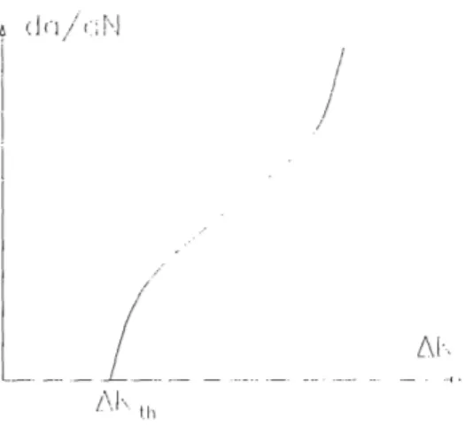
As the crack grows the stress intensity factor K increases. During a fatigue cycle
/
!L
Figure 2-5: Rate of fatigue crack propagation against range of stress intensity factor. propagation per cycle - is a function of the AK = Kma - Kmin.
da
= C(AK)" (2.14)
dN
where C and n are constants, Smax is the maximum applied stress, Smin is the mini-mum applied stress, Sm = smpzSmi is the mean stress and S, = Sma, - Smi, is the stress range.
Fatigue crack starts to grow when AK reaches a threshold value AKth (Figure 2-5). The lower part of the curve represents the initiation of the crack, the middle part the stable crack growth, and the upper part the unstable fracture. Total fracture occurs during the cycle where the stress intensity reaches KIc [15].
Chapter 3
Experimental Description and
Results
3.1
Steel properties and electrode selection
The materials used as base metals in this study were the high strength low alloy quenched and tempered steels (HSLA Q&T) HY-100 and HY-130. The consumables were selected according to the required degree of strength mismatch, the need for electrodes with the smallest possible value of carbon equivalent (CE), and the avail-ability of those electrodes in the market. The electrodes that have the required degree of strength matching are the E80XX and the E11OXX.
Carbon equivalent
The maximum and minimum values of the chemical composition for the 100, HY-130 and electrodes are shown in Table 3.1 [11, 16]. When only one value is shown, it is the maximum value.
The CE for each material was calculated using the following formula:
Mn Ni Cr Cu Mo V CE = C + + + +
6 20 10 40 50 10
For each electrode two values were calculated. One based on the average value of chemical composition and one based on the minimum values from Table 3.1.
The electrodes with the smallest carbon equivalent value were the E8018 C3, the E11018 M and the E8018 B2L. The carbon equivalent of each electrode appears in Table 3.2. Although the E8018 C3 provides better resistance to hydrogen induced cracking, the E8018 B2L was used instead.
Degree of strength mismatch
Typical mechanical properties of the materials used and the ASW specifications of those materials are shown in Tables 3.3 and 3.4. By combining these materials we can obtain joints with different degrees of strength matching. The degree of strength
matching of each joint is given by
DM = UYS(weld) - UYS(plate)
UYS(plate)
The E11018 M results in evenmatching and the E8018 in a 20% strength under-matching at the HY-100 base metal. The E11018 and the E8018 cause 40% and 25% undermatching at the HY-130 respectively.
Tensile test of base metals
To verify the properties of the HY-100 and HY-130, a tensile test was performed. A round tensile specimen was made from the plate of each material (Figure 3-3). The total length was 180 mm, the middle section length was 44 mm (1.7") and the middle section diameter was 5.08 mm (0.2").
The yield strength at 0.2% offset of the HY-100 was 724 MPa (105 ksi), the ultimate strength was 806.7 MPa (117 ksi) and the modulus of elasticity was 227.5 GPa (33 E03 ksi).
The HY-130 had both yield strength (0.2% offset) and ultimate strength at 986.0 MPa (143 ksi). The modulus of elasticity was 213.7 GPa (31 E03 ksi). Results from the tensile tests appear in Figure 3-1 and 3-2.
Plane strain effect
To evaluate the stress required to cause yielding of a homogeneous material, the plate shown in Figure 3-4 is examined analytically [17, 18]. The plate is loaded along the xl direction with the stress al. The width W of the plate is much larger than the thickness of the plate t, so it can be assumed that the plate is under plane strain condition. Consequently 63 = 0 and:
E3 = E I3 - V(O2 + -rl)) = 0 - O3 = 1/v( 2 + 01)
Substituting in the Von Mises yield criterion:
(aO" - a2)2 ( 2 - 2 + () 3 - a1)2 = 242
which concludes that in order to bring the material at yield condition:
2 Y
1 - 1 - v + v2
For steels v = 0.3 so:
al = 1.125ay
The yield strength of the material under plane strain is about 10% elevated from its original value, due to the restraint effect caused by the plane stress condition.
HY130 HY100 E11018M E8018C3 E8018B2L C 0.12 0.12-0.20 0.1 0.12 0.1 Mn 0.60-0.90 0.10-0.40 1.30-1.8 0.40-1.1 1.3-1.8 P 0.01 0.025 0.03 0.03 0.03 S 0.015 0.025 0.03 0.03 0.03 Si 0.15-0.35 0.15-0.35 0.6 0.8 0.6 Cr 0.4-0.7 1.0-1.8 0.4 0.15 0.4 Ni 4.75-5.25 2.25-3.5 1.25-2.5 0.8-1.1 1.25-2.5 Mo 0.30-0.65 0.20-0.6 0.30-0.55 0.35 0.25-0.5 Cu 0.25 V 0.05-0.10 0.03 0.05 0.05 0.05 Ti 0.02
Table 3.1: Chemical composition of base and weld metals
Electrode average CE minimum CE
E11018 M 0.5770 0.4832
E8018/16 C3 0.2955 0.2297
E8018 B2L 0.4771 0.4092
J
HY100
HY130
E8018B2L
IE11018M
yield stress 724.0 MPa 944.6 MPa 573.6 MPa 703.3 MPa (0.2% offset) 105 ksi 137 ksi 83.2 ksi 102.3 ksi ultimate strength 813.6 MPa 986.0 MPa 673.6 MPa 774.3 MPa
118 ksi 143 ksi 97.7 ksi 112.3 ksi
elongation % in 2" 24 22
area reduction 72.6 63
charpy V notch -20 F 46 ft lbs
-40 F 30 ft lbs
-60 F 65 ft lbs
Table 3.3: Typical mechanical properties of base and weld metals used in this study
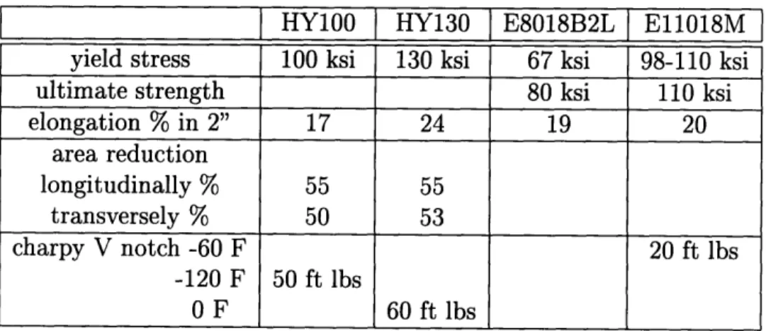
HY100 HY130 E8018B2L E11018M
yield stress 100 ksi 130 ksi 67 ksi 98-110 ksi
ultimate strength 80 ksi 110 ksi
elongation % in 2" 17 24 19 20 area reduction longitudinally % 55 55 transversely % 50 53 charpy V notch -60 F 20 ft lbs -120 F 50 ft lbs 0 F 60 ft lbs
Table 3.4: ASW specified mechanical properties of base and weld metals used in this study
strain
Figure 3-1: Stress strain curve from tensile test of the HY-100.
0 0.02 0.04 0.06 0.08 0.1 0.12 0.14
strain
Figure 3-2: Stress strain curve from tensile test of the HY-130.
v,9 II. ·--L
I - 1 1
Figure 3-3: Base metal specimen for the tensile test.
.... . ...
T~ 1
Figure 3-4: Plate subjected to tensile stress under plane strain condition.
r::j !ii ::i I ' l l '
I i'"l i" I·, ! I"1·
·-3.2
Experimental results
The test methods used for the experimental evaluation of the strength of welded joint, were the self restraint crack test, the fatigue test, and the tensile test. The self restraint crack test was performed on HY-100 and HY-130, U.S. Navy Q&T steel specimens, welded by E8018 B2L and E11018 M electrodes.
After the welding of the first and last pass, and during the fatigue test, the spec-imens were observed for cracks using an optical and a helium-neon confocal laser microscope [19].
3.2.1
Self-restraint cracking test
The restraint crack test was performed to observe the effects of joint strength matching on HY-100 and HY-130 high strength steels.
During the restraint crack test, two parameters were investigated. The first pa-rameter was the strength of the weld metal. Each base metal was welded with the two available electrodes to form different degrees of strength mismatch. Welding was performed in three passes. The second and the third passes were made with the same electrode, which was not necessarily the same as the first pass. The second parameter was the preheat temperature. Before the welding, the plates were preheated at either 20 'C or 50 'C. The preheating was done with a gas flame.
The combinations that were performed among steels plates, electrodes, and pre-heat temperatures are shown in Table 3.5 and 3.6. The electrode diameter was 2.6 mm. All the electrodes were in sealed tins and they were baked for more than an hour just before welding.
The F and I specimens represent 20% strength undermatching and the H and K represent evenmatching. The G and J represent the application of undermatching in the root pass of the weldment, while the rest of the groove was filled with evenmatched electrode. At the HY-130 the L specimens represent 40% undermatching, the M represent undermatching with softer material at the root pass of the weldment, and the N represent 25% undermatching.
Specimen Preheating first pass next passes F 20 200C E8018 E8018 F 50 500C E8018 E8018 G 20 200C E8018 E11018 G 50 500C E8018 E11018 H 20 200C E11018 E11018 H 50 500C E11018 E11018 I 20 200C E8018 E8018 I 50 500C E8018 E8018 J 20 200C E8018 E11018 J 50 500C E8018 E11018 K 20 200C E11018 E11018 K 50 500C E11018 E11018
Table 3.5: HY-100 welding specimens
Specimen Preheating first pass next passes
L 20 200C E8018 E8018 L 50 500C E8018 E8018 M 20 200C E8018 E11018 M 50 500C E8018 E11018 N 20 200C E11018 E11018 N 50 500C E11018 E11018
r
· · ;'''
II.I
i
II
Figure 3-5: Geometry of the specimens. Welding conditions
The welding process used for the welding was the Shielded Metal Arc welding (SMA). The welding voltage was E = 36 Volts, the current was I = 100 Amperes and the welding speed was S = 4mm/sec = lOin/min. The heat input is given by the
formula:
E I 60
H = = 23KJ/in
S -1000
From reference [11] (page 667, Table 7), the maximum allowed heat input for 12.7 mm plate thickness and preheat temperature 200C is 70 KJ/in, while for preheat temperature 5000C is 65 KJ/in.
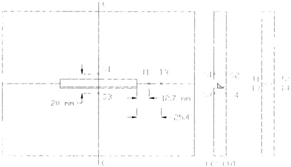
Test specimen description
The shape of the restraint cracking specimen is shown in Figure 3-5. The thickness of the plate was 13 mm. The notch was 1 mm thick and the angle of the groove was 45".
To construct the specimen, the plate in Figure 3-5 was cut along the DD' line. After the fabrication of the 1 mm notch and the 450 groove, the two pieces were welded together along the same line to form the original specimen.
f
II;
i i_
The degree of restraint for that geometry can be calculated using equation 2.7.
2E
S-rL
For E = 207GPa and L = 0.08m the degree of restraint is
ks = 1.647E12N 2 = 168kg/mm2
m mm
According to Masubuchi [13] the expected value for a slit type specimen is
k, = 60 to 140 kg/mm2
mm
As a result, the transverse shrinkage is expected to be small, resulting in a high cracking possibility.
Experimental procedure
The restraint crack test was performed by welding the first pass under the conditions shown in Table 3.5 and 3.6. Twenty-four hours after the end of the first pass, the residual stresses and the transverse shrinkage of the plate were measured. The spec-imen was then cut along the CC' line for crack observation. After the observation, the two parts were clamped together to form the original specimen and to perform the remaining passes of the welding. When the specimens were cooled down, they were cut again along the CC', LL' and RR' line (Figure 3-8) for crack observation.
Residual stresses results
The residual stresses perpendicular to the welding direction were measured using strain gauges at two HY-100 specimens, the F20 and the H20. The strain gauges were placed at the points T1 and T3 on the upper surface of the specimen, and T2 and T4 on the lower surface. The location of these points appears in Figure 3-6. The strain gauges were placed on the base metal to prevent the welding heat from damaging them. The residual stresses at the top and bottom surfaces were averaged
I i
1 7,
I II
I I:
i ri
Figure 3-6: Restraint cracking specimen. to avoid the influence of bending.
The strain gauge output voltage was measured before and after the welding of the first pass. The difference of those measurements was converted into strain using the gauge conversion factor. The conversion factor of the strain gauges is 2.09E06 V- 1 Assuming only elastic strain in that region of the base plate, the residual stresses in a direction perpendicular to the welding direction were obtained by multiplying the measured strains with the modulus of elasticity.
The detailed results appear in Tables 3.7 and 3.8. An estimation of the transverse residual stress distribution in the base metal, along the welding direction, is shown in Fig 3-7. From the results it is obvious that the residual stresses of undermatched welds are lower than those caused by evenmatched welds, reducing the potential of crack initiation.
.I I
--units strain gages 1,2 strain gages 3,4 Initial strain Volts 278.3030 E-06 91.7057 E-06 After 1st pass Volts -437.4000 E-06 -329.2670 E-06 Residual strain Volts -715.703 E-06 -420.9727 E-06 Residual strain c -1495.8193 E-06 -879.8329 E-06 Residual stress -31.4122 kg/mm2 -18.4765 kg/mm 2
Table 3.7: Residual stresses at HY-100, caused by the E8018 during the first pass
units strain gages 1,2 strain gages 3,4 Initial strain Volts 576.657 E-06 -179.673 E-06 After 1st pass Volts -347.3870 E-06 -397.137 E-06 Residual strain Volts -924.044 E-06 -217.464 E-06 Residual strain e -1931.252 E-06 -454.4998 E-06 Residual stress -40.5563 kg/mm 2 -9.5445 kg/mm2
Table 3.8: Residual stresses at HY-100, caused by the E11018 during the first pass
,. r-/ J n I_ r F', g r/ mrnr 3C) H)'--100 & £11018 '.. .100 -! K8 '"018 F -... . . -MF I T I 0 % .) 10 ..• I( [ - C