HAL Id: hal-02442254
https://hal-cea.archives-ouvertes.fr/hal-02442254
Submitted on 16 Jan 2020
HAL is a multi-disciplinary open access archive for the deposit and dissemination of sci-entific research documents, whether they are pub-lished or not. The documents may come from teaching and research institutions in France or abroad, or from public or private research centers.
L’archive ouverte pluridisciplinaire HAL, est destinée au dépôt et à la diffusion de documents scientifiques de niveau recherche, publiés ou non, émanant des établissements d’enseignement et de recherche français ou étrangers, des laboratoires publics ou privés.
Progress in Electrofiltration for Gaz Cleaning
F. Lemont, M. Marchand, Thierry Reess, Antoine Silvestre de Ferron, S.
Souakri
To cite this version:
F. Lemont, M. Marchand, Thierry Reess, Antoine Silvestre de Ferron, S. Souakri. Progress in Elec-trofiltration for Gaz Cleaning. WasteEng2016, May 2016, Albi, France. �hal-02442254�
I. INTRODUCTION
New chemical processes for waste treatment and conditioning are under development in the nuclear industry. The processes developed by the CEA's LPIC laboratory involve a stage during which the waste organic material is incinerated, followed by a phase of processing the mineral ash obtained (concentration, separation, and packaging in a vitreous matrix). These steps generate combustion gases loaded with dust that it is essential to filter into the centralized system for processing gases downstream of the cycle. The most conventional technology used in the nuclear industry to purify loaded gases is filtration through porous media. These filters are highly efficient but they have two major drawbacks. First, the porous media generate additional secondary radioactive waste during the nuclear operation. Secondly, their progressive dust loading causes depression drop in the process which affects the design basis of the ventilation systems.
Research is currently being carried out at the CEA on others filtration technologies such as electrostatic precipitation. These systems overcome the two main operating constraints
related to the use of conventional porous media filters. However, before considering incorporating such systems in nuclear facilities, technological developments must be demonstrated to improve the filtration performance of these devices during representative operating periods.
II. METHODOLOGY
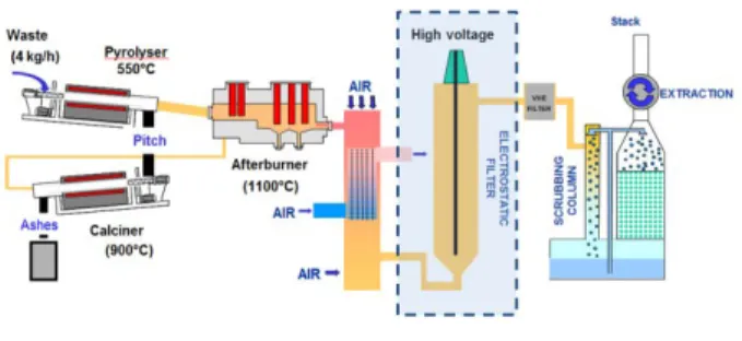
The results presented in this paper were obtained from an electrostatic precipitator built into the CEA Marcoule's IRIS process gas treatment unit (see Fig. 1).
Fig. 1. CEA's IRIS process with its electrostatic precipitator.
The IRIS process gas treatment consists of a
Progress in Electrofiltration for Gaz Cleaning
F. Lemont1,M.Marchand, T. Reess2, A. Silvestre de Ferron2, S. Souakri2 1 DEN, DTCD, LPIC, CEA Marcoule, F-30207 Bagnols-sur-Cèze Cedex, France
2 SIAME, Université de Pau, 2 avenue Angot, 64000 Pau, France
Abstract— Industrial thermal processes generate a large amount of gases to be treated before released to atmosphere. Filtration is one of the major steps of this treatment as it ensures no release of solid particles. In any given field, electrostatic precipitators are technologies of choice because of several reasons: they avoid significant pressure drop in industrial systems; they do not need any filtering media; they may have simple geometry; their cleaning is easy; … These reasons explain why this technology is particularly attractive when the thermal treatment is applied to radioactive material and then why the CEA works for several years to improve electrostatic precipitation applied to its needs. The main objective of the research and development performed in this field was to increase the filtering efficiency of the filters together with their endurance. After more than ten years of work, objective has been broadly reached and can be applied to various applications, nuclear or not.
The major purpose of the present paper is to explain the different steps of research that have led to pass from a few tens of minutes of optimal efficiency up to several hours. Electrode geometry, electrostatic field modeling, high-voltage direct and pulsed current, sonic and ultrasonic cleaning … were at the heart of these developments and have led to very conclusive results.
Keywords— electrostatic, filtration, electrode, dust, high voltage, pulsed
Corresponding author: Marchand Mickael e-mail address: [email protected]
cooler, an electrostatic precipitator, two HEPA filters in parallel as well as a scrubber. First, combustion gases loaded with dust are cooled with an air/air heat exchanger. The heat exchanger output gases have an average temperature of 130°C and are loaded with dust with a concentration around 3.106 particles per litre. Then gases flow into an electrostatic precipitator. The electrostatic precipitator had been designed beforehand from the Deutsch equation defined by
η=1−e(−WS/Q) (1) in which η represents collection efficiency,
W velocity of the particles, S particle
collection surface area and Q gas flow rate. For dust collection target efficiency of 99.75%, the dust collection surface area S is 3.8 m2 with the
following process variables: gas flow rate Q of 480 m3/h and particle velocity W of 0.2 m/s.
Consequently, the IRIS process electrostatic precipitator consists of a 4-meter-long stainless steel cylindrical shell with an internal diameter of 350 mm and a central emission electrode bearing a negative potential. The inner wall of the shell, which forms the other electrode, is grounded. An electric field is then set up between both electrodes. This field charges the dust contained in the gases and then they migrate to the collecting electrode. For this study, filtration effectiveness was measured using two isokinetic sampling sensors placed upstream and downstream the precipitator. These both sensors include a flowmeter to modulate the shielding gas and also a paper filter weighed before and after testing to measure the amount of dust collected and thus make filtration performance available.
Different geometries of emissive electrodes may influence the gas ionisation process by boosting the value of the electric field in its vicinity [1]. To improve the performance of the IRIS electrostatic precipitator, an experimental study to geometrically optimise the emitting electrode was conducted to obtain a maximum ionisation field while taking care to remain under the critical threshold of breakdown in the air (5 kV.cm-1 positive and 13 kV.cm-1 negative
[2]). The various configurations were assessed by measuring the negative direct power supply voltage applied to the central filtration electrode and the resulting average current. Particle collection effectiveness was also measured according to filtration time. These tests were initially conducted using the electrostatic precipitator operating in air and then operating with dust from the process.
III. RESULTS
A. Presentation of the various geometries of filtration electrodes
Six different geometries of central electrodes were tested (Fig. 2). The first geometry (a) consists of a tungsten wire with a weight at one end to limit its movement inside the precipitator. The second (b) and third (c) configurations tested are normal and studded steel rods having a diameter of 5 and 6 mm, respectively. The fourth (d) geometry is a threaded rod with an outer diameter of 10 mm. Finally, the fifth geometry (e) is a steel tube of 25 mm in diameter with emissive pattern created.
Fig. 2. View of the five central filtration electrode geometries tested in the IRIS process electrostatic
precipitator.
B. Influence of the geometry on the power supply voltage and current
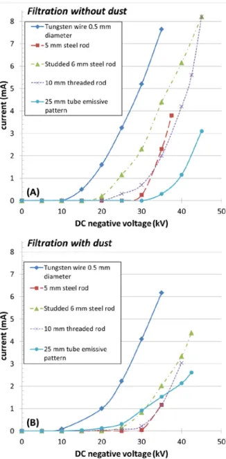
Fig. 3 shows the change in the measured average current (in mA) depending on the voltage (in kV) applied to each of the electrodes during electrostatic precipitator operating in air (Fig 3A) then with the dust load from the process (Fig 3B). These measurements were obtained using a TECHNIX power source SR80-N-5 kW.
Fig. 3. Change in the average current measured according to the direct voltage applied for five geometric
configurations of electrodes at T=130°C.
The results show different behaviors according to the atmosphere and chosen geometry. One one hand, in presence of particles (Fig. 3B), the use of a tungsten wire results in the higher currents (up to 6.2 mA) with a maximum allowable voltage of -35 kV before a spark is produced. On the other hand, with the 25 mm tube emissive pattern, maximum voltages are greater (up to -43 kV) but maximum currents are weaker (2.6 mA).
Tungsten is a ductile material that becomes rough on the surface when it is stretched to its limits. This property has been used with the tungsten wire to generate a significant amount
of emissive patterns on a microscopic scale and thus set up a higher average current. Conversely, for the studded tungsten tube, there are fewer emissive patterns (and therefore the average current recorded is lower). However the geometry of the tube leads to apply a higher power supply voltage in relation to the tungsten wire because the field amplification factor is lower.
TABLE 1
COMPARISON OF FILTRATION EFFICIENCIES OBTAINED FROM DIFFERENT ELECTRODES
GEOMETRIES.
C. Measuring filtration efficiency
Table 1 summarises filtration performance for a voltage and a given current from different geometric configurations. Filtering performance was calculated by measuring the mass of dust on a paper filter from two isokinetic sampling probes located upstream and downstream of the electrostatic precipitator using the following relationship: in out m m − =1 η (2) where m and in moutare respectively the masses of dust deposited on the paper filter at the input and output of the two sampling probes. The best filtration efficiencies were obtained with the tungsten wire (98.7%) then with the rod (98.1%) and finally with the 25 mm steel tube (97.8%) respectively. We noted that for a fixed voltage of -40 kV, the 25 mm steel tube presents 1% less efficiency than the tungsten wire. Consequently, the tube seems less efficient than the tungsten wire, but it has a markedly better mechanical strength when it is placed in the shielding gas inside the electrostatic precipitator because it does not
move around the central axis of the electrostatic precipitator, particularly in the event of major disturbance induced by the modulation of process gas flowrates. This geometric configuration has therefore been retained for further studies because this avoids having to put centering devices inside the precipitator which facilitate the routing of arcs.
Fig. 4. Change in dust collection efficiency as function of time using the 25 mm steel tube.
D. Change in filtration efficiency as a function of time
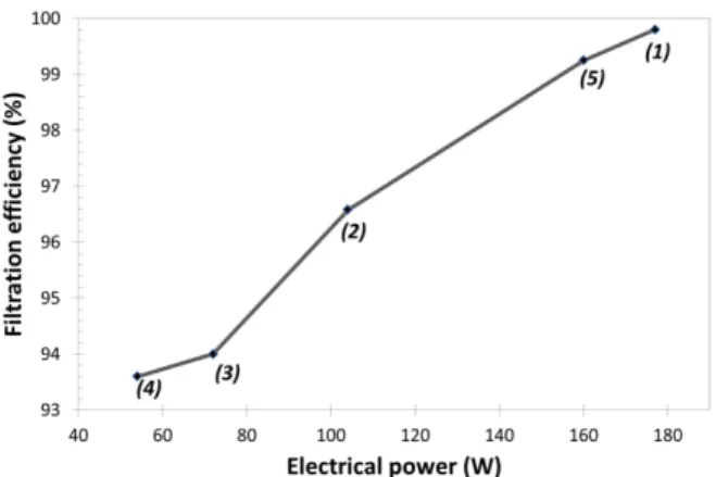
Fig. 4 and 5 represent the change in dust collection efficiency according to the filtering time and imposed electrical power respectively. The 25 mm steel tube was used for this study. Five successive measurements (points 1 to 5) were taken. By comparing both curves simultaneously, we can see that for a fixed voltage of -67 kV, the filtration performance decreases from 99.8% at time t = 0 (point 1) to a value close to 93.5% after more than 5 hours of testing (point 4). At the same time, the electrical power decreases from 175 W (i.e. I = 2.6 mA for point 1) to a value of 55 W (i.e. I = 0.82 mA for point 4) after a 5 hours filtration time (Figure 5).
Fig. 5. Change in filtration efficiency in relation to the imposed electrical power.
It is therefore shown that dust filtration efficiency decreases with time, as already observed with a point-to-plane configuration [3]. The decrease of the average current is due to the fact that more and more particles settle on the (grounded) collecting electrode, resulting in a reduction of the electric field by accumulation of negative charges on the electrode, as dusts are non-conductive. In order to maintain optimum efficiency, the power supply voltage has been increased to a value of -80 kV (point 5) which had the immediate effect of achieving dust filtration efficiency close to 99.5% for an electrical power of 160 W. Adjusting the power by increasing the power supply voltage therefore obtains values close to the initial conditions (point 1) without, nevertheless, achieving them. To obtain exactly the same initial conditions, all the dust deposited inside the electrostatic precipitator has to be removed. This manipulation is restrictive in the context of industrial operation.
IV. DISCUSSION
The results show that filtration efficiency can be improved by optimising the geometry of the central electrode. The main aim is to generate a maximum electrostatic field between both electrodes to facilitate the migration of dust particles. It has been shown that filtration efficiency is then dependent on the average current measured but decreases with time [3]. To maintain a good level of filtration, it is then mandatory to continually increase the power supply voltage applied to the central filtration electrode. This voltage increase must not reach
a maximum value that causes filamentary discharge to appear inside the electrostatic precipitator and the emergence of "back corona" type phenomena [4].
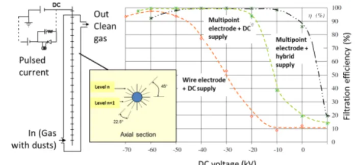
Fig. 6. Axial section of the new multi-point electrode and comparison of filtration efficiency in relation to two
other electrode geometries.
Specific electrode geometry combined with a pulsed power system has therefore been developed to optimise the effectiveness of particle collection over long periods of time. Studies carried out in collaboration with the University of Pau SIAME laboratory helped recommend a new electrode called "multi-point" along with an optimised power supply [5]. The multi-point electrode consists of a 2-meter-long rod comprising a set of points spaced at an angle of 45° on the same plane and offset at an angle of 22.5° between two successive levels (see inset Fig. 6).
The filtration efficiency obtained from this new multi-point electrode has been improved as shown by the results presented in Fig. 6. By comparing the efficiency curve with the two other geometries (wire electrode and multipoint electrode), a filtration efficiency greater than 99.7% can be achieved from -30 kV up to -95 kV (see the new multi-point electrode curve on Fig. 6). The efficiency is then optimal on a wider voltage range by increasing the maximum value of the voltage (-95 kV) without apparition of filamentary discharge. Furthermore, by combining this new multi-point electrode with a mixed direct/alternating power supply, filtration performance over long periods can be significantly improved. Filtration efficiency, with this new configuration, does not decrease even after
more than 500 minutes of electrostatic precipitator operation (Fig. 7). These values are obtained only if this multi-point electrode is combined with a mixed direct/alternating power source. Results show that, with a direct power supply alone, effectiveness begins to drop after 200 minutes of electrostatic precipitator operation.
Fig. 7. Comparison of filtration efficiency as a factor of time for two electrodes (shaped rod and multi-point rod)
using direct or direct/alternating power supply. V. CONCLUSION
Different geometries of emitting electrodes have been tested to compare the filtration efficiency of an electrostatic precipitator according to the applied voltage and average current. The filtering performance of these electrodes was then assessed as a factor of time. The results obtained were used to develop a new geometry of electrode called "multi-point". This new configuration helped improve filtration efficiency over a wider voltage range. The use of a combined direct/alternating power source on this multi-point electrode significantly improved the performance of the electrostatic precipitator over long periods of operation.
REFERENCES
[1] D. Blanchard, “Collecte des fines particules et
caractérisation des couches de poussière dans un précipitateur électrostatique”, Thesis, Université Joseph Fourier, Grenoble, 2001.
[2] S. Gaychet, “Modélisation des décharges couronnes
négatives – Application à la précipitation électrostatique”, Thesis, Université de Pau, Pau, 2010.
[3] A. Silvestre de Ferron, T. Reess, L. Pecastaing, P. Pignolet and F. Lemont, “Optimizing the operation of an electrostatic precipitator by developing a multipoint electrode supplied by a hybrid generator”, J. Phys. D: Appl. Phys., 42, 105504, 2009.
[4] P. Ranstad, A. Karlsson, C. Tonks and K. Bradburn, “Results from ESP-upgrades, including control systems”, Proceedings ICESP, 2013.
[5] F. Lemont, A. Silvestre de Ferron, T. Reess, A. Russelo, “Device for electrostatic filtering using optimised emissive sites” Patent WO 2009103704 A2, 2009