HAL Id: tel-00931001
https://tel.archives-ouvertes.fr/tel-00931001v2
Submitted on 7 Apr 2014HAL is a multi-disciplinary open access archive for the deposit and dissemination of sci-entific research documents, whether they are pub-lished or not. The documents may come from teaching and research institutions in France or abroad, or from public or private research centers.
L’archive ouverte pluridisciplinaire HAL, est destinée au dépôt et à la diffusion de documents scientifiques de niveau recherche, publiés ou non, émanant des établissements d’enseignement et de recherche français ou étrangers, des laboratoires publics ou privés.
Modeling functional and non-functional properties of
systems based on a multi-view approach
Carlos Ernesto Gómez Cárdenas
To cite this version:
Carlos Ernesto Gómez Cárdenas. Modeling functional and non-functional properties of systems based on a multi-view approach. Other [cs.OH]. Université Nice Sophia Antipolis, 2013. English. �NNT : 2013NICE4153�. �tel-00931001v2�
UNIVERSITÉ NICE - SOPHIA ANTIPOLIS
ÉCOLE DOCTORALE STIC
SCIENCES ET TECHNOLOGIES DE L’INFORMATION ET DE LA COMMUNICATION
T H È S E
pour l’obtention du grade de
Docteur en Sciences
de l’Université Nice - Sophia Antipolis
Mention : Informatique
presentée et soutenue par
Carlos Ernesto
Gómez Cárdenas
Une approche multi-vue pour la
modélisation système de
propriétés fonctionnelles et
non-fonctionnelles
Modeling Functional and Non-Functional Properties of
Systems Based on A Multi-View Approach
Thèse dirigée par: Frédéric Mallet
et encadrée par: Julien DeAntoni
soutenue le 20 décembre 2013 Jury :
M. Frédéric Boulanger Prof. SUPÉLEC Rapporteur M. Abdoulaye Gamatié C.R. LIRMM-CNRS Rapporteur
M. Michel Auguin D.R. LEAT-CNRS Examinateur
M. Jean-Philippe Diguet D.R. LabSTICC-CNRS Examinateur M. Frédéric Mallet M.C. INRIA/I3S-CNRS Directeur de Thèse M. Julien DeAntoni M.C. INRIA/I3S-CNRS Encadrant
“Il y a des hommes qui luttent un jour et qui sont bons. Il y en a d’autres qui luttent un an et qui sont meilleurs. Il y en a qui luttent pendant des années et qui sont excellents.
Mais il y en a qui luttent toute leur vie et ceux-là sont indispensables.”
“There are men who struggle for a day and they are good. There are men who struggle for a year and they are better. There are men who struggle many years, and they are better still. But there are those who struggle all their lives:
These are the indispensable ones.”
“Hay hombres que luchan un día y son buenos. Hay otros que luchan un año y son mejores.
Hay quienes luchan muchos años y son muy buenos.
Pero hay los que luchan toda la vida, esos son los imprescindibles.”
Résumé
Au niveau système un ensemble d’experts spécifient des propriétés fonctionnelles et non fonctionnelles en utilisant chacun leurs propres modèles théoriques, outils et envi-ronnements. Chacun essaye d’utiliser les formalismes les plus adéquats en fonction des propriétés à vérifier. Cependant, chacune des vues d’expertise pour un domaine s’appuie sur un socle commun et impacte directement ou indirectement les modèles décrits par les autres experts. Il est donc indispensable de maintenir une cohérence sémantique entre les différents points de vue et de pouvoir réconcilier et agréger chacun des points de vue avant les différentes phases d’analyse.
Cette thèse propose un modèle, dénommé PRISMSYS, qui s’appuie sur une approche multi-vue dirigée par les modèles et dans laquelle pour chacun des domaines chaque expert décrit les concepts de son domaine et la relation que ces concepts entretiennent avec le modèle socle. L’approche permet de maintenir la cohérence sémantique entre les différentes vues à travers la manipulation d’événements et d’horloges logiques. PRISM-SYS est basé sur un profil uml qui s’appuie autant que possible sur les profils SysML, dédié à l’ingénierie système, et marte, dédié à la conception de systèmes temps-réel embarqués. Le modèle sémantique qui maintient la cohérence est spécifié avec le langage ccsl qui est un langage formel déclaratif pour la spécification de relations causales et temporelles entre les événements de différentes vues.
L’approche est illustrée en s’appuyant sur une architecture matérielle dans laquelle le domaine d’analyse privilégié est un domaine de consommation de puissance. Le modèle contient différentes vues de cette architecture : modèle fonctionnel, modèle architectu-ral, modèle équationnel de propriétés liées à la température et à la puissance, modèle temporel. L’environnement proposé par PRISMSYS permet la co-simulation du modèle et l’analyse. La simulation s’appuie conjointement sur TimeSquare pour les aspects événementiels et liés au contrôle, et sur SciLab pour la prise en compte des propriétés non-fonctionnelles (température et puissance). L’analyse est conduite en transformant le modèle multi-vue dans un format adéquat pour Aceplorer, un logiciel expert dédié à l’analyse de consommation.
Abstract
At the systlevel, experts specify functional and non-functional properties by em-ploying their own theoretical models, tools and environments. Such experts attempt to use the most adequate formalisms to verify the defined system properties in a specific domain. Nevertheless, each one of these experts’ views is supported on a common base and impacts directly or indirectly the models described by the other experts. As a con-sequence, it is essential to keep a semantic coherence among the different points of view and also to be able to reconcile and to include all the points of view before undertaking the different phases of the analysis.
This thesis proposes a specific domain model named PRISMSYS. This model is based on a model-driven multi-view approach where the concepts, and the relationships be-tween them, are described for each expert’s domain. Moreover, these concepts maintain a relation with a backbone model. PRISMSYS allows keeping a semantic coherence among the different views by means of the manipulation of events and logical clocks. PRISMSYS is represented in a uml profile, supported as much as possible by SysML, devoted to the systems engineering, and marte, dedicated to the design of real-time embedded systems. The semantic model, which preserves the view coherence, is spec-ified by using ccsl, a declarative formal language for the specification of causal and temporal relationships between events of different views.
The approach is illustrated taking as case study an electronic system, where the main domain analysis is power consumption. The system model incorporates various views: a functional model, a power model, a time performance model and a thermal model. In turn, these views are divided in three parts: control, structural, and equational. These parts interact with each other to characterize the temperature and power consumption of the system. The environment proposed by PRISMSYS allows the co-simulation of the model and its analysis. The simulation is supported by TimeSquare, for the event aspects and correlated to the control, and by SciLab, for taking into account the non-functional properties (temperature and power consumption). The analysis is conduced by transforming the multi-view model in the internal format accepted by Aceplorer, an expert tool dedicated to power consumption analysis.
Acknowledgements
This Ph.D. has been a very rewarding experience, both in a personal and professional level for me. It is not only an end, but also the incredible journey it has represented. I hope I will find the right words to properly express my gratitude and recognition to everyone who, directly or indirectly, participated in this work. I will try my best. To begin with, I owe my gratitude to Frédéric Boulanger, Abdoulaye Gamatié, Michel Auguin and Jean-Philippe Diguet, for accepting and evaluating my thesis. I appreciate their comments and the improvement suggestions for this research. To my advisors, Frédéric Mallet and Julien DeAntoni I am deeply in debt. Throughout these years, Frédéric has shared his researching experience with me, he has given me an external optic of my work, and showed me how I could improve it; but above all he has taught me the importance of presenting my ideas written in a clear and proper way. Julien has been beside me during all the development process of my thesis, he has been a continuous guide, who helped me to address and improve my research. I appreciate all the time he has granted me, his permanent availability and also his willingness to redress my initial writing and presentation skills. I am very grateful for their patience and their personal and professional support when I have needed it throughout these last three years.
I want to thank the STIC Doctoral School and the University of Nice-Sophia Antipolis for having rewarded me with the scholarship to develop this thesis. I cherished the opportunity I had of teaching at the Computer Science Department of the University during the last two years. I am deeply grateful to INRIA and I3S/CNRS laboratories who provided the resources and all the administrative support for this research project. I would also express my gratitude and recognition to the French Ministry of Higher Education and Research who provided these scholarships to promote the development of our research. In particular, I would like to express my great appreciation to Patricia Lachaume, our assistant, who has been very attentive, kind and extremely helpful. For our good fortune, she is strongly influenced with the Colombian warmth.
It has been a pleasure for me, to work in the AOSTE team during these years. I would like to address my special thanks to Charles André, who read and commented my first manuscript version, I miss his questions on Spanish grammar, always difficult to answer. My gratitude to Robert de Simone for welcoming me in the team, and also integrating me to the ANR-HELP project, which was in part an inspiration for this thesis; to Marie-Agnès Peraldi and Arda Goknil for their interest and feedback, to Matias Vara I will miss our discussions about our research, to Kelly Garcés and Ameni Khecharem for their help during the implementation of my work. I also want to thank Jean-Vivien, Sid, Jeff,
Calin, Regis, Luc, Nicolas, Benoit, Amin, Emilien, Yuliia, Ling and Zhichao for sharing these years in the group. Thanks to each and every one of you, I was able to find what I was looking for in a research team, and I am extremely glad of sharing it with you. To the people who motivated me to follow this graduate formation, Philippe Esteban, Jean-Claude Pascal, Mario Paludetto, Fernando Jimenez and Nicanor Quijano. Thank you very much for showing me that it was really possible to begin this journey full of promises and dreams. Now I know it has been worth it.
I am in gratitude with the Docea Power technical support for its help in the use of Aceplorer. I also want to thank to the Arcsis-CIM PACA program to provide the access to the Aceplorer tool.
Finally, some words in Spanish...
Quiero dar infinitas gracias a mi papá y a mi mamá que me han acompañado y apoyado durante todos estos años, por darme la fuerza y el valor de seguir adelante todos los días y así haber hecho de mi la persona que soy hoy, de la que espero se sientan orgullosos. A mi hermana Carola con quien siempre he contado y con quien nos apoyamos y ayudamos a salir adelante, sobre todo cuando las cosas no han estado tan bien y nos reírnos cuando si lo están, aunque no parezcan. A mis tíos, quienes han sido un gran soporte para mí en Colombia, a mis abuelos por quererme tanto y a mis primos. Me siento muy feliz de tener la familia que tengo y los quiero mucho.
Hoy al cierre de mi tesis tengo mucho que agradecerles, a Kelly, Michael, Camilo, Clara, Oscar, Ruby y Rafael, por acompañarme y apoyarme duranten estos tres años. A Carlos Quintero por ser un gran amigo y hermano desde que llegamos a Francia. A a mis her-manas la Beba y Eugenia y mi segunda mamá Rosario por su soporte y ánimo. A Rebeca por hacernos más agradable nuestra estancia en Europa. A Isabel y Françcois por su apoyo incondicional. Finalmente, a mi esposa Margarita, que siempre será mi novia, por haberse aventurado conmigo en este sueño, por su paciencia, su apoyo, sus correcciones, por leer toda mi tesis, muchas veces, y por ser tú. Tita, gracias por mostrarme que los sueños se pueden alcanzar. Te amo.
Contents
Résumé III
Abstract IV
Acknowledgements V
List of Figures X
List of Tables XII
Abbreviations XIII
1. Introduction (Version en Français) 1
1. Introduction 5
2. Background 9
2.1. Introduction. . . 10
2.2. Structural Concerns . . . 10
2.2.1. Multi-View Modeling . . . 11
2.2.2. Multi-View Approaches and Model Composition . . . 15
2.2.3. Discussion . . . 23 2.3. Behavioral Concerns . . . 24 2.3.1. Models of Computation . . . 25 2.3.2. Heterogeneous Models . . . 27 2.3.3. Discussion . . . 29 2.4. Conclusion . . . 30
3. PRISMSYS: A Multi-View Modeling Language for Specifying Sys-tems 31 3.1. Introduction. . . 32 3.2. PRISMSYS Framework . . . 33 3.2.1. Structural SubView . . . 40 3.2.2. SubView Element . . . 41 3.2.3. Equational SubView . . . 43 3.2.4. Control SubView . . . 46
3.3. UML Profile for PRISMSYS . . . 49 vii
Contents viii
3.3.1. UML Concepts for PRISMSYS . . . 50
3.3.2. MARTE Concepts for PRISMSYS . . . 54
3.3.3. SysML Concepts for PRISMSYS . . . 55
3.4. Semantics of Execution . . . 56
3.4.1. Finite State Machine Semantic Specification. . . 58
3.4.1.1. Finite State Machine Clocks . . . 58
3.4.1.2. Finite State Machine Clocks Relationship . . . 59
3.4.2. Equational View Semantic Specification . . . 64
3.5. Conclusion . . . 69
4. Power Consumption Modeling 71 4.1. Introduction. . . 72
4.2. Dynamic Power Consumption . . . 73
4.3. Static Power Consumption. . . 74
4.4. Characterization for Power Consumption. . . 75
4.5. Power Management Techniques . . . 77
4.5.1. Clock-Gating . . . 78
4.5.2. Power-Gating . . . 78
4.5.3. Dynamic Voltage-Frequency Scale . . . 80
4.6. Power Design Specification . . . 81
4.6.1. UPF, CPF and IEEE 1801 . . . 81
4.6.2. SystemC. . . 84
4.6.3. UML. . . 84
4.7. Discussion . . . 85
4.8. Conclusion . . . 86
5. PRISMSYS Framework for Power-Aware Modeling 87 5.1. Introduction. . . 88 5.2. Views . . . 89 5.2.1. Hardware View . . . 89 5.2.2. Application View . . . 92 5.2.3. Power View . . . 93 5.2.4. Clock View . . . 99 5.2.5. Thermal View . . . 102 5.3. Correspondences . . . 105 5.3.1. Allocation . . . 106 5.4. Sub-Correspondences . . . 107 5.5. Conclusion . . . 108
6. PRISMSYS Power-Aware Model Analysis 111 6.1. Introduction. . . 112
6.2. PRISMSYS Power-Aware Model Simulation . . . 112
6.2.1. Scilab Solver . . . 113
6.2.2. The PRISMSYS Power-Aware Model Scenario . . . 115
6.2.2.1. Application View . . . 115
6.2.2.2. Hardware View. . . 121
Contents ix
6.2.2.4. Power View. . . 129
6.2.2.5. Thermal View . . . 133
6.3. PRISMSYS Power-Aware Model Analysis in Aceplorer . . . 135
6.3.1. Transformation Overview . . . 136
6.3.2. Aceplorer Domain Model . . . 137
6.3.3. PRISMSYS to Aceplorer Transformation . . . 139
6.3.4. Aceplorer Code Generation . . . 140
6.3.5. Test Scenario Generation . . . 140
6.4. Conclusion . . . 144
7. Conclusion (Version en Français) 145 7.1. Perspectives . . . 147
7. Conclusion 149 7.1. Future works . . . 151
List of Figures
2.1. Conceptual model for the system architecture context from [2]. . . 11
2.2. Multi-view modeling according to IEEE-42010. . . 12
2.3. Architecture Framework concept model [2] . . . 13
2.4. Abstraction levels in MDE. . . 14
2.5. Abstraction levels of IEEE-42010 concepts [17]. . . 15
2.6. Relationship between modeling approaches and specific domains. . . 18
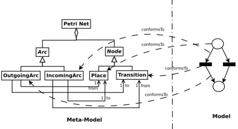
2.7. Petri Net meta-model and a Petri Net model example. . . 26
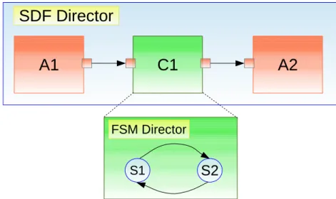
2.8. Composition between Synchronous Data Flow and Finite State Machine in Ptolemy II. . . 28
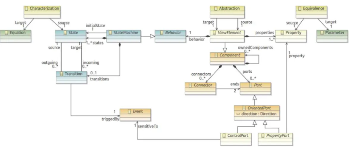
3.1. PRISMSYS Framework meta-model. . . 34
3.2. Relationship between Abstraction correspondence and viewElement. . . 36
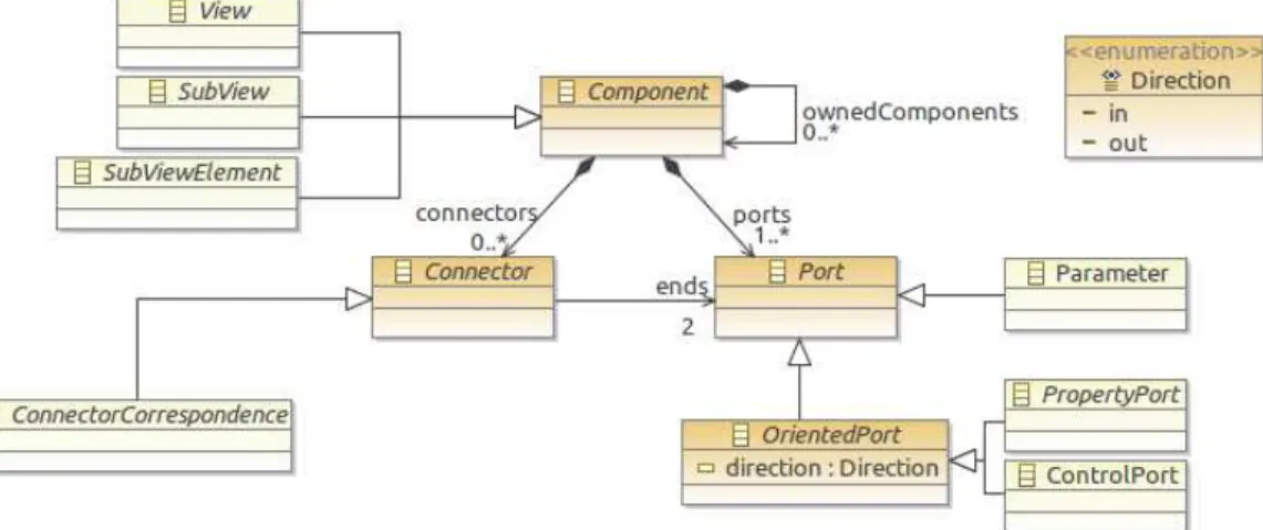
3.3. Component meta-model and its relationship with View, SubView, Sub-ViewElement and ConnectorCorrespondence. . . 37
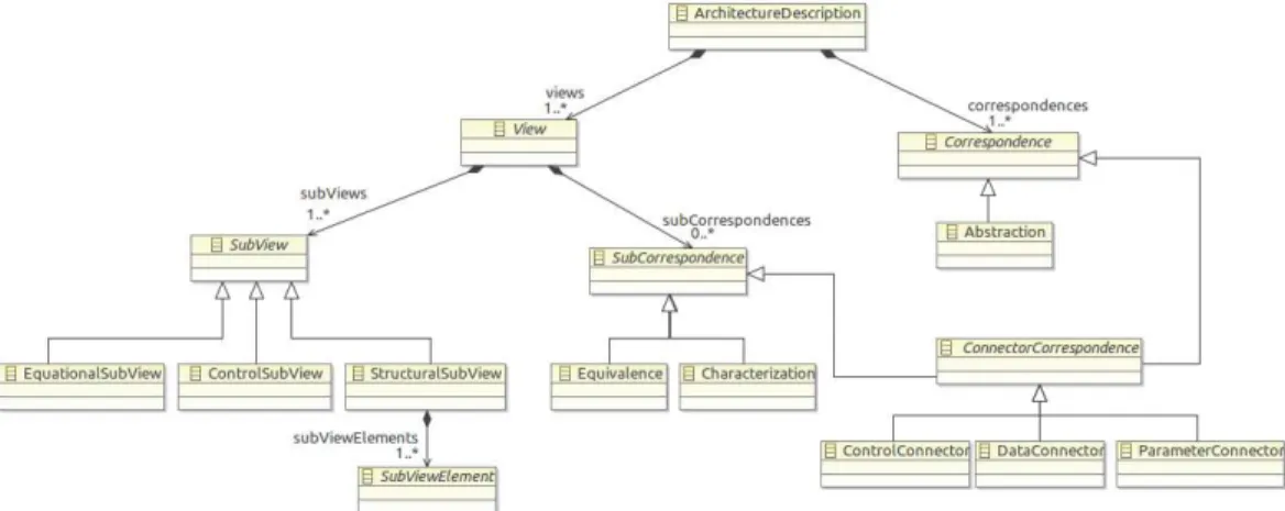
3.4. Correspondences and Sub-Correspondences in PRISMSYS Framework. . 39
3.5. Example of structuralSubViews including the abstraction correspondence. 41 3.6. SubViewElement meta-model. . . 42
3.7. EquationalSubView meta-model. . . 44
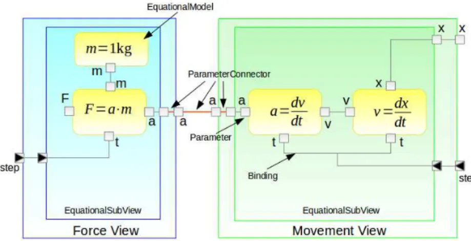
3.8. EquationalSubView Example . . . 45
3.9. Example of the characterization and equivalence correspondences use. . 46
3.10. Controller meta-model . . . 47
3.11. Example of the use of ControlSubView to control the water level of a tank. 48 3.12. Simplified meta-model of EncapsulatedClassifier. . . 52
3.13. State stereotype. . . 53
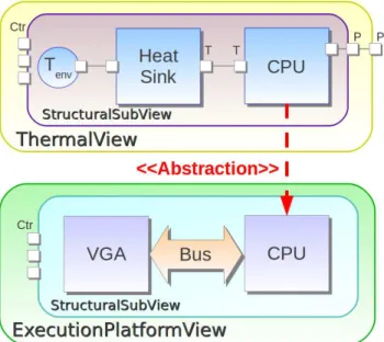
3.14. Abstraction of CPU in a layout component view. . . 54
3.15. Simplified Constraint Block meta-model from the SysML specification. . 56
3.16. Representation of an active state by clocks. . . 60
3.17. Representation of the clock ticks leading to a change between two states caused by a guardEvent. . . 61
3.18. Representation of the clock ticks leading to a change between two states caused by a triggerEvent. . . 63
3.19. PRISMSYS model where the temperature of a CPU is characterized in the equationalSubView. . . 66
3.20. Temperature evolution through time according a predefined execution scenario. . . 69
4.1. CMOS inverter circuit. . . 72
4.2. Leakage currents of a NMOS transistor. . . 74 x
List of Figures xi
4.3. Example of a clock gating implementation. . . 78
4.4. Example of a power gating implementation. . . 79
4.5. Example of a retention register. . . 79
4.6. Example of Power Domain association. . . 83
5.1. Hardware View meta-model.. . . 90
5.2. Hardware View of the PRISMSYS power-aware model.. . . 91
5.3. Application View Meta-model. . . 92
5.4. Application View of the PRISMSYS power-aware model. . . 93
5.5. Power View Meta-model. . . 94
5.6. Power View of the PRISMSYS power-aware model without including its equationalSubView. . . 96
5.7. EquationalSubView of PowerView. . . 98
5.8. Clock View Meta-model. . . 100
5.9. Clock View of the PRISMSYS power-aware model without including its equationalSubView. . . 101
5.10. Equational Sub-view of Clock View. . . 102
5.11. Thermal view Meta-Model. . . 103
5.12. Thermal view of the PRISMSYS power-aware model. . . 104
5.13. Equational Sub-View of Thermal View. . . 105
5.14. Example of the Abstraction and ControlConnector correspondences be-tween PowerView and HardwareView. . . 106
5.15. Example of Allocation correspondence between ApplicationView and Hard-wareView. . . 107
5.16. Example of Characterization sub-correspondence in PowerView.. . . 108
5.17. PRISMSYS Power-Aware Model Overview. . . 110
6.1. Overview of the PRISMSYS framework co-simulation implementation. . 113
6.2. Sequence diagram of the PRISMSYS model Simulation. . . 114
6.3. Execution of ApplicationView and its interaction with HardwareView. . 116
6.4. ApplicationView simulation in TimeSquare. . . 120
6.5. Execution of the HardwareView controlSubView and its interaction with ApplicationView, PowerView and ClockView. . . 122
6.6. HardwareView simulation in TimeSquare. . . 124
6.7. Execution of the ClockView controlSubView and its interaction with its internal subViewElements and with HardwareView. . . 126
6.8. ClockView simulation in TimeSquare. . . 128
6.9. Execution of the HardwareView controlSubView and its interaction with ApplicationView, PowerView and ClockView. . . 130
6.10. Power View simulation in TimeSquare.. . . 132
6.11. Thermal View simulation in TimeSquare. . . 134
6.12. Transformation Overview. . . 137
6.13. Simplified Aceplorer meta-model. . . 138
6.14. Control View Scenario generated by TimeSquare (above) and the power consumption response in Aceplorer (below). . . 143
List of Tables
3.1. PRISMSYS - UML Mapping. . . 51
3.2. PRISMSYS - MARTE Mapping. . . 54
3.3. PRISMSYS - SysML Mapping. . . 56
3.4. Clocks representing the relevant actions in a Finite State Machine for both SubViewElement and Controller. . . 59
6.1. Action execution in cpu clock cycles and time. . . 126
6.2. Multi-View - Aceplorer Mapping. . . 139
Abbreviations
ATL ATLAS Transformation Language CPF Common Power Format
CTM Compact Thermal Model
DVFS Dynamic Voltage-Frequency Scale DSML Domain Specific-Modeling Languages ESL Electronic System-Level
FSM Finite State Machine
HDL Hardware Description-Language
MARTE Modeling and Analisis of Real Time and Embedded Systems MDA Model-Driven Architecture
MDE Model-Driven Engineering MOF Meta Object Facility MoC Model of Computation NFP Non-Functional Property EMF Eclipse Modeling Framework QVT Query View Transformation RTL Register-Transfer Level SysML Systems Modeling Language TLM Transaction-Level Modeling UML Unified Modeling Language UPF Unified Power Format VCD Value Change Dump
VHDL VHSIC Hardware Description Language VSL Value Specification Language
Chapitre 1
Introduction (Version en
Français)
La notion de système englobe des environnements plus ou moins complexes. Les té-léphones filaires autrefois limités à l’aspect communication ont été remplacés par les téléphones GSM qui combinent l’envoi de texto, le guidage GPS des utilisateurs, la lec-ture d’un journal et/ou d’un livre ou encore la navigation sur Internet. Les systèmes ont aussi été mis-à-jour avec une technologie plus sophistiquée, où l’optimisation de certaines propriétés est une priorité aujourd’hui. Les systèmes électroniques sont maintenant in-tégrés dans les voitures, les avions, les bateaux et les trains. Ces systèmes numériques se veulent plus efficaces et plus flexibles que les systèmes purement mécaniques en aidant à réduire la consommation de carburant, les coûts de maintenance et en améliorant la qualité fonctionnelle.
Dans le but de gérer la complexité des systèmes modernes, les architectes des systèmes divisent les aspects en plusieurs domaines. Chaque domaine est conçu, étudié et ana-lysé par des experts spécifiques qui s’y intéressent spécifiquement. Ces préoccupations sont quantifiées par les propriétés établies dans le cahier des charges du système. Ces propriétés peuvent être soit fonctionnelles (arrêter une voiture quand la pédale du frein est appuyée), ou non fonctionnelles (déterminer un budget sur la consommation de puissance et de carburant, les temps de réponse, la taille et les coûts). Habituellement, les experts ont leurs propres langages et outils pour modéliser et analyser un domaine
Chapitre 1. Introduction (Version en Français) 2 spécifique. Cependant, ces domaines sont liés et interagissent afin de respecter les exi-gences du système. Par exemple, dans les voitures électriques ou hybrides, l’action de freinage pourrait générer de l’énergie qui peut être stockée dans les batteries pour être réutilisée lorsque la voiture a besoin d’accélérer. Ce cycle peut réduire la consomma-tion de puissance ou de carburant de la voiture en améliorant certaines propriétés non fonctionnelles.
Nous proposons d’exprimer comme des vues, chacun des domaines du système. IEEE-1471 [1] et IEEE-42010 [2] sont des standards qui proposent une structure générique afin de spécifier un système avec de multiples vues. Cette manière de décrire un système est appelée modélisation multi-vue. Cependant, ces standards sont extrêmement généraux, ils peuvent donc être appliqués de différentes façons. En plus, en utilisant ces standards, c’est difficile de décrire les concepts réutilisables définis dans une architecture pour les appliquer ailleurs.
Dans cette thèse, nous proposons PRISMSYS, un langage de modélisation muti-vue qui permet de spécifier les domaines des experts dans une variété de vues. PRISMSYS est inspiré par les concepts définis dans IEEE-42010 [2]. Néanmoins, nous proposons des éléments spécifiques inclus dans les vues, ses comportements, ses associations et ses interactions. En utilisant l’Ingénierie Dirigée par les Modèles, nous donnons une syntaxe à PRISMSYS, i.e., la structure de l’architecture du système. La structure de PRISMSYS est spécifiée par un méta-modèle.
PRISMSYS inclut deux types de comportements : un comportement à événements dis-crets, représenté par des machines à états et l’interaction parmi des vues définie par des événements. Il prévoit aussi un comportement EN temps continu, exprimé par des 2quations. Nous définissons la sémantique d’exécution de ces comportements en utili-sant ccsl [3], un langage déclaratif qui décrit les relations causales et temporelles entre événements. En employant ccsl, nous spécifions la coordination du comportement des différents domaines d’exécution. Nous orchestrons aussi les différent modèles (a priori hétérogènes) du comportement dans les vues définies, comme la synchronisation entre l’activation des états d’une machine à états finis (un comportement à événements dis-crets) et l’évaluation des équations (un comportement en temps continu).
Nous représentons PRISMSYS comme un profil uml. Le profil de PRISMSYS utilise autant que possible les concepts définis dans les profils uml SysML [4] et marte [5].
Chapitre 1. Introduction (Version en Français) 3 Une fois que la sémantique d’exécution de PRISMSYS est définie, nous utilisons TimeS-quare [6] afin de simuler la partie discrète du modèle. Pour évaluer la partie continue, nous choisissons Scilab [7], une outil de calcul numérique qui offre les fonctions pour ré-soudre les équations. Nous avons développé un connecteur entre TimeSquare et Scilab pour orchestrer la simulation discrète avec la partie continue.
Pour illustrer le potentiel de PRISMSYS, nous avons développé un modèle d’un système dont la principale préoccupation est la consommation de puissance. Dans ce modèle, nous définissons les vues et les éléments qui décrivent et impactent la consommation de puissance d’un système. Ce modèle est simulé et les comportements discrets et continus sont présentés (e.g., le comportement de la machine d’états finis, et aussi l’évolution de la consommation de puissance et la température). Finalement, nous proposons une autre manière d’utiliser le modèle PRISMSYS. Nous spécifions une transformation du modèle PRISMSYS vers un autre modèle d’un outil de domaine spécifique. En prenant comme cas d’étude le modèle PRISMSYS dédié à la consommation de puissance, nous le transformons dans le format interne d’Aceplorer afin de simuler et analyser la consom-mation de puissance. Aceplorer [8] est un outil commercial qui modélise et simule le comportement de la consommation de puissance d’un système. Aceplorer a été utilisée dans le cadre du projet ANR-HeLP (référence ANR-09-SEGI-006).
Le contenu de cette thèse est organisé en deux parties principales : La définition de la structure de PRISMSYS, et le développement du cas d’étude de PRISMSYS, un modèle du système dédié à la consommation de puissance.
La première partie introduit les concepts principaux de la modélisation multi-vue et de l’hétérogénéité du comportement spécifié dans le modèle d’un système. En conséquence, cette partie est consacrée à la spécification de la structure de PRISMSYS. Cette partie est composée des chapitres 2 et 3. Le premier chapitre introduit l’état de l’art des préoccupations structurelles et comportementales afin de modéliser les systèmes. Nous introduisons les concepts de modélisation multi-vue identifiés par la spécification IEEE-42010. Finalement, Nous identifions une relation entre la modélisation multi-vue et la composition des modèles. Sur les préoccupations comportementales, nous introduisons la notion de Modèle de Calcul (MoC), les outils qui les implémentent, comme Ptolemy II [9] et ModHel’X [10], et nous discutons également le problème d’hétérogénéité parmi différents MoCs. Le chapitre 3 définit la structure de PRISMSYS, sa syntaxe et sa
Chapitre 1. Introduction (Version en Français) 4 sémantique pour spécifier un modèle multi-vue d’un système. La syntaxe de PRISMSYS est spécifié par un meta-modèle. PRISMSYS suit une approche par composants, où les concepts multi-vue sont specifiés en accord avec cette approche. Une vue est exprimée par trois sous-vues principales : controlSubView, StructuralSubView et EquationalSubView. Chaque sous-vue joue un rôle spécifique dans la construction d’une vue.
La deuxième partie de cette thèse est dédiée à la modélisation d’un système dont la préoccupation principale est la consommation de puissance. Ce modèle est défini en utilisant la structure de PRISMSYS. Cette partie de la thèse est composée des chapitres
4,5and6. Le chapitre4introduit les concepts, les techniques, et les outils employés pour modéliser la consommation de puissance d’un système. Nous spécifions les vues et ses éléments afin d’évaluer et d’analyser le modèle PRISMSYS dédié à la consommation de puissance dans le chapitre5. Nous simulons, évaluons et analysons le modèle PRISMSYS dédié à la consommation dans le chapitre 6 en utilisant TimeSquare, Scilab et le connecteur Scilab Solver construit pour l’occasion. Dans ce chapitre, nous spécifions également la transformation de PRISMSYS vers Aceplorer.
Finalement, nous concluons ce travail, en soulignant les contributions principales et nous donnons quelques perspectives futures dans le chapitre 7.
Chapter 1
Introduction
Nowadays, the complexity of systems is increasing. It began with simple devices that performed a specific functionality, such as a telephone that makes calls through a cable, and now, these devices are much more complex including new functionalities and new technologies. For instance, the telephone is being replaced by mobile phones, which are wireless and have multiple functionalities such as sending messages, orienting people to arrive to a destination or allowing to read news and books or to surf on the Inter-net. Systems have also been upgraded with a more sophisticated technology, where the optimization of certain properties is a priority today. Electronic systems are now integrated in cars, airplanes, boats and trains. These systems are more precise than the mechanical ones helping to reduce gas consumption, maintenance costs and improving the functional quality.
To deal with the complexity of modern systems, system architects split them in vari-ous domains. Each domain is designed, studied and analyzed by experts that specify determined stakeholder’s concerns. These concerns are quantified by properties stated in system requirements. Such properties can be either functional, such as stopping a car when the brake pedal is pressed, or non-functional, like power and gas consumption, time performance, size and costs. Usually, the experts have their own languages and tools to model and analyze a specific domain. However, these domains are connected and they interact to fulfill the system requirements. For instance, in electric or hybrid cars, the braking action could generate some energy that can be stored in batteries to
Chapter 1. Introduction 6 be re-used once the car needs to accelerate. This cycle can reduce the power or gas consumption of the car, improving certain non-functional properties.
The multiple domains that could be defined in a system are tackled by expressing them in views. IEEE-1471 [1] and IEEE-42010 [2] are standards that propose a generic framework to specify a system in multiple views. This way to describe a system is named multi-view modeling. Nevertheless, these standards are extremely general, therefore they can be applied in different ways. Moreover, by using these standards, it is difficult to describe re-usable concepts defined in an architecture in order to apply them in a different one. In this thesis, we propose PRISMSYS, a multi-view modeling language that allows spec-ifying expert’s domains in various views. PRISMSYS is inspired by the concepts defined in IEEE-42010 [2]. However, we propose specific elements included in the views, their behavior, associations and interactions. By using Model Driven Engineering, we give a syntax to PRISMSYS, i.e., the system architecture structure. The PRISMSYS struc-ture is specified by meta-models. Model Driven Engineering defines a clear separation of abstraction levels where meta-model is one of them. Thanks to these abstraction levels, we can split those specified in IEEE-42010.
PRISMSYS includes two kinds of behaviors: a discrete event behavior, represented by state machines and the event interaction between views, as well as a continuous time behavior, expressed by equations whose values are evaluated through time. We define the execution semantics of this behavior in ccsl [3], a declarative language that describes causal and temporal relationships between events. By employing ccsl, we specify the coordination of the behavior from different execution domains. We also orchestrate the heterogeneity in the behavior modeling in the defined views, such as the synchronization between a finite state machine (a discrete event behavior) and the evaluation of an equation (a continuous time behavior).
We represent PRISMSYS in uml by specifying a profile. The PRISMSYS profile uses as much as possible the concepts defined in other uml profiles, such as SysML [4] and marte [5]. The concepts that are not included in uml or in the other two profiles, are defined as stereotypes in the PRISMSYS profile, extending the uml concepts whose meaning is compatible with the PRISMSYS concept semantics.
Chapter 1. Introduction 7 Once the semantics of the PRISMSYS execution is defined, we use TimeSquare [6] to simulate the discrete part of the model. To evaluate the continuous part, we chose Scilab [7], a numerical computing tool that provides the functions to solve equations. We have developed a connector between TimeSquare and Scilab to orchestrate the discrete simulation with the continuous one.
To prove the potential of PRISMSYS, we have developed a model of a power-aware system. First, we introduce a background in power consumption characterization and power management. We continue defining the views and the elements that describe and impact the power consumption of a system. This model is simulated and the discrete and continuous behaviors are depicted (e.g., finite state machine behavior, and also power and temperature evolution). Finally, we propose another way to use the PRISMSYS model. We specify a transformation of the PRISMSYS model to a model of a specific domain tool. Taking as use case the PRISMSYS power-aware system model, we transform it to an Aceplorer model in order to simulate and analyze the power consumption. Aceplorer [8] is a commercial tool that models and simulates the power behavior of a system. Aceplorer was used in the context of the ANR Project HeLP (reference ANR-09-SEGI-006).
The content of this thesis is organized in two main parts: The definition of the PRISM-SYS framework, and the development of the PRISMPRISM-SYS use case, a power-aware system model.
The first part introduces the main concepts of multi-view modeling and highlights the behavior heterogeneity specified in a system model. Therefore, this first part is the stronghold in the specification of the PRISMSYS framework. This part is composed of chapters2and3. The former introduces the background about structural and behavioral concerns to model systems. We present that the complexity of a system architecture could be managed following the multi-view approach. We introduce the multi-view concepts specified in 42010. We also split the abstraction level defined in IEEE-42010 by using the Model-Driven Engineering abstraction levels. Finally, we identify a relationship between the multi-view modeling and the model composition. In the be-havioral concerns, we introduce the notion of Model of Computation (MoC), the tools that implement them, such as Ptolemy II [9] and ModHel’X [10], and we also discuss the
Chapter 1. Introduction 8 heterogeneity problem between various MoCs. Chapter3defines the PRISMSYS frame-work, its syntax and semantics to define a multi-view system model. The PRISMSYS syntax is specified by meta-models. PRISMSYS follows a component approach, where the multi-view concepts are specified accordingly. A view is expressed by three main sub-views: controlSubView, StructuralSubView and EquationalSubView. Each sub-view plays a specific role in the construction of a view.
The second part of this thesis is dedicated to the modeling of a power-aware system by using PRISMSYS. This part consists of chapters 4, 5and 6. Chapter 4introduces the concepts, techniques, and tools employed to model the power consumption of a system. We specify the views and their elements to describe various domains that are involved in the system power consumption in Chapter 5. We simulate, evaluate and analyze the PRISMSYS power-aware model in Chapter 6 by using TimeSquare, Scilab and their connector Scilab Solver. In this chapter, we also specify the transformation of PRISMSYS to Aceplorer.
Finally, we provide the conclusion of this work, highlighting its main contributions and we give some future perspectives in Chapter 7.
Chapter 2
Background
Contents 2.1. Introduction . . . 10 2.2. Structural Concerns . . . 10 2.2.1. Multi-View Modeling . . . 112.2.2. Multi-View Approaches and Model Composition . . . 15
2.2.3. Discussion. . . 23 2.3. Behavioral Concerns . . . 24 2.3.1. Models of Computation . . . 25 2.3.2. Heterogeneous Models . . . 27 2.3.3. Discussion. . . 29 2.4. Conclusion . . . 30 9
Chapter 2. Background 10
2.1. Introduction
Systems have a strong foothold in our daily life. In the customer electronics market, mobile phones, tablets, video and music players, and TVs are some examples of these systems. They provide a quick and direct access to the information (email, news, arti-cles, books, etc) and they are marking a milestone in communications, giving a great mobility to consumers. These systems are also installed in cars, airplanes, boats and submarines to upgrade certain mechanical controllers or optimize energy consumption, time performance and costs. Medicine is also an important domain where systems play an important role, e.g., measuring blood pressure, dosing medicament or pacing the heart.
Experts from different domains work together in the design of systems. These experts fulfill the strict system requirements, generally specified by non-functional properties such as time performance, security, power consumption, temperature and cost. Each expert has his/her own language to describe the model of the system from his/her point of view. Therefore, a system model is represented by multiple languages where each language satisfies certain system requirements.
Whatever its complexity, a language is always defined by a syntax and a semantics. In this thesis, we use the term “syntax” to refer to the structural definition of the language. In contrast, the term “semantics” describes the behavior of the language.
In this chapter, we present the concepts and the approach that we use in this thesis to define the structure and the behavior of the languages that model systems.
2.2. Structural Concerns
According to IEEE-1471 [1], a system is “a collection of components organized to ac-complish a specific function or set of functions”. This standard also defines architecture as “the fundamental organization of a system embodied in its components, their rela-tionships to each other, and to the environment, and the principles guiding its design and evolution”. Taking into account these two definitions, an architecture specifies the structure of a system, based on a component approach.
Chapter 2. Background 11 To define a system architecture, it is important to identify the elements involved in the design of a system. IEEE-15288 standard [11] defines a system as “man-made, created and utilized to provide products and/or services in defined environments for the benefit of users and other stakeholders”. Following this definition, we identify that a system is associated with two main entities: environment and stakeholder. Figure 2.1presents a conceptual model of the identified elements that are associated with a system. In this figure, a system responds to the stakeholder needs and it is placed in an environment. An environment may contain other systems or subsystems that interact with each other. A system exposes one and only one architecture.
Figure 2.1: Conceptual model for the system architecture context from [2].
The stakeholder needs are represented by concerns in IEEE-1471 [1]. These concerns are defined in various specific domains that are studied by different experts. These experts build system models that include functional and non-functional properties to tackle the concerns related to their domain. The modeling activity where concerns are divided into various domains is called multi-view modeling.
In Section2.2.1, we present the main concepts of multi-view modeling using the IEEE-42010 standard [2]. This standard is a reference in this kind of modeling.
2.2.1. Multi-View Modeling
Multi-view modeling was proposed as a solution to manage the complexity of the system design. This technique defines a system architecture in different views where each view addresses a set of stakeholder’s concerns [1]. Views are defined by domain experts that have their own concepts and languages to express the domain elements and their relationships. An example of this modeling technique is applied to construction. To construct a building, architects design floor plans, electrical engineers draw electrical blueprints and hydraulic engineers create pipe networks. The electrical blueprints and
Chapter 2. Background 12 the pipe networks are defined based on the floor plans, therefore, in this particular case, there is a reference model to build the other domain models. Similar to the construction domain, systems can be specified with diverse views; for instance, power consumption view, financial view, structural view and time performance view.
In this thesis, we use the vocabulary specified in the IEEE-42010 standard [2] to describe the multi-view concepts. This standard is an updated version of IEEE-1471 [1] and it is inspired by various multi-view approaches such as DoDAF [12], MODAF [13], TOGAF [14], the “4+1” view model [15] and Zachman’s framework [16].
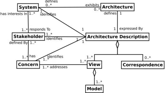
According to the IEEE-42010 standard, a system architecture is represented by an archi-tecture description. The standard emphasizes that an archiarchi-tecture is “abstract, consisting of concepts and properties”, whereas architecture description is a work-product used to define an architecture. Figure2.2presents the conceptual model defined in IEEE-42010. In the figure, an architecture description owns views and correspondences. A view con-tains models that are the modeling artifacts describing the view. Correspondence builds associations among architecture elements that define the considered system, i.e., the relationship between models, views, the architecture description, stakeholders, and con-cerns. The main purpose of Correspondence is to identify the view elements that have some kind of association in a system architecture in order to maintain the consistency of the architecture description.
Chapter 2. Background 13 This standard also specifies a mechanism to build architecture descriptions which could be reused in various projects that share the same architecture concepts. For this ob-jective, IEEE-42010 introduces the Architecture Framework concept. Architecture de-scription is the reification of architecture framework, i.e., the architecture framework concepts are used to build the architecture description of a system architecture. Fig-ure2.3presents the conceptual model of architecture framework. An architecture frame-work owns viewpoints, and correspondence rules. Views and correspondences conform to viewpoints and correspondence rules, respectively. A viewpoint contains model kinds where models conform to them.
Figure 2.3: Architecture Framework concept model [2]
IEEE-42010 defines a conceptual model where architecture framework concepts and ar-chitecture description concepts are mixed, i.e., models, model kinds, views, viewpoints, correspondences and correspondence rules are contained in an architecture description. Demirli et al. [17] consider that architecture framework concepts and architecture de-scription concepts are different abstraction levels. Demirli proposes to use the Model-Driven Engineering approach to model the abstraction levels of the architecture defined in IEEE-42010.
Model-Driven Engineering (MDE) is a software design technique where the main ar-tifact is model. The Object Management Group (OMG) defines that “a model is a representation of a part of the function, structure and/or behavior of a system. The model specification is based on a language that has a well-defined form (syntax), mean-ing (semantics) and possible rules of analysis, inferences or proof for its constructs.” [18]. According to this definition, a model is built based on a language that gives the necessary expressivity to represent the elements of a specific domain. This language is described through a meta-model. A meta-model expresses the concepts and relationships to build
Chapter 2. Background 14 a model. A meta-model is a model by itself, so that it has another language that con-tains the required concepts and relationships to define one or more meta-models. Such a language is called meta-meta-model. Examples of meta-meta-models are MOF [19] and Ecore [20]. MDE does not propose another language to build meta-meta-models. A meta-meta-model is rather considered as a self-defined model, i.e., its concepts and relationships are represented by them-selves. This self-definition avoids the multiplica-tion of abstracmultiplica-tion levels. In Figure 2.4, we present the abstraction levels in MDE. In the figure, we identify an association of conformity between the concepts of each level, i.e., each level relies on the concepts defined in the upper abstraction level. The M0 level denotes the real world. In this level, the concrete objects are represented by the elements of a model.
Meta-Meta-Model
Meta-Model
Model
Object
conforms to conforms to conforms To represented byM0
M1
M2
M3
Figure 2.4: Abstraction levels in MDE.
Following the MDE abstraction levels, Demirli identifies that the architecture framework conceptual model is the meta-model of architecture description conceptual model. Fig-ure 2.5 depicts the abstraction level representation of IEEE-42010 concepts according to Demirli’s work [17].
Chapter 2. Background 15
Architecture
Framework ViewPoint ModelKind CorrespondenceRule
1..* 1..* 1..*
Architecture
Description View Model Correspondence
1..* 1..* 1..* Conforms to Conforms to Conforms to Conforms to
M1
M2
Figure 2.5: Abstraction levels of IEEE-42010 concepts [17].
MDE offers two alternative solutions for the definition of models: either through a General-Purpose Modeling Language (GPML) or through a Domain-Specific Modeling Language (DSML). GPML proposes to use a unique meta-model that has enough ex-pressivity to define any domain. uml [21] and XML are examples of GPMLs. DSML proposes to define one dedicated meta-model for each specific domain. SysML [4], marte [5], AADL [22] and ATL [23] are examples of DSMLs. Hence, we consider ar-chitecture framework as a set of DSMLs with a set of correspondence rules between the DSML elements.
An example of the IEEE-42010 implementation is MEGAF [24]. MEGAF is a tool to build architecture frameworks according to the IEEE-42010 standard. This infrastruc-ture allows creating viewpoints, stakeholders and concerns to describe a specific system. MEGAF also defines associations between the specified architecture elements to enable consistency checks based on the defined correspondences.
In the following subsection, we present approaches based on the multi-view modeling requirements defined in IEEE-42010. We also explore an alternative solution through the so-called /model composition/ and we compare the two solutions.
2.2.2. Multi-View Approaches and Model Composition
There are two approaches that use the multi-view concept specified in IEEE-42010: synthetic and projective [2]. A synthetic approach defines one viewPoint for each specific domain, independently. It integrates these viewPoints in an architecture framework by
Chapter 2. Background 16 using correspondence rules. In contrast, a projective approach specifies a reference meta-model, where the viewPoints are built by hiding irrelevant elements from its meta-model. In this approach, correspondence rules are already defined in the reference meta-model. Model composition is another modeling approach used in software engineering to com-bine models with a specific purpose. These models can conform to a common meta-model, or to different ones. Clavreul [25] defines that Model Composition is an activity that “enables to build a system from the union of independent or dependent software artifacts”.
Similarly to the multi-view approaches, model composition specifies correspondences be-tween the elements of the models (or meta-models) to be combined. Clavreul defines four main types of correspondences to classify the model element relationships. These corre-spondences are: operator-based, rule-based, model-based and delta representation-based. Operator-based is a set of functions whose actions define the correspondences among model elements. Rule-based finds the similarity between model elements, such as term-matching on names or satisfies certain constraints to associate model elements, such as pre- or post-conditions. Model-based is a correspondence type that is formally defined as part of the modeling language specification, e.g., DSMLs. Finally, delta representation-based is a correspondence that identifies by analysis the differences between two or more versions of the same model.
Clavreul also identifies various interpretations to these correspondences. He defines two interpretation categories in modeling structural associations: overlapping and cross-cutting. Overlapping is to merge one or more models gathering the model elements that have equal or similar interpretation. Cross-cutting is to weave new model elements (aspects) to a base model, modifying the structure and/or behavior. Clavreul also defines two additional categories: add and delete. These categories insert/delete model elements in a model. Clavreul considers that the designer must know the internal model structure in order to use the latter two categories. In contrast, using the previous three interpretation categories does not require a knowledge of the internal model structure to define correspondences.
Multi-view approaches and model composition have in common the notion of correspon-dence. Clavreul defines correspondence as “any kind of implicit or explicit relationships
Chapter 2. Background 17 between sets of models or sets of model elements”. This definition is shared with IEEE-42010. However, IEEE-42010 specifies correspondence through correspondence rules, i.e., a correspondence is the use of a correspondence rule definition in a model.
The correspondence and interpretation given by Clavreul could be applied to the def-inition of correspondence rules. Nevertheless, the application of correspondence rules in model composition and the multi-view approaches are different. While the synthetic approach only uses correspondence rules to associate concepts of various DSMLs with-out generating a new DSML, model (or meta-model) composition has as goal to get a resulting model (or meta-model) that is built by combining one or more models of the same language or from different languages using correspondence rules. In the case of the projective approach, correspondence rules are defined in the reference meta-model from where the viewPoints are derived.
Figure 2.6depicts the relationship between languages, defined by meta-models, and the modeling approaches. In this figure, MM1 and MM2 are independent meta-models (or languages). The elements of both meta-models are associated by correspondence rules. The correspondence rules can be in both senses, i.e., they associate elements from MM1 to MM2 or vice versa. The two languages (MM1 and MM2 ) and their correspondence rules define a multi-view synthetic approach. The idea of this approach is to define the correspondence rules between viewPoint elements, in order to maintain the coherence between viewPoints. Using the synthetic approach, we can generate a composed language (MM3 ) that is the result of the interpretation of correspondence rules between MM1 and MM2. The projective approach is the decomposition of a language in other languages, i.e., MM3 can be decomposed in MM1 and MM2. The correspondence rules in MM3 are internal relationships between its elements, i.e., it is part of the domain definition. Therefore, the composition of MM1 and MM2 keeps the correspondence rules defined between MM1 and MM2. Once the projective approach is applied, the correspondence rules between MM1 and MM2 are identified in MM3 in order to extract such correspondences and to define associations between MM1 and MM2.
Chapter 2. Background 18
Figure 2.6: Relationship between modeling approaches and specific domains.
It is important to note that the multi-view approaches have as objective to maintain the independence between specific domains. Correspondence rules are the connections that these domains have. In contrast, the aim of the composition modeling approach is to generate a model (or meta-model) that contains the elements of the source models according to the correspondence rules. We could apply the composition approach in a multi-view model to generate analysis models from a selected number of views (projective or synthetic) to a specific purpose. These analysis models could study the impact of the modeled concerns from different views of a system. For instance, the impact of increasing the clock frequency in power consumption and time performance.
In the following items, we analyze some examples that are somehow associated with synthetic, projective and composition approaches:
Aspect-Oriented Programming: In an object-oriented program, the non-functional and the cross-cutting concerns are interwoven in the code. Kiczales et al. [26] pro-pose to extract these non-functional and cross-cutting concerns from the main concern of the program. These extracted concerns are known as aspects. The composition of aspects in the main code is called weaving. An aspect is composed by an advice and a pointcut. The former is the code of the concern that is woven in a specific place of the main code (joint point). The latter identifies the joint point where the aspect is added in the main code. An example of language that implements this kind of programming is AspectJ [27].
This programming approach follows the model composition approach. The aim is to weave aspects into a base model to build a composed model. A set of aspects is
Chapter 2. Background 19 not a view of the model and does not specify specific domains such as the multi-view approach. All the models (aspects and base model) are specified using the same language, i.e., the elements of a model (aspects), conform to a meta-model, are injected (woven) to another model that conforms to the same meta-model. The joint points are correspondences between the aspects and the target model. Kompose: Kompose [28] is a generic model composition tool that merges models conforming to the same meta-model. The merging process is defined by two main steps: matching and merging. Matching identifies the elements that have the same concepts in the models that are to be composed. Merging generates a model that is the result of merging the matched elements. The elements that are not matched, are defined in the resulting model without any changes.
Kompose follows the model composition approach. Matching process identifies the correspondences between the elements of the models to be composed. According to Clavreul, the Kompose correspondences are rule-based and their interpretation is overlapping, i.e., the elements that fulfill the defined composition rules are merged adding the non-common attributes and relations of each element. These composition rules are defined by a pattern between the elements of the models to compose. This pattern is generally found in the equivalence of the semantics and the structure of the elements to merge.
VUML:View-based UML (VUML) [29] is a uml profile that uses the multi-view modeling to provide limited access to the system actors1 through views. The
VUML author points out that the given IEEE-1471 [1] recommendations to build system architectures are specified in a general way, and it does not propose the use of a language to be implemented. VUML is a language inspired by the IEEE-1471 concepts to model system architectures. VUML employs a base class diagram of the system to extract the actors’ views according to the actor’s access rights. The view defines the system elements (classes, attributes and methods) that the user can access in the system.
VUML defines a common stereotype called DefaultView. This class owns the ele-ments that are shared between the system actors. Other views are specified accord-ing to the actor’s access rights. Theses classes are stereotyped by View and they
1
Chapter 2. Background 20 contain the elements only related to the actor’s profile. Views and DefaultView are associated by uml dependency associations stereotyped by view-extension. This association allows accessing to the information shared among actors. VUML also defines relationships among Views to guarantee the correct updating of informa-tion among the views that share system elements. This relainforma-tionship is represented by a dependency association stereotyped by view-dependency. The attributes de-pendency between views is constrained by OCL2 expressions.
VUML follows the projective approach. From a base meta-model, the viewPoints are extracted according to the user’s profile. We identify that view-extension and view-dependency are correspondence rules between viewPoints. According to the Clavreul’s correspondence types, both VUML correspondence rules are model-based, they are defined in the language specification. We also identify that the correspondence interpretation is overlapping: each view contains part of the fea-tures of the reference model and these feafea-tures can be shared among views, i.e., a feature of the reference model can be included in one or more views.
SysML:System Modeling Language (SysML) [4] is an OMG3specification that
specifies a uml profile for systems engineering domain. Some of the elements of this standard represents the main IEEE-1471 standard concepts to define a multi-view approach. SysML uses packages to represent views, classes to describe viewpoints, and conform associations to specify relationships between views and viewpoints. This conform relationship is represented by a uml dependency association. The SysML viewpoint contains two properties: stakeholders and concerns. These properties are defined by strings. Therefore, the stakeholders and concerns shared among viewpoints must be rewritten in each viewpoint without guaranteeing the conformance among viewpoints.
The SysML View limits the package elements to comments, constraint elements, package import and element import; therefore, the view elements must be defined in a common model to be imported and constrained according to the view. SysML also specifies that a view must follow the methods and languages defined in the as-sociated viewpoints. However, SysML does not define a verification policy for the
2
The Object Constraint Language (OCL) is a language defined by the OMG to constrain UML models.
3
Chapter 2. Background 21 concerned viewpoint properties. Moreover, methods and languages are represented as strings in Viewpoint, making the verification task more difficult.
SysMLimplements a projective approach where each view is built by the element models imported from the main model. However, there are not explicit correspon-dences between views. Moreover, a viewpoint does not have the same meaning as in IEEE-42010 or IEEE-1471, but rather it is interpreted as the viewpoint features that a view must answer. SysML viewpoint does not define the language used to express views. The conform association is not a correspondence according to the way we interpret the IEEE-42010. This association represents that the view elements conform to the concerns defined by stakeholders from their point of view and it is not a relationship between model elements from different views.
Obeo Designer: Obeo Designer is a system design tool developed by Obeo4. This tool not only allows system modeling through graphical modeling standard languages such as uml and SysML, but it also provides a graphical environment to build DSMLs in Ecore. Obeo Designer includes viewpoints that are a specific representation of the concepts from one or more meta-models. These representa-tions can be predefined (tables, trees, diagrams) or they can be customized by the system designer5.
We consider that Obeo’s Viewpoint concept does not follow any of the multi-view approaches. An Obeo’s multi-viewpoint is a representation of a model, but it does not define a portion of the model (projective approach) or an independent model (synthetic approach).
Hybrid multi-view modeling: Cicchetti et al. [30] present a multi-view model-ing approach that is both projective and synthetic. They define a base meta-model to represent every possible concept of a specific system following the projective approach. However, the architect can build viewPoints in various meta-models following the synthetic approach. The connection between both approaches is in the base meta-model used to create the viewPoints. ViewPoints are defined ac-cording to the base meta-model, therefore the concepts and associations specified in the viewPoint must also be specified in the base meta-model.
4
http://www.obeo.fr/pages/obeo-designer
5
Chapter 2. Background 22 A base model and view models are built and they conform to their corresponding meta-models (base meta-model and viewPoints). The base model is the synchro-nization reference to the other view models, i.e., if a view model is changed, the modifications are propagated initially to the base model and then to the other view models. This synchronization mechanism is implemented according to the difference between the base meta-model and the viewPoints.
This hybrid multi-view modeling approach solves the consistency problem present in the synthetic approach by having a common reference between the defined views. However, we consider that the duplication of information between the view models and the base model is a drawback since it requires some effort to maintain consistency.
In this modeling approach, the correspondences are explicitly defined in the base meta-model. According to Clavreul’s classification, the correspondences specified in Cicchetti’s approach are model-based, i.e., every relationship between view-Points is defined in the base meta-model. Nevertheless, we find that there is also a delta representation-based correspondence in the synchronization between views and the base model when there is a change of information in a view model. Heterogeneous points of view with ModHel’X:Boulanger et al. [31] present a synthetic approach, defining independent views of a system model in ModHel’X blocks. Each block represents an observable behavior of a system. In the context of multi-view modeling, a block specifies the behavior of a system from a specific point of view. For instance, a system could have a functional behavior, a power consumption behavior or a temperature behavior. In this work, the correspon-dences are represented by the behavioral relationships among views, i.e., using the ModHel’X relations, we define the view connections and the way that the view behaviors are synchronized.
This approach proposes to use a single language (defined in ModHel’X) to express the multi-view representation of a system (viewPoints and correspondence rules). However, there is neither a notion of view nor correspondence in this language. Views and correspondences are interpretations of a ModHel’X concept using blocks (views) and relations (correspondences).
Chapter 2. Background 23 The type of correspondences are model-based, they are defined in the ModHel’X meta-model. We consider that their interpretation is associated with the behavior of the model. In Section2.3.1, we present it in details.
2.2.3. Discussion
All multi-view approaches have advantages and disadvantages. The projective approach allows observing a system model from different perspectives or viewPoints focused on the elements and properties that are important for the stakeholders. However, maintaining and extending a unique meta-model to describe every possible view in a system is a difficult task. For instance, in VUML, when a new viewPoint is added to the system meta-model, it can affect the previously defined viewPoints and also their associated information. One possible solution is to define consistency mechanisms to preserve the system model information once a new viewPoint is added. This kind of mechanism is developed in the Cichetti’s work.
The synthetic approach has the advantage of defining independent viewPoints of a sys-tem splitting the syssys-tem concerns. This viewPoint independence allows the definition of new viewPoints without altering the previous ones. However, the main challenge is the definition of correspondence rules between viewPoints. Unlike the projective approach, where the correspondence rules are explicitly defined in the reference meta-model, in the synthetic approach such correspondence rules are not explicit and they must be established once a viewPoint is specified. The domain experts define the relationships between the concepts of the viewPoint concepts.
Model composition could be seen as a way to unify projective and synthetic approaches. For instance, when having a multi-view model that follows a synthetic approach, the correspondences among views could be used to generate composed models that have as main goal the analysis of certain properties of the modeled system and the quantification of the impact of the properties from different points of view. In contrast, a composed model (or meta-model) could represent a reference model (or meta-model) in the multi-view projective approach. Using decomposition rules, multi-viewpoints could be extracted or projected from the reference meta-model and correspondence rules could be identified in the reference meta-model to be explicitly defined in the decomposition process.
Chapter 2. Background 24 The correspondences and interpretations defined by Clavreul cannot be applied only to model composition. We identify that the Clavreul’s correspondences meaning could also be applied to the correspondence rule definition in the multi-view approach. We note that correspondence rules among structural elements of different viewPoints are used to maintain the consistency between viewPoints, i.e., these structural elements could represent a single element, but from a different point of view. We call these kinds of cor-respondence rules syntactic corcor-respondences. In the multi-view modeling examples, we have identified some syntactic correspondences, such as VUML, SysML, Obeo Designer and Ciccheti’s work. However, another kind of correspondences could be applied, i.e., behavioral correspondence rules among viewPoints. This sort of correspondence rules was identified in Boulanger’s work and is further discussed in Section 2.3.1.
Most of the works that apply the multi-view approaches are oriented to the design of software systems. Nevertheless, we consider that such approaches can be also applied to the system design. In this thesis, we propose a multi-view model for system de-sign. The definition of this multi-view model gathers the advantages of both multi-view approaches: the definition of explicit correspondence rules to maintain the model con-sistency and the definition of independent viewPoints for each expert domain. We also use the Clavreul’s terms to identify the correspondence rules among viewPoints. Another important feature to analyze in this chapter is the behavior in a multi-view modeling approach. Identifying the behavioral relationships between viewPoints and placing them in a modeling behavior context. Section2.3presents the description of the behavioral concerns in the design of systems.
2.3. Behavioral Concerns
In multi-view modeling, each viewPoint is described by a language with a specific se-mantics of execution. In a DSML, while the syntactic domain is represented by a meta-model, the semantic domain is defined though different approaches. In the language theory, we can find three types of semantic definitions. The first type is Operational Semantics [32]. It uses functions (endogenous transformations) to manipulate data that represent the execution state of the model. Each execution of these functions repre-sents a step in the model evolution. The second type is Axiomatic semantics [33]. It
Chapter 2. Background 25 characterizes the execution state by properties that enable reasoning about the models and their correct evolution. The last type is Transformational semantics [34]. It is an exogenous transformation from the syntactic domain to an existing language with well defined semantics.
The concurrent theory has also proposed other ways to describe the behavior of a model. This behavior is characterized by the so-called Models of Computation (MoCs).
2.3.1. Models of Computation
A model of computation (MoC) is “a formal abstraction of execution in a computer” [35]. In other words, it defines the behavioral semantics of a model. MoCs are used in different specific domains to express and to evaluate the behavior of a system. For instance, the control experts uses ordinary differential equation (ODE) solvers to analyze the behavior of the system to be controlled in continuous time. However, these solvers discretize the continuous time in order to be computed. The specification that defines the execution rules of these continuous systems in the computing world is a type of MoC. Modelica [36] and Simulink [37] are tools that implement MoCs that allow to model continuous systems and they are often used by control and mechanic experts to represent and to analyze their specific domains.
Ptolemy II [9] and ModHel’X [10] are tools that implement a variety of MoCs. Using these tools, sequential processes, discrete event and continuous time systems can be modeled. These tools share the way they define their modeling syntax, based on the component approach. While Ptolemy II uses actors, ModHel’X uses blocks to describe the structure of the system behavior. However, this generic use of the component-based modeling restricts the application of the DSML approach. Moreover, if we consider that a viewPoint is a DSML in a multi-view approach, the behavioral semantics of the viewPoint could be hardly specified using these tools because of the incompatibility of the structure definition.
On the other hand, we note that MoCs in these tools are independent from the structure definition. Ptolemy II represents the MoCs implementation by directors and ModHel’X calls them with the same name, MoCs. They associate a specific MoC to a determined structure and this MoC manages the execution of the structure elements. The separation
![Figure 2.5: Abstraction levels of IEEE-42010 concepts [17].](https://thumb-eu.123doks.com/thumbv2/123doknet/13090581.385359/30.918.190.785.110.325/figure-abstraction-levels-of-ieee-concepts.webp)