HAL Id: hal-03149656
https://hal.archives-ouvertes.fr/hal-03149656
Submitted on 23 Feb 2021
HAL is a multi-disciplinary open access
archive for the deposit and dissemination of
sci-entific research documents, whether they are
pub-lished or not. The documents may come from
teaching and research institutions in France or
abroad, or from public or private research centers.
L’archive ouverte pluridisciplinaire HAL, est
destinée au dépôt et à la diffusion de documents
scientifiques de niveau recherche, publiés ou non,
émanant des établissements d’enseignement et de
recherche français ou étrangers, des laboratoires
publics ou privés.
Fourcade-Dutin, Hervé Maillotte, Yves Quiquempois, Géraud Bouwmans,
Emmanuel Hugonnot
To cite this version:
Damien Bigourd, Philippe Morin, Jérôme Dubertrand, Coralie Fourcade-Dutin, Hervé Maillotte, et al..
Parametric gain shaping from a structured pump pulse. IEEE Photonics Technology Letters, Institute
of Electrical and Electronics Engineers, 2019, 31 (3), pp.214-217. �10.1109/LPT.2018.2888731�.
�hal-03149656�
Abstract—We investigate optical parametric amplification in a
fiber pumped by a shaped pulse. The temporal structure of the pump impacts directly the instantaneous spectral gain and its temporal measurement is achieved in the spectral domain thanks to a chirped signal with a broad spectrum.
Index Terms—Four wave mixing, Parametric amplifier, fiber
optics
I. INTRODUCTION
Fiber optical parametric amplifier (FOPA) has been widely investigated in the context of telecommunication [1] for its interesting features such as the instantaneous amplification with large bandwidths [2, 3], high gain values [4] and low noise figures [5]. In most cases, the amplification is achieved with continuous waves (CWs) involving a pump with a constant peak power, an amplified signal and a generated idler. In order to reach higher peak power, FOPA is preferably pumped in ps or ns pulsed regime and we often assume that the pump power is constant during the pulse duration [6-8]. However, the temporal shape of the pump pulse plays a crucial role in the amplification process and it can be of great use to target a specific signal profile [9]. Indeed, the instantaneous parametric gain and its spectral shape depends strongly on the power. Therefore, it also has a temporal distribution since a specific gain shape is expected at each time of the pump profile. Various systems take benefit from this behavior. For example, a train of ps pulses can be obtained at high repetition rate when a sinusoidal pump is coupled in a FOPA with a CW signal [10]. It is also well known from several investigations achieved in nonlinear crystals, that the features (as efficiency, bandwidth, signal to noise ratio) of the parametric amplifiers can be optimized by adapting the pump waveform [11] or the durations of the pump and the signal [12].
In the manuscript, we investigate the role of the pump shape in a FOPA to tune the instantaneous parametric gain. However, the time distribution measurement of the spectral gain is not straightforward. When the parametric fluorescence (which is
This work was supported by the ANR (FiberAmp project ANR-16-CE24-0009, ANR-11-EQPX-0017, ANR-11-LABX-0007), the EUR EIPHI program (ANR-17-EURE-0002), the Franche-Comté and Hauts de France councils and the European Regional Development Fund (ERDF) (CPER Photonics for Society P4S, HEAFISY).
D. Bigourd, C. Fourcade-Dutin and H. Maillotte are with the Institut FEMTO-ST, Département d’Optique, UMR 6174 CNRS-Université Bourgogne Copyright (c) 2018 IEEE
representative of the spectral gain) is recorded with a spectrograph, the gain temporal structure cannot be directly inferred since the measurement is a time integrated (averaged) spectrum. Therefore, in our case, the structured gain is measured thanks to a chirped signal where the instantaneous frequency evolves quasi-linearly with time. The temporal gain shape influences directly the signal in the temporal and spectral domains. This scheme should be of prime interest to tune a pulse in any experiment requiring a chirped signal as in lidar [13], optical time- stretch imaging [14] or laser amplifier [15]. The letter is organized as follows. Section II explains the principle of the temporal gain shaping from a structured pump pulse through numerical simulations. Section III presents the experimental set-up and some examples of shaped gains. Finally, Section IV provides concluding remarks.
II. PRINCIPLE
The general principle relies on the instantaneous variation of the gain due to the temporal profile of the pump. The main focus is to generate parametric amplification using one strong pump at a single wavelength with a temporal variation. In order to explain how the spectral gain changes with the pump profile, we performed numerical simulation by integrating the nonlinear Schrödinger equation along the propagation z
2 3 4 2 2 2 3 3 4 4 1 2! 3! 4! E i E E i E E E z
(1)
describing the evolution of the slowly varying total electric field E in an optical fiber. Equation (1) is solved with the standard split-step Fourier method including a pump pulse with various shapes, a signal and a weak random initial condition that mimics the quantum fluctuation. The temporal resolution is 20 fs and the number of point is 218. The experimental parameters,
as the pump and fiber characteristics, is included [16] to illustrate qualitatively some experimental behaviors. 20,30
and 40 are the second, third and fourth order dispersion terms
at the pump angular frequency and equal to -6.1x10⁻²⁸
s2/m,
30=4.7 x10-39 s3/m, 40= -7.37x10-53 s4/m, respectively.
The nonlinear coefficient is =1.3 W-1 km-1. The simulations is
Franche-Comté, 25030 Besançon, France ([email protected]). P. Morin, J. Dubertrand and E. Hugonnot are with the Commissariat à l’Energie Atomique et aux Energies Alternatives, Centre d’´Etudes Scientifiques et Techniques d’Aquitaine, 33116 Le Barp Cedex, France
([email protected]) Y. Quiquempois, G. Bouwmans are with CNRS-Université Lille 1, PhLAM/IRCICA USR 3380/UMR 8523, F-59655 Villeneuve d’Ascq Cedex, France ([email protected] )
Parametric gain shaping from a structured pump
pulse
D. Bigourd, P. Morin, J. Dubertrand, C. Fourcade-Dutin, H. Maillotte, Y. Quiquempois, G.
Bouwmans, E. Hugonnot
the saturation. The spectral gains as a function of time is simulated for several pump shapes and in all cases, the energy equals to 1 µJ. With such energy level, some of us showed that the Raman process has a weak contribution compared to the
parametric effect [16]. As this observation was also confirmed by our preliminary simulations, the Raman contribution is neglected in the following simulations. For all pump shapes, the gain is measured by injecting a quasi-CW signal with a top-hat profile and an energy of 6.2 pJ. The frequency offset from the pump Ω/(2 is tuned from 0.5 THz to 4.5 THz. At the output of the fiber, the amplified signal is selected with a tunable bandpass filter with a bandwidth equals to 4 GHz (FWHM) and Fourier transformed. A pump pulse is firstly injected with a top-hat shape (Fig.1.a-blue line) with a duration of 1.4 ns at Full Width Half Maximum (FWHM) and a peak power equals to 717 W. In the case of a top-hat shape (Fig. 1.a blue line) and for L=6 m, the gain profile is identical for all the time where the peak power is constant (Fig.1.b) and the maximum gain is obtained at 3.6 THz. For a Gaussian shape (Fig. 1.a green line) and L=6 m, the gain changes with time and is maximum at the center (Fig. 1. d). For a pump with an asymmetric hole in its flat-top profile (Fig. 1.a red line), the gain is decreased locally at a given time (Fig. 1. f). For a longer fiber (L=13 m), the temporal distributions of the gain (Fig. c, e, g) have different
matching that varies with the power. The gain peaks also shift toward the pump frequency (Ω/(2 =0 THz) due to the saturation [17]. As expected, the depletion and the peak shift is time dependent for the Gaussian and asymmetric power profiles (Fig. 1.e,g).
Fig. 2 Temporal gain for a CW signal centered at 3.6 THz (solid lines) or a pulse with a chirp rate equals to 1.2 THz/ns centered at 3.6 THz (dashed lines) for (a) L=6 m or (b) L=13 m. The pump profiles are shown in Fig. 1.a.
The temporal shape of the amplified signal is also affected by the gain temporal profile at their frequencies. For example, when a CW signal is injected at 3.6 THz together with the shaped pump (Fig.1.b-g-white dashed lines), the profile of the amplified signal is significantly different in the four cases (Fig.2.a-solid lines). In addition, the temporal variation of the amplified signal is different when a chirped signal is injected together with the shaped pump since the signal has a time-frequency distribution. Fig.2.a (dashed lines) shows also the examples when the chirped signal has a spectrum centered at 3.6 THz and a chirped rate equals to 1.2 THz/ns (Fig.1.b-g - green lines). The gain shape depends strongly on the pump profile. In these cases, the horizontal abscissa represent both the temporal and spectral domains. For a flat-top profile, the temporal gain has a low order super-Gaussian shape (Fig.2 blue dashed line) due to the unmatched parametric process at Ω/(2≠3.6 THz (Time≠0 ps). In the three other cases, the gain is structured since it depends both on the temporal evolution of the pump and the time-frequency distribution of the signal. For longer fiber (Fig. 2. b), the gain profiles becomes well different from Fig. 2.a due to the saturation effect and the time dependence of the phase matching.
III. EXPERIMENTAL IMPLEMENTATION
A. Experimental set-up
The experimental setup is displayed in Fig. 3. The signal is generated from a mode-locked oscillator delivering chirped pulses with a spectral bandwidth of 8 nm centered at 1053 nm (Fig.4- grey line). The repetition rate is 38.5 MHz and the average power is 25 mW. The linearly chirped pulse has a duration of 4 ps at the output of the oscillator and then is additionally stretched by an Öffner type stretcher to 960 ps (dispersion~120 ps/nm). The repetition rate is decreased to 10 kHz with an acoustooptic modulator (AOM) to match the one of the pump. The pump source is obtained by a CW laser with a wavelength at 1034.2 nm. Another AOM generates a pulse train at 10 kHz with a pulse duration of 140 ns which is synchronized with the pulse train from the oscillator. A first electrooptic modulator (EOM) modulates the phase with a sine
Fig. 1. (a) Pump shapes: flat-top (blue), Gaussian (green) or asymmetric (red) profiles. (b-g) Temporal distributions of the spectral gain (dB) for the three pump profiles. The green and white dashed lines correspond to the chirped signal or a CW to calculate the temporal gain (see Fig. 2).
L=6 m L=13 m
shape at 2 GHz to increase the stimulated Brillouin scattering threshold. In general, the pump chirp affects the signal and idler [8, 18-20]. In our condition and for all pump pulse shapes used in following, this impact cannot be observed since the pump spectral spread (~28 GHz) is negligible compared to the signal bandwidth. Then, the pump pulse is amplified in a first ytterbium doped fiber amplifier (YDFA) and then is shortened to 1.3 ns by another electrooptic modulator driven by an electric pulse that can be shaped by an arbitrary wave generator. This system delivers programmable temporal waveforms with a 12 bit amplitude resolution, 100 ps steps over the pulse envelope and a 200 ps rising time. Finally, the pulse energy is raised up to 2 µJ in two YDFAs. The excess of amplified stimulated emission (ASE) is reduced by filters with a spectral width of 1 nm (FWHM) after each YDFA. A second AOM is also used to temporally filter the ASE between successive pulses. In the initial condition, the temporal pulse shape is optimized to be near a flat-top profile. The shape is shown in the inset of Fig. 5 (black line). The maximum variation is less than 10%. Finally, the pump and signal pulses are injected in the photonic crystal fiber (PCF) thanks to a wavelength division multiplexer (WDM). The PCF is an all solid photonic band gap fiber [21] which has been specifically made to simultaneously obtain a zero dispersion wavelength at around 1033 nm such as the pump wavelength lies in the anomalous dispersion regime and a core diameter of 10 µm [16,21] to handle higher peak power than standard PCF with a smaller core [6-8]. The fiber length is 13 m and the amplifier operates in the saturated regime to get a relatively high conversion efficiency. All components are polarization maintaining until the WDM. In front of the PCF, a polarization controller is added to align the pump and signal to one of its birefringent axes. At the output, the spectrum is recorded by an optical spectrum analyzer (OSA). In the time domain, the pump pulse is recorded with a fast photodiode and a 6 GHz oscilloscope in front of the last YDFAs (Fig.3). When the pump energy is ~1.07 µJ, the parametric fluorescence spectrum (Fig. 4- black line) has two lobes centered at ~1049 nm and 1020 nm. Therefore, we expect that the small-signal gain is not centered on the signal spectrum. Below 1080 nm, a characteristic Raman gain peak is also observed. The blue line in Fig. 4.a shows the amplified signal and the generated idler when the seed energy is 6.2 pJ in front of the WDM. At the
PCF output, the energy of the amplified signal is 224 nJ and is deduced from the spectrum and the total energy measurement. Therefore the integrated (energy) gain is 45 dB and the conversion efficiency is ~21 %. The corresponding spectral gain is shown in Fig. 4.b. The gain is obtained from the ratio between the amplified signal at the PCF output and the input
signal. The gain value is in the range of 38-48 dB from 1045 nm to 1055 nm. At higher wavelength part of the signal is not amplified as expected from the fluorescence spectrum.
Fig. 4 (a) Injected signal (grey line), fluorescence spectrum (black line), amplified signal (blue line). (b)Spectral gain of the signal.
B. Parametric gain shaping 1) Time to spectrum calibration
In the following, we optimize the gain shape through the modification of the pump profile. As the signal is chirped, each part of the pump envelope amplify a portion of the signal spectrum. Therefore, the synchronization and the delay between the pump and the signal is highly important. In fact, the relationship between the time and the spectrum corresponds to the chirp rate of the signal. In order to measure carefully the temporal distribution of the spectral gain, the chirp of the signal must be exactly calibrated. The chirp can be measured directly with the FOPA by applying a dip in the pump profile. When the signal is simultaneously injected in the FOPA, a local decrease is observed in the spectral domain and therefore the chirp should be inferred. For example, the inset of Fig. 5 (measured with the photodiode in Fig. 3) shows a hole placed at the center of the pump profile (numerically centered at 0 ps). The peak power is decreased by 66 % at the center and the width (FWHM) is ~264 ps. In the spectrum measured at the PCF output, the hole appears at the center of the signal spectrum; i.e p=1053 nm. When the temporal position of the hole is at -200
ps and ~200 ps, the corresponding spectral holes occur at p
~1055 nm and p~1051.5 nm, respectively. Fig. 5.b (black
circles) displays the relation between the time and the spectrum when the hole is tuned from -200 to 400 ps. For a longer scan, the spectral location of the hole is difficult to obtain exactly because the gain decrease at these wavelength even if the dip is not applied (Fig. 4). The chirp of the stretcher obtained from the geometric parameters are also displayed in Fig 5.b and the calibrated value obtained directly with the set-up is in very good agreement.
The creation of the hole in the spectrum can also have other interests. For example, the application of a spectral hole in a seed is very interesting to limit the gain narrowing appearing in a laser amplifier [15].
2) Example of gain shaping
From the previous section, we have confirmed that a local variation of the pump influences directly the spectral gain and the chirp has been measured to calibrate the time to wavelength distribution. Therefore, the spectral gain can be locally tuned by applying a special shape in the pump profile. For example, the gain bandwidth can be enhanced when the instantaneous power
Fig.3. Experimental set-up. AOM acoustooptic modulator, EOM
electrooptic modulator, AWG arbitrary wave generator, YDFA Ytterbium
doped fiber amplifier, WDM wavelength division multiplexer
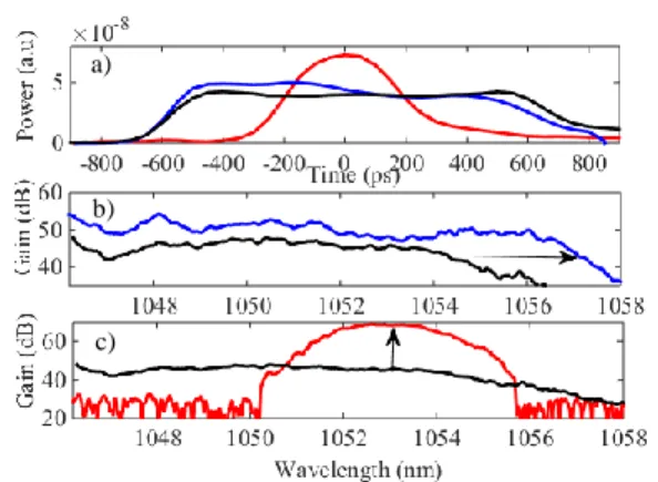
that the instantaneous power should be higher at around -200 ps (Fig. 6.a-blue line). In this case, the total energy is 1.07 µJ and is identical to the one used with the flat-top profile. Consequently, the gain has been extended to higher wavelength (Fig. 6.c-blue line) and the bandwidth is now increased by ~30 % from its initial value. This gain bandwidth improvement is a very interesting step forward to amplify an ultra-short pulse in a FOPA with a chirped signal [6]. Alternatively, the amplified signal can be injected in a laser chain. The required bandwidth is defined by the laser gain material. Therefore, the signal (from the FOPA) does not need to have a bandwidth considerably larger than the one from the laser amplifier. Thus, the pump can be temporally narrowed in order to get a higher peak power (for the same energy) and gain. For example, the gain bandwidth is reduced to 4 nm (Fig. 6.c-red line) by applying a bell shape in the pump profile with a temporal width of ~400 ps centered at 0 ps (Fig. 6.a-red line). The maximum gain centered at 1053 nm increases by 25 dB although we intentionally decrease the current of the last laser amplifier in order to avoid any damage. The energy is 0.7 µJ. The relevant gain can be measured between ~1050 and ~1056 nm. Outside this range, the pump pulse does not overlap with the signal spectrum, and thus no amplification can occur. The observed spectral signal corresponds to the fluorescence.
Fig. 5 (a) Amplified signal when a hole is applied in the pump temporal profile (inset). Delay=+200 ps (green), 0 ps (red), -200 ps (blue) (b) Spectral dip in the signal as a function of the time.
IV. CONCLUSION
We have investigated the shaping of parametric gain in a PCF thanks to the modification of the pump temporal profile. The local change of the power influences directly the instantaneous parametric gain. With this technique, we demonstrated the possibility to enhance or narrow the bandwidth by tuning locally the pump peak power at a specific time. This scheme can be implemented in front of a laser system to prepare or tune the spectrum of the seed. In addition, the shaping to a specific gain profile is easy and straightforward when the signal has a known and calibrated chirp.
REFERENCES
[1] J. Hansryd, P. A. Andrekson, M. Westlund, J. Lie, and P.-O. Hedekvist, “Fiber-based optical parametric amplifiers and their applications,” IEEE. J. Select. Topics Quantum Electron. 8, 506 (2002)
[2] M. E. Marhic, N. Kagi, T.-K. Chiang, and L. G. Kazovsky, “Broadband fiber optical parametric amplifiers,” Opt. Lett. 21, 573 (1996).
[3] M.-C. Ho, K. Uesaka, M. Marhic, Y. Akasaka, and L. G. Kasovky, “200-nm-bandwidth fiber optical amplifier combining parametric and Raman gain,” J. Lightwave Technol. 19, 977 (2011)
[4] T. Torounidis, P. A. Andrekson, B.-E. Olsson, “Fiber-optical parametric amplifier with 70-dB gain,” IEEE Photon. Technol. Lett. 18, 1194 (2006)
[5] P. L. Voss, R. Tang, and P. Kumar, “Measurement of the photon statistics and the noise figure of a fiber-optic parametric amplifier,” Opt. Lett. 28, 549 (2003)
[6] D. Bigourd, L. Lago, A. Mussot, A. Kudlinski, J.F. Gleyze, E. Hugonnot, “High-gain, optical-parametric, chirped-pulse amplification of femtosecond pulses at 1 µm,” Opt. Lett. 20, 3480 (2010)
[7] C. Fourcade-Dutin, Q. Bassery, D. Bigourd, A. Bendahmane, A. Kudlinski, , M. Douay, A. Mussot, “12 THz flat gain fiber optical parametric amplifiers with dispersion varying fibers,” Opt. Exp. 23, 10103 (2015)
[8] D. Bigourd, P. Beaure d’Augères, J. Dubertrand, E. Hugonnot, A. Mussot, “Ultra-broadband fiber optical parametric amplifier pumped by chirped pulses,” Opt. Lett. 39, 3782 (2014)
[9] C. Finot, S. Wabnitz, “Influence of the pump shape on the modulation instability process induced in a dispersion-oscillating fiber,” J. Opt. Soc. Am. B 32, 892 (2015)
[10] A. Vedadi, A. M. Ariaei, M. M. Jadidi, J. A. Salehi, “Theoretical study of high repetition rate short pulse generation with fiber optical parametric amplification,” J. Lightwave Technol. 30, 1263 (2012)
[11] F. Batysta, R. Antipenkov, T. Borger, A. Kissinger, J. T. Green, R. Kananavicius, G. Chériaux, D. Hidinger, J. Kolenda, E. Gaul, B. Rus, T. Ditmire, “Spectral pulse shaping of a 5 Hz, multi-joule, broadband optical parametric chirped pulse amplification frontend for 10 PW laser system,” Opt. Lett. 43, 3866 (2018)
[12] J. Moses, C. Manzoni, S.W. Huang, G. Cerullo, F. X. Kärtner, “Temporal optimization of ultrabroadband high-energy OPCPA,” Opt. Exp. 17, 5540 (2009)
[13] P. Delfyett, D. Mandridis, M. U. Piracha, D. Nguyen, K. Kim, S. Lee, “Chirped pulse laser sources and applications,” Progr. Quantum Electron. 36, 475 (2012)
[14] T. Wong, A. Lau, K. Ho, M. Tang, J. Robles, X. Wei, A. Chan, A. Tang, E. Lam, K. Wong, G. Chan, H. Shum, K. Tsia, “Asymmetric-detection time stretch optical microscopy (ATOM) for ultrafast high-contrast cellular imaging on flow,” Sc. Rep. 4, 3656 (2014)
[15] K. Mecseki, D. Bigourd, S. Patankar, N. H. Stuart,R. A. Smith, “Flat-top picosecond pulses generated by chirped spectral modulation from a Nd:YLF regenerative amplifier for pumping few-cycle optical parametric amplifiers,” Appl. Opt. 53, 2229 (2014)
[16] P. Morin, J. Dubertrand, P. Beaure d'Augères, Y. Quiquempois, G. Bouwmans, A. Mussot, E. Hugonnot, “µJ-level Raman-assisted fiber optical fiber parametric chirped pulse amplification,” Opt. Lett. 43, 4683 (2018) [17] K. Inoue, T. Mukai, “Signal wavelength dependence of gain saturation in a fiber optical parametric amplifier,” Opt. Lett. 26, 10 (2001)
[18] A.O.J. Wiberg, Z. Tong, E. Myslivets, N. Alic, S. Radic, “Idler Chirp Optimization in a pulse-pumped parametric amplifier” IEEE Photonics Society Summer Topical Meeting Series, TuD2.3 (2013)
[19] O Vanvincq, C Fourcade-Dutin, A Mussot, E Hugonnot, D Bigourd, “Ultrabroadband fiber optical parametric amplifiers pumped by chirped pulses. Part 1: analytical model” J. Opt. Soc. Am. B 32, 1479 (2015)
[20] C Fourcade-Dutin, O Vanvincq, A Mussot, E Hugonnot, D Bigourd, “Ultrabroadband fiber optical parametric amplifiers pumped by chirped pulses. Part 2: sub-30 fs pulse amplification at high gain” J. Opt. Soc. Am. B 32, 1488 (2015)
[21] G. Bouwmans, L. Bigot, Y. Quiquempois, F. Lopez, L. Provino, M. Douay, “Fabrication and characterization of an all-solid 2D photonic bandgap fiber with a low-loss region (<20 dB/km) around 1550 nm,” Opt. Exp. 13, 8452 (2005)
Fig. 6 (a) Flat top (black line), structured (blue line) and Gaussian profile (red line) of the pump (b-c) Corresponding spectral gain.
c)
a) b)