HAL Id: hal-02089775
https://hal.archives-ouvertes.fr/hal-02089775
Submitted on 24 Apr 2019
HAL is a multi-disciplinary open access
archive for the deposit and dissemination of
sci-entific research documents, whether they are
pub-lished or not. The documents may come from
teaching and research institutions in France or
L’archive ouverte pluridisciplinaire HAL, est
destinée au dépôt et à la diffusion de documents
scientifiques de niveau recherche, publiés ou non,
émanant des établissements d’enseignement et de
recherche français ou étrangers, des laboratoires
To cite this version:
David Navarro, Guilherme Migliato Marega. CLS : ContactLess Simulator. 12th International
Confer-ence on Wireless and Mobile Communications, Nov 2016, Barcelone, Spain. pp.65-69. �hal-02089775�
David Navarro, Guilherme Migliato-Marega
Université de Lyon, ECL, INSA Lyon, UCBL, CPE INL, UMR5270
F-69134, Ecully, France [email protected]
Abstract— A new simulator, ContactLess Simulator (CLS) has been developed in Visual C#. It is thus easy portable; several windows permit the user to configure the whole electronic system and to launch the simulation. It is specifically written to simulate contactless-powered smart systems, such as Near Field Communication (NFC) coupled to a microcontroller unit (MCU). More precisely, our study focuses on battery-less electronic systems: the MCU is supplied by the NFC circuit. To permit such a system to function, energy budget has to be explored; this is the aim of this simulator. This paper describes the considered electronic system, the models, and it details a simulation example. The simulated example is composed of a ST-Microelectronics M24LR04E NFC circuit and a Microchip PIC18LF2525 microcontroller.
Keywords-Simulation; Modeling; NFC; Microcontroller; MCU; Energy harvesting.
I. INTRODUCTION
New trends in energy-constrained electronic systems are to harvest energy in the environment and smartly manage energy. We consider 2 kinds of harvesting: natural and artificial energy sources harvesting. Natural sources are directly given by the Nature, such as vibration, temperature, or solar rays. Many electronic systems are developed to consider these energy sources, such as for example Seebeck systems or mini-photovoltaic panels [1]. Non natural sources include for example vibration (though piezoelectric elements [2]) ambient radiofrequency waves (through RF to DC converter), or magnetic fields such as wireless powering systems.
Wireless powering systems exist since several years, and are nowadays widespread in powerful systems, such as inductive charging stations for vehicles [3], smartphones wireless chargers [4], as well as lightweight systems, such as Near Field Communication (NFC) tags and emitter. We consider such lightweight systems that are highly energy constrained. Details on NFC are given in Section II.
We focus on easy to use and graphical simulator on NFC systems, more precisely on system-level energy aspects. Many simulators in NFC field exist. We do not consider Radiofrequency Identification (RFID) or NFC so-called "simulators" that are in reality hardware-based measurements systems (that we would call debuggers or emulators), such as [5]. Many simulators focus on physical link and radiofrequency propagation aspects [6], [7]. RFIDSIM [8] is
protocol. Others higher-level simulators focus on communication protocol and communication performance, such as NS-3 [9].
We propose in this paper a new simulator that considers energy harvesting from NFC emitter and energy balance according to the tag electrical consumption. The wireless-supplied tag is not only composed of a classical NFC circuit, but of a more complex smart system. It is described in Section II. Section III describes the models that were written in the simulator. Section IV details simulator graphical user interface, parameters, and an example result.
II. CONSIDERED NFC SYSTEM
A typical NFC system is composed of an emitter and a tag. It is shown in Fig. 1.
NFC systems use Low frequency (LF) from 125 KHz to 134 KHz, high Frequency (HF) at 13.56 MHz, or ultra high frequency (UHF) at 860 – 960 MHz. We consider the 13.56 MHz frequency communication that is mostly used in NFC systems [10]. Other frequencies will be supported in further releases of CLS simulator.
The emitter outputs a powerful signal in a coil (also called "antenna") at a specific frequency. The electromagnetic field carries power and data with the help from an Amplitude Shift Keying (ASK) modulated signal. Input power at receiver (tag) depends on signal strength at emitter, antennas gains, and distance between antennas. No simple exact equation exists since communication is near field. Friis equation, used in classical long range radiofrequency communications, is not valid. Indeed, Maxwell equations have to consider E and H fields. In our case, we use electrically small antennas thus near field limit distance d depends only on wavelength . It t is given as [11]:
d = More precisely, the NFC system we consider (13.56 MHz, few centimeters distance between emitter and tag) is in reactive (non-radiative) near field region. Fig. 2 shows this aspect. As a result, more simple equations are used to model signal attenuation due to distance.
Figure 1. Typical Architecture of NFC system [12].
Figure 2. Radiofrequency signal propagation [14]. Received power formulas are [13]:
PRX(E) = 6 4 2 .1 .1 . 1 d k d k d k (2) PRX(H) = 4 2 .1 . 1 d k d k (3) A tag is often composed of a NFC circuit that comprises 2 main blocks: energy harvesting block and data decoding block. The energy harvesting block converts the received electromagnetic field into usable energy in order to supply the circuit. The data decoding block demodulates the signal in order to recover the bit-stream. We consider in this study a smarter tag that comprises a microcontroller unit (MCU). This MCU controls the NFC circuit.
Novelty is that we focus on entire battery-less system. Neither NFC circuit nor MCU is externally supplied. The only energy source comes from electromagnetic field while NFC communications. To aim this, we choose the ST-Microelectronics M24LR04E chip. It is 13.56 MHz NFC ISO 15693 and ISO 18000-3 mode 1 compatible and it has an energy harvesting analog output that permits to supply other circuits on the board (i.e., MCU). The considered system is shown in Fig. 1, tag-side of the system is detailed in Fig. 3.
III. CLS MODELS
As it is shown in Section II, several circuits compose the system, so they have been modeled separately. Models are high-level (electronic system level), they have been written at C language level.
Figure 3. Considered battery-less tag. A. Emitter model
The emitter is modeled according to its emitting power, frequency, distance between emitter antenna and tag antenna. B. Antenna model
The emitter and tag antennas are PCB coil antennas in our prototype. Antenna gain is used to calculate propagation losses.
C. NFC circuit model
Several blocks in NFC circuit will be considered. RF2DC and DC2DC blocks are modeled. Performances are based on ST-Microelectronics M24LR04E circuit characteristics. D. MCU circuit model
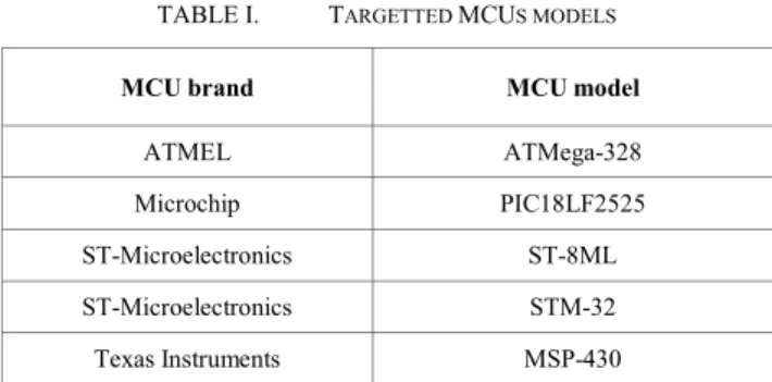
For this release, MCU is simply modeled as an electrical load. It requires a minimal voltage and consumes a nominal current. Power is calculated according to the MCU brand and model, oscillator type and operating frequency. Microchip PIC18LF2525 is modeled. Table I shows targeted MCUs.
TABLE I. TARGETTED MCUS MODELS
MCU brand MCU model ATMEL ATMega-328 Microchip PIC18LF2525 ST-Microelectronics ST-8ML ST-Microelectronics STM-32 Texas Instruments MSP-430
ATMEL, ST-Microelectronics and Texas Instruments models are under development and will be released soon.
IV. SIMULATOR & GRAPHICAL USER INTERFACE The CLS simulator has been written in Visual C# in order to be easily portable on Microsoft 64-bit Windows operating systems. It is part of the Visual Studio Community, a free tool for academic research [15].
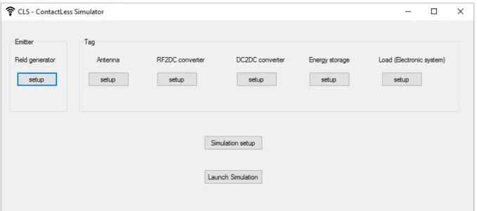
Graphical user interface is drawn in a horizontal way, from Emitter on the left towards Load (Electronic system) on the right. Fig. 4 shows the main window of CLS simulator. Architecture presented Section II (Fig. 1) is recognizable. Each Element has to be setup before simulation is run.
Figure 5. Electromagnetic field parameters at Emitter A. Tag antenna
The tag antenna parameter is the gain (in dBi). At tag antenna output, the received electromagnetic field is known. More precisely the received power is known according to all above parameters; signal attenuation due to propagation is calculated. According to (2) and (3), as communication is near field, power of magnetic field decays as the inverse sixth power of distance [16]. Such a model is used.
B. Tag RF2DC converter and DC2DC converter The RF2DC and DC2DC converters efficiencies (in %) are expressed in these windows. Efficiencies can alternatively be replaced by a transfer function to match a realistic circuit. In our example, we choose this option and we set equations from ST-Microelectronics M24LR04E datasheet.
Figure 6. Energy storage parameters C. Energy storage
The energy storage parameters are used to calculate the amount of energy that can be saved in a switched capacitor, used as a super-capacitor. Parameters are capacitance value (in nF) and total leakages (in fA) of switches and capacitor (Fig.6).
The role of this module is to further simulate energy storage versus energy usage durations. It will lead to an energy budget analysis.
D. Load (electronic system)
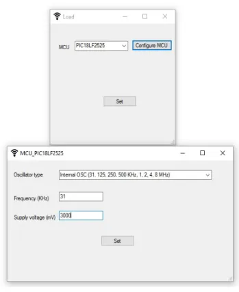
For this simulator release, the load is a MCU (microcontroller unit). When a MCU is chosen, the "Configure MCU" button opens a new window. Oscillator type is entered.
Figure 7. Load (electronic system) parameters
For this example, Microchip PIC18LF2525, it can be external RC (up to 4 MHz), external XTAL (crystal oscillator, up to 40 MHz), and internal OSC (from the internal 8MHz source or the INTRC 31KHz source, several frequencies are available according to frequency post-scaler). Frequency (in KHz) and supply voltage are then entered. All these parameters are taken from Microchip PIC18LF2525 datasheet; from current voltage versus frequency, current versus voltage and current versus frequency curves. User can enter the supply voltage he would like to obtain from the energy harvesting block. This field is dedicated to future features.
E. Simulation setup
The simulation setup permits to configure a simulation time and a simulation step for transient analysis. These parameters will be used in future release, for the moment, only static simulations are run.
F. Launch simulation & result window
In main window, Launch simulation button is pressed to simulate the system that user has configured. All data are calculated and written in several output files, and graphical results are displayed on a window. This window is automatically opened. Static results in Fig. 8 are obtained for parameters in table II.
Figure 8. Result window.
TABLE II. PARAMETERS USED FOR TEST EXAMPLE
Emitting power 30 mW Frequency 13560 MHz
Distance 1 cm Antennas gain (Emitter & tag) -1 dBi
RF2DC & DC2DC converters Equations from M24LR04E Switches leakages 100 fA MCU brand/model Microchip/PIC18LF2525
MCU Oscillator Internal OSC, 31KHz MCU Voltage 2V to 5.5V
With the help from Fig. 8, generated current from energy harvesting circuit can be compared to required current from MCU; generated voltage can be compared to minimal supply voltage of the MCU.
V. CONCLUSION
We presented first release of CLS: ContactLess Simulator. It permits to configure a NFC system: emitter and tag. Tag is battery-less (self supplied), it comprises an energy harvesting module and a microcontroller unit (MCU). CLS was developed with Microsoft Visual C#, its graphical interface is fully based on windows where parameters are set. A launch button runs the simulation and displays a result window. For this release, a static simulation is run and displays the harvested power (voltage and current) and the required power (voltage and current) for the MCU. Further releases will support transient analysis, energy calculation, and more electronic circuits in library.
[2] W. S. Wang, W. Magnin, N. Wang, M. Hayes, B. O'Flynn, C. O'Mathuna, "Bulk Material Based Thermoelectric Energy Harvesting for Wireless Sensor, Applications", Sensors & their Applications XVI, IOP Publishing, Journal of Physics : Conference, Series 307, pp. 1-6, 2001
[3] U. K. Madawala, D. J. Thrimawithana, " A Bidirectional Inductive Power Interface for Electric Vehicles in V2G Systems", IEEE Transactions on Industrial Electronics, Volume: 58, Issue: 10, pp 4789–4796, 2011, doi: 10.1109/TIE.2011.2114312.
[4] R. Tseng, B. von Novak, S. Shevde, and K. A. Grajski, "Introduction to the alliance for wireless power loosely-coupled wireless power transfer system specification version 1.0", Wireless Power Transfer (WPT) Conference, pp. 79-83, 2013, doi: 10.1109/WPT.2013.6556887.
[5] C. Angerer, B.Knerr, M.Holzer, A.Adalan, and M. Rupp, "Flexible simulation and prototyping for RFID designs", EURASIP Workshop on RFID Technology, pp.51-54, 2007.
[6] T. Cheng, L. Jin, "Analysis and Simulation of RFID Anti-collision Algorithms", International Conference on Advanced Communication Technology, volume 1, pp 697-701, 2007.
[7] J. Wang, D. Yang, "Design of a Multi-Protocol RFID Tag Simulation Platform Based on Supply Chain", International Conference on Management and Service Science (MASS), pp.1-4, 2009.
Communication, and Networking - Workshops (SECON), pp. 1-6, 2015, doi: 10.1109/SECONW.2015.7328143.
[10] ATMEL, "Understanding the Requirements of ISO/IEC 14443 for Type B Proximity Contactless Identification Cards", Application Note, [Online, retrieved: 15th July 2016].
Available from: http://www.atmel.com/images/doc2056.pdf.
[11] P. V. Nikitin, K. V. S. Rao, and S. Lazar, "An Overview of Near Field UHF RFID", International Conference on RFID, pp. 1-8, 2007, doi: 10.1109/RFID.2007.346165.
[12] G. Proehl, "An Introduction to Near Field Communications", ST-Microelectronics [Online, retrieved: 15th July 2016].
Available from:
http://www.st.com/content/st_com/en/applications/connectivit y/near-field-communication-nfc.html
[13] RF Memories and Transceivers, STMicroelectronics
[14] H. G. Schantz, "Near field propagation law & a novel fundamental limit to antenna gain versus size", Antennas and Propagation International Symposium, pp 237-240, 2005, doi: 10.1109/APS.2005.1552223.
[15] G. M. Djuknic, "Method of measuring a pattern of electromagnetic radiation", US Patent 6657596-B2, 2003.
[16] Microsoft, "Visual Studio Community", [Online, retrieved:
15th July 2016]. Available from:
https://www.visualstudio.com/en-us/products/visual-studio-community-vs.aspx.
[17] J. I. Agbinya, "Investigation of Near Field Inductive Communication System Models, Channels and Experiments", Progress In Electromagnetics Research B, Vol. 49, 129-153, 2013.