HAL Id: inria-00131002
https://hal.inria.fr/inria-00131002v2
Submitted on 16 Feb 2007
HAL is a multi-disciplinary open access
archive for the deposit and dissemination of
sci-entific research documents, whether they are
pub-lished or not. The documents may come from
teaching and research institutions in France or
L’archive ouverte pluridisciplinaire HAL, est
destinée au dépôt et à la diffusion de documents
scientifiques de niveau recherche, publiés ou non,
émanant des établissements d’enseignement et de
recherche français ou étrangers, des laboratoires
LDPC-Staircase Erasure Correction Codes
Mathieu Cunche, Vincent Roca
To cite this version:
Mathieu Cunche, Vincent Roca. Adding Integrity Verification Capabilities to the LDPC-Staircase
Erasure Correction Codes. [Research Report] RR-6125, INRIA. 2007, pp.22. �inria-00131002v2�
a p p o r t
d e r e c h e r c h e
ISRN
INRIA/RR--6125--FR+ENG
Thème COM
Adding Integrity Verification Capabilities to the
LDPC-Staircase Erasure Correction Codes
Mathieu CUNCHE — Vincent ROCA
N° 6125
LDPC-Staircase Erasure Correction Codes
Mathieu CUNCHE , Vincent ROCA
Th`eme COM — Syst`emes communicants Projet Plan`ete
Rapport de recherche n 6125 — February 2007 — 22 pages
Abstract: With the advent of broadcast/multicast systems, like DVB-H, large scale content broad-casting is becoming a key technology. This type of data distribution scheme largely relies on the use of Application Level Forward Error Correction codes (AL-FEC), not only to recover from erasures but also to improve the content broadcasting scheme itself (e.g. FLUTE/ALC). This work focuses on the LDPC-staircase large block FEC codes that are well suited to these services, and for which an open source codec is available.
We believe that sooner or later these broadcasting systems will require security services. Therefore, the current work focuses on the content integrity service, which is one of the key security building blocks. More and more often (and in particular in the context of DVB-H), the client terminal will be a handheld autonomous device with limited battery capacity. In order to save the client terminal resources, we have focused on a hybrid system that merges the FEC decoding and content integrity verification services. This hybrid system takes advantage of a corruption propagation phenomenon during the FEC decoding process in order to perform integrity verification. Thanks to this approach, we have been able to design a high performance hybrid codec that keeps the same erasure recovery capabilities of the LDPC-staircase codes while providing a Content Integrity Verification service almost for free. More precisely this system can detect an object corruption triggered by deliberate attacks or by transmission errors (not detected by lower layer protocols) with a very high probability (close to 100%) with a processing overhead that is only a minimal fraction (around 6.2%) of the overhead of a hash calculation over the whole object, which is the usual way to address the problem.
Finally, we explain how to extend this system in order to provide a 100% detection guarantee, or how this system can help to mitigate a Denial of Service attack.
Correcteurs d’Effacements LDPC-Staircase
R´esum´e : Avec l’arriv´ee de syst`emes tels que le DVB-H, la diffusion de contenus `a tr`es large ´echelle est devenue une technologie clef. Ce type de distribution de donn´ees repose largement sur l’utilisation de codes correcteurs d’erreurs de niveau applicatif (ou AL-FEC), non seulement afin de corriger des effacements de paquets, mais aussi afin d’am´eliorer le syst`eme de de diffusion lui mˆeme (par exemple FLUTE/ALC). Ce travail s’int´eresse aux codes FEC grand bloc LDPC-staircase qui sont bien adapt´es `a ces services et pour lesquels existe un codec open-source.
De plus nous pensons que tˆot ou tard, ces syst`emes de diffusion auront besoin de services de s´ecurit´e. Par cons´equent, nos travaux se sont focalis´es sur le service de v´erification d’int´egrit´e du contenu transmis, qui est l’une des briques de s´ecurit´e fondamentales.
De plus en plus (et en particulier dans un contexte DVB-H) le terminal client sera un ´equipement portable autonome, disposant de resources ´energ´etiques limit´ees. Afin de pr´eserver les ressources de ces terminaux, nous avons ´etudi´e un syst`eme hybride qui fusionne les services de d´ecodage FEC et de v´erification d’int´egrit´e du contenu. Ce syst`eme hybride tire partie d’un ph´enom`ene de propagation de corruptions durant le d´ecodage FEC pour effectuer la v´erification d’int´egrit´e. Grace `a cette approche, nous avons ´et´e en mesure de concevoir un codec hybride hautes performances qui conserve les capacit´es de correction d’effacements de paquets des codes LDPC-staircase tout en fournissant, quasiment gra-tuitement, un service de v´erification d’int´egrit´e du contenu. Plus pr´ecisement ce syst`eme peut d´etecter une corruption du contenu suite `a une attaque d´elib´er´ee ou `a une erreur de transmission (non d´etect´ee par les couches protocolaires basses) avec une tr`es forte probabilit´e (proche de 100%) et un surcroit de traitement qui ne repr´esente qu’une tr`es faible fraction (environ 6.2%) du calcul d’un hash complet sur l’ensemble du contenu, qui est la fa¸con habituelle de proc´eder.
Enfin nous montrons comment ´etendre ce syst`eme pour offrir une garantie de d´etection de 100%, ou comment ce syst`eme peut aider `a att´enuer les effets d’une attaque par d´eni de service.
Contents
1 Introduction 4
1.1 Context of this Work . . . 4
1.2 On the Use of Packet Erasure AL-FEC Codes . . . 4
1.3 The LDPC-Staircase AL-FEC Codes . . . 5
1.4 Adding Content Integrity Checks and Source Authentication to Broadcasting Systems . . 5
1.5 Goals of this Work . . . 6
2 Introduction to LDPC-Staircase Codes 6 2.1 Parity Check Matrix . . . 6
2.2 Encoding Process . . . 7
2.3 Decoding Process . . . 7
3 Problem Analysis and Observation 7 3.1 The Attack Model . . . 7
3.2 The Corruption Propagation Phenomenon . . . 8
3.2.1 The Phenomenon . . . 8
3.2.2 Experimental Approach . . . 8
3.3 First Conclusions . . . 9
3.3.1 The Attacker’s Point of View . . . 9
3.3.2 The Receiver’s Point of View . . . 9
4 Our Solution: VeriFEC 10 4.1 VeriFEC Principles . . . 10
4.2 On the Sender Side . . . 10
4.3 On the Receiver Side . . . 11
4.4 On False-Positive and False-Negatives . . . 11
5 Performance Evaluation 11 5.1 Dependency W.R.T. the Verification Ratio . . . 11
5.2 Computing Overhead Gains . . . 12
5.3 Dependency W.R.T. the Object Size . . . 13
5.4 Dependency W.R.T. the FEC Coding Rate . . . 14
6 Additional Attacks and Counter-Measures 14 6.1 Corruption of a Weak Symbol . . . 15
6.2 Modification of the Packet Stream . . . 17
7 Making VeriFEC 100% Safe 17 7.1 Adding a Hash over the Whole Object . . . 18
7.2 The Solution: Adding a Complementary Check to VeriFEC . . . 18
7.3 Application . . . 19
8 Related works 20
1
Introduction
1.1
Context of this Work
This work focuses on large scale content broadcasting systems. The ”IP Datacast” (IPDC) service of DVB [2] and the ”Multimedia Broadcast/Multicast Service” (MBMS) of 3GPP [1] are good examples of such broadcasting systems. Some of them rely on terrestrial base stations (e.g. DVB-H) while others rely on satellite transmissions, or on hybrid terrestrial/satellite solutions (e.g. DVB-SH). All these systems are characterized by the fact that there is no back channel. This feature enables an unlimited scalability in terms of number of receivers, which is one of the key targets. But it also means that no repeat request mechanism can be used that would enable the source to adapt its transmission according to the feedback information sent by the receivers, and in particular to retransmit lost information.
The content that is broadcast is potentially extremely heterogeneous. Let’s take the example of a popular event like the Olympic Games. The content broadcast includes live audio and video, the results updated in real-time, recorded interviews or sport events, timetables of upcoming events, and last but not least the guides of the available programs/contents, also known as Electronic Service Guides (ESG). If the live audio and video contents are streamed on the TV channels, the other contents can be seen as objects, and are sent using a reliable file delivery approach. Because of the popularity of the Olympic Games, there will be potentially millions of clients accessing the same content at the same time, which makes broadcasting technologies well suited.
In our work, we will focus on the transmission of objects rather than on audio/video streaming. There-fore the transmission latency has little importance and we will not consider the potential impacts of the transmission schemes (including the use of FEC codes) on the decoding latency at a receiver.
The key technologies to build the scalable content broadcasting system are the ALC reliable multicast transport protocol [8] and the FLUTE file delivery application that relies on ALC [13]. Both of them have been designed at IETF and have been included in the 3GPP/MBMS and DVB/IPDC services. Since there is no real-time constraint, transmissions usually follow a carousel approach. More specifically, the content is transmitted continuously for a total duration that significantly exceeds the minimum time to download the content. Therefore, a receiver that experiences an intermittent connectivity can still download the content, even if this requires to get packets from several carousel transmission cycles.
1.2
On the Use of Packet Erasure AL-FEC Codes
For efficiency purposes, file delivery systems largely rely on the use of Forward Error Correction codes running at the Application Layer (or AL-FEC). The AL-FEC building block is therefore a major com-ponent of the FLUTE/ALC protocol stack. Since AL-FEC operates at application level, the channel is a packet erasure channel. It means that packets either arrive at a receiver, without any error, or are lost (erased). For instance a packet can be lost because of transmission problems (that exceed the error correcting capabilities of the codes that operate at the physical layer), or because of congestion problems within an IP router, or simply because the mobile device is disconnected (e.g. mobile receivers will often experience an intermittent connectivity).
After an FEC encoding of the file, redundant data is transmitted along with the original data. Thanks to this redundancy, up to a certain number of missing packets can be recovered at the receiver. AL-FEC features a great superiority compared to AL-FEC schemes that operate at the physical layer for file broadcasting systems: (1) indeed AL-FEC encoding is potentially performed over the whole file (e.g. the LDPC-staircase AL-FEC codes considered can encode objects of several hundreds of megabytes in a single pass, see section 1.3). This feature warrants good robustness, even in case of long loss periods. (2) AL-FEC encoding also offers significant performance benefits with mobile receivers that experience an intermittent connectivity. From this point of view, AL-FEC is a perfect companion to the carousel transmission scheme mentioned earlier. Finally (3) since AL-FEC encoding is performed dynamically, the coding rate (i.e. the ratio between the source information to the source plus parity information) can be
adjusted on a per-object basis, just on time, rather than being a fixed, predefined value. Therefore more important objects can benefit from a more robust transmission thanks to a lower coding rate. Some AL-FEC codes, in particular Raptor codes[10], even enable new parity symbols to be produced dynamically, as needed, for a given object. In that case there is no predefined coding-rate for the object, and an unlimited number of parity symbols can be produced (in practice this number is limited in particular by the finite symbol identified field in the ALC packet).
These benefits do not apply to physical level FEC codes that have limited correction capabilities and offer no flexibility. This is due to the fact they must accommodate any kind of traffic, and in particular they must not impose excessive latency on real-time data flows. This constraint requires to operate on small, fixed size, blocks, with a predefined coding rate.
1.3
The LDPC-Staircase AL-FEC Codes
Several AL-FEC codes exist. The LDPC-staircase [11] codes are particularly interesting for file delivery systems, as shown in [19]. These codes are variants of the well known LDPC codes introduced by Gallager in the 1960s [6]. But unlike the original proposal, thanks to an appropriate parity check matrix structure, the LDPC-staircase codes feature a high encoding/decoding speed.
The LDPC-staircase codes belong to the class of large block codes, which means they can easily operate on blocks that are composed of a huge number of source symbols (typically several 100,000s). If each symbol is 1 kilobyte long, then a file of several hundreds of megabytes can be FEC encoded in a single pass. This is a great advantage over so called small-block FEC codes, like the popular Reed-Solomon codes, that can also work over a packet erasure channel [15]. Because Reed-Solomon codes are limited to small blocks (composed of a few tens of source symbols), they offer a smaller erasure protection than LDPC codes. The interested reader can find detailed performance comparisons in our previous work [19][12].
The remaining of this work is based on the LDPC-staircase AL-FEC codes. No other LDPC codes will be considered, because LDPC-staircase codes are already known to yield good performance[19], an on-the-shelf GNU/LGPL codec is available [21], and these codes are currently being standardized at IETF [20].
1.4
Adding Content Integrity Checks and Source Authentication to
Broad-casting Systems
In the current DVB-H specifications, there is no file download security service specified (we are not considering here DRM aspects). This is probably not a big issue within closed networks (like the DVB-H broadcasting infrastructure) where launching a DoS attack or injecting spurious traffic requires an expensive equipment. But the situation is opposite in case of open networks that include transmissions over the Internet or Wifi hotspots for instance.
In that case, one of the basic security services that will be required are the content integrity and source authentication. These services enable a receiver to be sure that what he received is actually the content that has been sent by the authorized sender.
These integrity/source verifications can be made either on a per-packet basis, or on a per-object basis. Concerning the per-packet approach, packet integrity and packet source authentication can be provided with Message Authentication Codes (MAC) [3][22]. But using a MAC requires that the sender and the receiver share a secrete key, which may be difficult to achieve in a multi-receiver configuration. Packet integrity and packet source authentication can also be provided with digital packet signatures [14]. Since digital signatures rely on asymmetric cryptography to sign the hash of the packet, there is no need for a shared secret since the public key is used to check the signature. But asymmetric cryptography is several orders of magnitude slower than symmetric cryptography, which prevents its use on high data rate flows. The TESLA packet authentication scheme is a third alternative, that is well suited to high data rate broadcasting over lossy channels. In particular an instantiation of the TESLA scheme is currently being
specified for FLUTE/ALC content broadcasting [17]. But this approach does not come without penalties, in particular because it generates a transmission overhead and delays integrity verifications.
Concerning the per-object approach, the traditional solution consists in signing a hash of the object with an asymmetric cryptographic function. In that case, with big objects, the computation time of the signature is low compared to the hash calculation over the object. This is all the more true as a modern, strengthened hash function must be used. Indeed, older hash functions like MD5 do not offer sufficient protection anymore, and even if they are faster, they are progressively banned from secure systems. This per-object solution, based on a signed hash of the whole object, will be the reference solution against which we will compare the scheme introduced in this work.
In practice, other security services will probably be required, like the need to control who can access the content that is broadcast (e.g. by using content encryption). However these services are out of the scope of the current work.
1.5
Goals of this Work
Our work explores an alternative way of checking the integrity of a received content. More specifically, the goal of our work is to add data verification capabilities to an existing FEC scheme, while minimizing the computation and transmission overheads. The resulting system, that we will call VeriFEC in this paper, must be able to detect a potential corruption of the decoded object with a very high probability, while keeping exactly the same erasure recovery capabilities as the original AL-FEC scheme. The corruption can be either intentional (i.e. mounted by an intelligent attacker) or not (e.g. caused by transmission errors that have been detected but not corrected by the physical layer FEC codes/CRC).
In the remaining of this paper, we first introduce the LDPC-staircase AL-FEC codes. We then discuss the corruption propagation algorithm that is at the basis of the VeriFEC scheme. Section 4 details our proposal and section 5 gives an account of the performance experiments. Then we explain how to prevent some (intelligent) attacks. Section 7 details an approach to go beyond the 99.86% corruption detection capabilities of VeriFEC. We then introduce related works and we conclude.
2
Introduction to LDPC-Staircase Codes
This section introduces LDPC-staircase codes that are the foundations of the VeriFEC proposal. The interested reader will find a more detailed description in [19][20].
2.1
Parity Check Matrix
LDPC codes in general rely on a dedicated matrix, H, called a ”Parity Check Matrix”, at the encoding and decoding ends. This parity check matrix defines relationships (or constraints) between the vari-ous encoding symbols (i.e. source symbols and parity symbols), that are later used by the decoder to reconstruct the original k source symbols if some of them are missing.
The LDPC-staircase parity check matrix, H, can be divided into two parts:
the left side of the matrix, of size (n−k)×k, defines in which equations (i.e. rows) the source symbols (i.e. columns) are involved. More precisely, each source symbol is involved in three equations, chosen so that each equation includes at least two source symbols. Depending on the coding rate, some equations will not include two source symbols after this process. In that case, additional source symbol(s) will be chosen randomly, as explained in [20].
the right side of the matrix, of size (n − k) × (n − k), defines in which equations the parity symbols are involved. With LDPC-staircase codes, this sub-matrix is a “staircase matrix” (a.k.a. double diagonal).
2.2
Encoding Process
Thanks to the staircase matrix, parity symbol creation is straightforward: each parity symbol is equal to the byte-per-byte XOR sum of all source symbols in the associated equation, plus the previous parity symbol (except for the first parity symbol). Therefore encoding must follow the natural parity symbol order, starting with the first parity symbol.
2.3
Decoding Process
As explained before, in this paper we will only focus on AL-FEC codes, i.e. codes that operate at application level, over a packet erasure channel (section 1.2). This feature greatly simplifies the decoding algorithm that can follow a simple approach as we now explain.
Decoding basically consists in solving a system of n − k linear equations whose variables are the n source and parity symbols. Of course, the final goal is to recover the value of the k source symbols only. Many decoding techniques are possible. One of them is the following trivial algorithm [20]: given a set of linear equations, if one of them has only one remaining unknown variable, then the value of this variable is that of the constant term. So, replace this variable by its value in all the remaining linear equations and reiterate. The value of several variables can therefore be found recursively. Applied to LDPC FEC codes working over an erasure channel, the parity check matrix defines a set of linear equations whose variables are the source symbols and parity symbols. Receiving or decoding a symbol is equivalent to finding the value of a variable. During all these operations, only byte-per-byte XOR operations are performed over the various symbols, which makes high speed decoding possible.
The Gaussian elimination technique (or any optimized derivative) is another possible decoding tech-nique. Hybrid solutions that start by using the trivial algorithm above until a given criteria is reached (e.g. the number of non duplicated symbols received and/or decoded is above a given threshold) and finish with a Gaussian elimination of the simplified system are also possible. However in the current paper we will only consider the trivial algorithm sketched above, which is also the one available in the reference LDPC-staircase codec.
3
Problem Analysis and Observation
This section introduces the attack model and the corruption propagation phenomenon that is at the basis of our proposal. Then we draw some conclusions on the potential use of this phenomenon, both from the attacker point of view and from the receiver point of view.
3.1
The Attack Model
We assume that an object is transmitted from a sender to a remote receiver over an unsecured channel. We further assume that there is an intelligent and powerful attacker in this channel. This attacker has the full control of the unsecured channel and can potentially:
intercept all the packets sent by the sender; delay, reorder and delete these packets; send chosen, forged packets to the receiver.
A first goal of the attacker can be to corrupt as many transmitted objects as possible, in order to mount a Denial of Service (DoS) attack. This attack is trivial to launch since the attacker can corrupt all packets sent to the receiver (in practice corrupting a subset of them is sufficient). The challenge for the receiver is to quickly identify corrupted objects and to get rid of them, with the lowest possible computational overhead.
Another goal of the attacker can be to corrupt the transmitted object without the receiver’s knowing. For instance, the attacker may want to change some bytes of the object in order to add a back-door or virus. The challenge for the receiver is to identify with highest possible probability that an object has been corrupted. Ideally, there should not be any false negative (i.e. non detected corrupted objects) nor false positive (i.e. objects declared as corrupted when this is not the case).
Even if we primarily consider intelligent attackers, the attack might also be non-intentional. For instance, it might be caused by transmission errors that have not been detected and/or corrected by the physical layer FEC codes/CRC. Even though it is usually considered that these corruptions are rather infrequent, they are not totally impossible, especially in some harsh wireless environments. In our work, we consider that non-intentional attacks are special cases of the attack model, and the challenge here is to detect the corruption, even when a very small number of bytes are corrupted in the object.
The remaining of the paper will essentially focus on the second attack (the attacker tries to corrupt the transmitted object without the receiver’s knowing) which is the most difficult problem. We will then show that the first kind of attack (DoS) is also addressed by the solution.
3.2
The Corruption Propagation Phenomenon
3.2.1 The Phenomenon
In order to recover from packet erasures, the FEC decoder rebuilds the missing data with the received data and parity symbols, in a recursive way, as explained in section 2.3.
Let us now consider the following constraint equation: S0⊕ S1⊕ S2⊕ S3= 0
We assume that the value s1, s2, s3of the symbols S1, S2, S3 have been received but not s0. Then:
s0= s1⊕ s2⊕ s3
Assume that an attack has been launched and that the received value of symbol S3is the corrupted value
s0
3, such that: s03= s3⊕ ε. The decoded value of symbol S0 will be:
s1⊕ s2⊕ s03= s1⊕ s2⊕ s3⊕ ε = s0⊕ ε = s00
which has inherited the corruption of S3. Therefore, if a corrupted symbol is used in a decoding operation,
the decoded symbol inherits from the corruption. Since a source (resp. parity) symbol is present in 3 (resp. 2) constraint equations, the corruption can directly spread to 3 (resp. 2) other symbols. Furthermore, each newly decoded symbol can be used to decode other symbols recursively, so an avalanche of corruptions can happen during decoding. We call this the corruption propagation phenomenon.
3.2.2 Experimental Approach
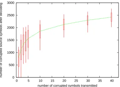
In order to analyze the importance of this propagation phenomenon, we have carried out experiments using the on-the-shelf LDPC-staircase C++ reference codec [21]. We chose an object composed of 20, 000 symbols1
. A coding rate of 2/3 is used: to the k = 20, 000 source symbols, n − k = 10, 000 parity symbols are added, so that k/n = 2/3. Symbols are transmitted in a random order (we justify this choice later on, in section 6.1). The attacker chooses randomly a given number of symbols and corrupts them. Given this number of corrupted symbols, the experiments consist in counting the number of corrupted source symbols in the decoded object. Note that we do not take into account the number of parity symbols corrupted after decoding, but only the number of source symbols corrupted. Indeed, the ultimate goal of the attacker is to corrupt the object, not the temporary (parity) symbols used during decoding. The test is repeated 2000 times for each value on the X-axis, and we plot the minimum/average/maximum/90% confidence intervals.
1
The size of each symbol does not influence the propagation phenomenon and therefore it is not specified here. Later on, when measuring the computation overhead of the various alternatives, a symbol size of 1024 bytes will be used.
0 500 1000 1500 2000 2500 3000 0 5 10 15 20 25 30 35 40
number of corrupted source symbols after decoding
number of corrupted symbols transmitted
Figure 1: Number of corrupted source symbols after decoding (average/min/max/90 % confidence inter-val) W.R.T. the number of corrupted symbols received.
Figure 1 shows that even a single corruption causes on average more than 700 corrupted symbols after decoding (i.e. 3.5% of the object).
At the same time, some experiments show few symbol corruptions after decoding. This means that some symbols are used to rebuild only a small number of symbols during decoding. In some tests there is no corrupted symbols at all after decoding. It means that the symbol corrupted by the attacker is a parity symbol that has not been used during decoding (because all the symbols of the equations containing this parity symbol were already received or decoded). In that case, from the attacker’s point of view, the attack fails.
3.3
First Conclusions
3.3.1 The Attacker’s Point of View
We have seen that the corruption of a single symbol can cause the corruption of many symbols after decoding. Said differently, a massive corruption of the object can be achieved with only a partial attack over the transmitted data. As a side effect, the attacker will usually have difficulties to create a limited, targeted, corruption in the decoded object. This is not totally impossible though, since some (rare) tests exhibit a small number of corrupted decoded symbols. We will discuss this aspect in details in section 6.1. 3.3.2 The Receiver’s Point of View
From the receiver’s point of view the important corruption propagation phenomenon can be seen either as a problem (e.g. in case of a recorded video file, playing the decoded file will exhibit many glitches) or as an advantage (detecting a corruption is easier).
In our case, we decided to take advantage of this phenomenon to design a statistical verification system, whereby we check the integrity of a subset of the decoded object only in order to reduce the computation overheads.
4
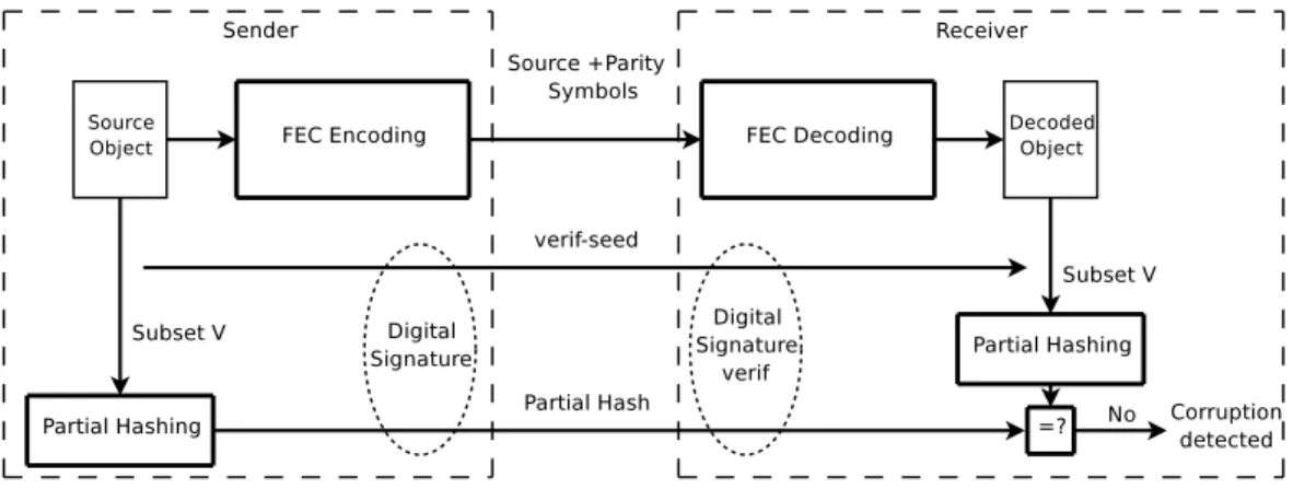
Our Solution: VeriFEC
This section introduces the VeriFEC hybrid scheme that merges an LDPC-staircase AL-FEC scheme and a content integrity verification scheme into the same building block.
4.1
VeriFEC Principles
The main idea of this system is to check only a subset of the symbols after decoding of the object in order to detect an attack that might have occurred during transmission. Thanks to the corruption propagation phenomenon we know that most attacks, even on a single symbol (this is the worst case from a corruption detection point of view), will trigger many corruptions in the decoded object. Therefore, by checking only a subset of the source symbols after decoding we can detect corruption attacks with a high probability. Even if we cannot reach a 100% dectection probability (since we only check a subset of the object), we will show in section 5 that in practice the vast majority of corruptions are detected.
Figure 2: VeriFEC principles.
In the remaining of the paper we will illustrate the discussion with a single receiver. However VeriFEC does not include any mechanism that would limit its field of application to a single receiver. On the opposite, since there is no information sent by the receiver(s) to the sender, the VeriFEC proposal is massively scalable.
4.2
On the Sender Side
First of all, the sender performs FEC encoding and sends the source and parity symbols as usual. In parallel, the sender randomly selects a subset V of Nverifsource symbols, by using a pseudo-random
number generator and a seed, verif seed. Then it computes the hash of this subset, called partial hash. The {verif seed; partial hash} tuple can then be sent to the receiver. Since the security of this tuple is crucial for whole scheme, we can imagine that a secure channel exists between the sender and the receiver, over which the sender can safely transmit this tuple. If not, the sender signs this tuple using a digital signature [14] in order to prevent an attacker from forging the verification tuple. The signed verification tuple can then be sent in-band on the unsecured data channel, or sent out of band to the receiver by any means (e.g. stored in a web page).
Note that in the general case (no secure channel), the {verif seed; partial hash} tuple is not hidden to the attacker. This latter can therefore determine the V subset of source symbols. This is not an issue, as we will show in Section 6.1.
4.3
On the Receiver Side
First of all, the receiver proceeds to a standard AL-FEC decoding of the object, using the received symbols.
Then the receiver must retrieve the {verif seed; partial hash} tuple (and check the signature if this tuple was not sent over a secure channel). The receiver can now proceed to the integrity verification. Thanks to the received verif seed, the receiver selects the same subset V of source symbols. Then the hash of this subset is computed and compared to the received partial hash. If the two hashes are different, the receiver can say for sure that a corruption has been detected. Otherwise the receiver cannot conclude that the decoded object is not corrupted.
4.4
On False-Positive and False-Negatives
We have just seen that false-negative results (i.e. non detected corrupted objects) may take place. In that case, the partial hash has “missed” the corrupted source symbol(s), probably because the initial corruption has not been propagated significantly by the FEC decoding process. So the attack succeeded (we will see in section 7 how to address this problem if need be).
But VeriFEC never gives false positive results (i.e. say that an object is corrupted when this is not the case). Indeed, if the two partial hashes differ, it means that at least one bit of the verified subset V has been modified and therefore that an attack occurred.
To summarize VeriFEC has a small probability of false-negative results (as we will show in section 5) but never gives false-positive answers.
5
Performance Evaluation
We have designed a VeriFEC class, that derives from the underlying LDPCFecSession class of the LDPC-staircase C++ open source codec version 2.0 [21]. The VeriFEC class relies on the OpenSSL version 0.9.8c library for the cryptographic primitives. More precisely it uses RSA-1024 for digital signatures, and the message digest scheme is one of MD5, RIPEMD-160 [5], SHA-1, or SHA-256. We believe that SHA-256 (and to a lesser extent RIPEMD-160 and SHA-1) is representative of new, strengthened hash functions that are expected to be secure for the next ten years or more. Older hash functions, like MD5, do not offer sufficient protection anymore. Even if they are faster, they are progressively banned from secure systems.
With this VeriFEC codec, we carried out experiments meant to appreciate its performances from a corruption detection point of view and processing performance point of view. We also carried out experiments to analyze the impacts of various VeriFEC parameters on performances.
Unless otherwise mentioned, the same configuration as that of section 3.2.2 is used: the object is composed of k = 20, 000 symbols (except in section 5.3), the coding rate is equal to 2/3 (except in section 5.4) which means that n − k = 10, 000 parity symbols are added. In all cases, the source and parity symbols are sent in a random order (we justify this choice later on, in section 6.1).
During these experiments we assume that the attacker does not want to be detected and therefore he corrupts a single symbol. This is the worst conditions from the corruption detection point of view since corrupting several symbols would significantly increase the corruption detection probability. For the moment we assume that the attacker is not intelligent and chooses the corrupted symbol randomly. In section 6.1 we will consider more elaborate forms of attacks.
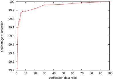
5.1
Dependency W.R.T. the Verification Ratio
We first study the number Nverif of source symbols that must be verified (i.e. the number of symbols in
V ) in order to reach the desired corruption detection probability. It is clear that the higher the Nverif
equal to k since the hash is then computed over the whole object. However we also want to keep the verification processing overhead to a minimum, and from this point of view Nverif should be as small as
possible. A balance must therefore be found.
In order to find an appropriate value, we carried out several experiments: for each verification ratio value (i.e. Nverif/k ratio), 50, 000 runs are performed and we calculate the percentage of corrupted
objects detected. The results are shown in Figure 3.
99.2 99.3 99.4 99.5 99.6 99.7 99.8 99.9 100 0 10 20 30 40 50 60 70 80 90 100 percentage of detection
verification data ratio
Figure 3: Object corruption detection probability as a function of the verification ratio
As expected the detection probability increases with the number of verifications. From Figure 3 we see that checking only 1% of the decoded object enables a detection of 99.22% of the attacks, and we can reach a 99.90% detection probability with a verification ratio of 10% only.
For the rest of the paper, we consider that verifying 5% of the symbols to achieve a corruption detection probability of 99.86% is a good balance between detection and computation overhead.
5.2
Computing Overhead Gains
Since the verification ratio is now set to 5%, we can study the computing overhead gains of our solution with respect to the reference solution (standard FEC codec and signed hash over the entire object, section 1.4). Therefore we have measured the various times for each system, both at a sender and at a receiver, and we have calculated the average values over 200 runs. The hash function used both for the partial hash of VeriFEC and the complete hash of the standard solution is one of MD5 (that no longer provides a sufficient security), RIPEMD-160, SHA-1 and SHA-256. The various times are measured on a Dual-Core Intel Xeon 5120 processor, 1.86 GHz/4 GB RAM/Linux host. The symbol size is set to 1024 bytes, which means that we are dealing with 20 MB objects, adding 10 MB of parity data.
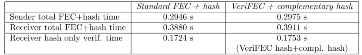
In Table 1, we report the FEC encoding/hash calculation times of both schemes (sender), the FEC decoding/hash verification times of both schemes (receiver), and the verification time only, which repre-sents the hash (partial or total) verification time only at a receiver. Figure 4 focuses on the gains made possible by VeriFEC at a receiver only, for the whole FEC decoding/hash verification process.
We see that the relative gains are very significant, especially with modern, strengthened message digest algorithms, that incur a significant processing load. With SHA-1, if we focus only on the receiver (the main goal of this work), the relative gains for FEC decoding/hash verification made possible by VeriFEC amounts to 31.74%. With SHA-256, this gain is more significant and amounts to 59.24%. If
MD5 RIPEMD160 SHA-1 SHA-256 Sender: total time
Traditional FEC+hash (s) 0.1712 s 0.2681 s 0.1972 s 0.4084 s VeriFEC (s) 0.1092 s 0.1120 s 0.1086 s 0.1208 s Relative gain (4%) 36.2% 58.2% 44.9% 70.4%
Receiver: total time
Traditional FEC+hash (s) 0.2513 s 0.3461 s 0.2795 s 0.4853 s VeriFEC (s) 0.1893 s 0.1901 s 0.1909 s 0.1978 s Relative gain (4%) 24.7% 45.1% 31.7% 59.2%
Receiver: verification time only
Traditional hash verif. (s) 0.0657 s 0.1646 s 0.0937 s 0.3032 s VeriFEC verification (s) 0.0037 s 0.0086 s 0.0051 s 0.0157 s Relative gain (4%) 94.4% 94.8% 94.6% 94.8% Table 1: Processing time of VeriFEC compared to the standard FEC+hash scheme.
0 0.1 0.2 0.3 0.4 0.5 SHA-256 SHA-1 RIPEMD160 MD5 0 0.1 0.2 0.3 0.4 0.5 CPU time (s)
FEC decoding/Hash verification times (Dual Core Intel Xeon [email protected]) FEC+Hash
VeriFEC
Figure 4: VeriFEC ”FEC decoding/hash verification” time at a receiver compared to the standard FEC+hash scheme.
we focus only on the verification process, we observe that VeriFEC reduces the overhead by 94, 64%, which is in line with the theoretical 95% improvement (since we only check 5% of the symbols).
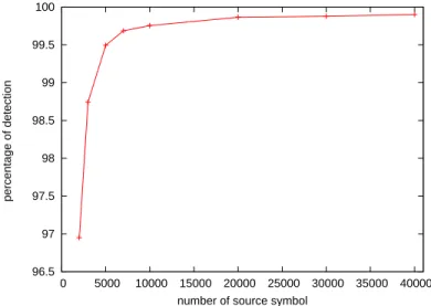
5.3
Dependency W.R.T. the Object Size
We now analyze the influence of the object size (in terms of the number source symbols, regardless of the symbol size which has no influence) on the corruption detection probability. Since this parameter was fixed in the previous experiments, we now want to make sure that the VeriFEC efficiency remains good
for different object sizes. For each size, 50, 000 runs are performed and we plot the measured corruption detection probability. 96.5 97 97.5 98 98.5 99 99.5 100 0 5000 10000 15000 20000 25000 30000 35000 40000 percentage of detection
number of source symbol
Figure 5: Corruption detection percentage as a function of the object size (in number of symbols). Figure 5 shows that the detection probability quickly increases with the number of source symbols in the object. This behavior is easily explained by the fact that when the number of source symbols increases, the number of decoding steps increases too, and so does the number of symbols rebuilt from a given symbol. So the probability that a corrupted symbols will corrupt a large number of symbols increases too. This figure also shows that our system is efficient for objects containing more than 4000 symbols (98.75% detection probability). This behavior is in line with the LDPC-staircase packet erasure correction capabilities, since this large block AL-FEC code is known to perform well when the number of symbols exceeds a few thousands [19]. So the VeriFEC system matches well the operational conditions of the underlying LDPC-staircase codes.
5.4
Dependency W.R.T. the FEC Coding Rate
We now analyze the influence of the FEC coding rate (or its inverse, the FEC expansion ratio) on the corruption detection probability. Since this parameter was fixed in the previous experiments, we now want to make sure that the VeriFEC efficiency remains good for different coding rates. For each coding rate, 50, 000 runs are performed and we plot the measured corruption detection percentage.
Figure 6 shows that the detection probability remains fairly stable (between 99.53% to 99.90%) even when the coding rate largely varies (between 0.33 (FEC Expansion ratio 3.0) and 0.91 (FEC Expansion ratio 1.1)). Note that using coding rates below 0.33 is not recommended with LDPC-staircase codes [19].
6
Additional Attacks and Counter-Measures
We have detailed so far the proposed scheme and have shown its efficiency both in terms of corrup-tion deteccorrup-tion capabilities and computing overhead gains. So far we assumed that the attacker chooses randomly the corrupted symbol. In this section we discuss some possible attacks on our systems and introduce simple yet very efficient counter-measures.
99.5 99.55 99.6 99.65 99.7 99.75 99.8 99.85 99.9 1 1.2 1.4 1.6 1.8 2 2.2 2.4 2.6 2.8 3 percentage of detection Expansion ratio
Figure 6: Corruption detection percentage as a function of the FEC expansion ratio (i.e. 1 coding rate).
6.1
Corruption of a Weak Symbol
Description of the Attack
We call a weak symbol a symbol that enables to rebuild, directly or indirectly, only a small number of source symbols, or, as an extreme case, no symbol. We know that these symbols exist since Figure 1 shows that when only one incoming symbol is corrupted, some tests lead to a very small number of corruptions after decoding (sometimes none), even if the average value is high.
Therefore, if a weak symbol is corrupted, the corruption will not propagate to other symbols, or only in a very limited way. Since the VeriFEC scheme relies on the corruption propagation phenomenon, these weak symbols are potential pitfalls. More precisely, if a weak source symbol is corrupted, and if this corruption does not propagate to other source symbols, the attacker has a 95% probability (since only 5% of the source symbols are checked) for the corruption not to be detected.
To take advantage of this potential weakness, the attacker can spot these weak symbols by performing the same decoding as the receiver, giving the incoming symbols in the same order as the receiver will do. This is made possible by three reasonable assumptions:
the receiver probably uses the reference LDPC-staircase codec [21] and therefore the iterative de-coding algorithm of this codec2
;
the receiver probably submits the incoming symbols to the LDPC-staircase decoder by following the packet arrival order;
the path between the attacker and the receiver does not drop packets;
If these conditions are fulfilled, the decoding paths observed by the attacker will be the same as that of the receiver, and the attacker can easily identify weak symbols and choose to corrupt one of them.
2
Let us remind that if the LDPC-staircase algorithm and its parameters are completely specified in [20] in order to enable interoperable implementations, the decoding algorithm is implementation specific since it does not prevent interoperability. So two different codecs can potentially use two different algorithms. In practice, because a high performance reference codec exists, most receivers will probably use the same decoding algorithm.
Countermeasure
To avert this weakness, a simple solution consists in introducing a buffer at the receiver before the LDPC-staircase decoder (Figure 7). The decoder then picks randomly a symbol in this buffer and gives it to the decoder. So the decoding sequence is hidden from the attacker, and this latter can no longer identify weak symbols. More precisely, the weak symbols that an attacker might identify as explained above are no longer weak symbols at the receiver since the decoding paths have completely changed.
Figure 7: Weak symbol attack counter-measure with a reordering buffer.
In practice, adding such a buffer is not an issue since most FLUTE/ALC reliable file delivery applica-tions that will take advantage of VeriFEC already implement them (see [16] for an example of open-source FLUTE/ALC implementation). So this counter-measure does not add any significant memory overhead to the whole system.
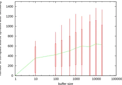
In order to asses the efficiency of this countermeasure and to find an appropriate reordering buffer size, we carried out several experiments. In these experiments the various parameters (i.e. the seeds used in LDPC-staircase and in VeriFEC) are fixed. The corrupted symbol (also fixed) is a weak symbol when the receiver does not use reordering. Then we introduce a buffer at the receiver before the LDPC-staircase decoder and we count the number of corrupted symbols after decoding. For a given window size, we perform 20, 000 tests, each of them with a different reordering.
0 200 400 600 800 1000 1200 1400 1 10 100 1000 10000 100000
number of corrupted source symbols after decoding
buffer size
Figure 8: Efficiency of the weak symbol attack counter-measure as a function of the buffer size. Figure 8 illustrates this counter-measure efficiency. We see that even a very small buffer size (10 symbols) allows to avert the attack (visible when the buffer size equals to 1). Using a buffer of 100 symbols (i.e. 0.5% of the object size) is sufficient in practice to prevent the attack.
Note that these experiments also justify the choice of a random packet transmission order made in the experiments of sections 3.2.2 and 5. Decoding will in any case follow a random scheme at the receiver, no matter the way symbols are transmitted.
6.2
Modification of the Packet Stream
Description of the Attack
Another potential attack consists in intercepting all symbols and forwarding to the receiver only symbols chosen so that the attacker controls the corruption propagation phenomenon.
For instance the attacker can choose to drop all the parity symbols. Without parity symbols, no decoding will take place at the receiver, and without decoding, a corruption on a source symbol will not spread to other symbols. The attacker has therefore a 95% probability (since only 5% of the source symbols are checked) for the corruption not to be detected if the subset V is hidden. If V is known to the attacker, then the attack will succeed all the time.
However some source packets might be erased from the path between the attacker and the receiver (no parity symbol is transmitted any more). This is a problem for the attacker since it can prevent the receiver to rebuild the object, which compromises the attack. A solution to achieve reliable transmissions consists in repeating each source symbol. The transmission efficiency will be rather poor, but this is not the primary concern of an attacker.
Countermeasure
The counter-measure is based on the following idea: in this attack, the incoming symbol stream seen by the receiver is largely different from the one produced by the sender. If the receiver knows the sender’s data flow properties, by checking that the incoming data flow fulfills these properties, he can get a good assurance that the data stream has not been significantly altered by a potential attacker.
Since some packets can get erased or re-ordered during the transmission, even if there’s no attacker, the incoming packet stream seen by the receiver differs from the outgoing packet stream sent by the sender. So the stream verifier must be intelligent enough to accommodate these normal differences between the theoretical and actual packet streams.
For instance, if the sender uses a random transmission order (which has in any case many advantages in case of a FLUTE/ALC application [18]), then no matter the loss model, the ratio between the source and parity symbols of the incoming stream should not significantly differ from that of the outgoing stream. Another possibility consists in checking the incoming packet sequence numbers and making sure that they do not differ significantly from that of the outgoing stream. Indeed the sender can communicate to the receiver the algorithm used to define the outgoing stream (and possibly the PRNG seed in case of a random transmission order). The receiver can then reconstruct locally the theoretical incoming packet sequence and check with the actual stream, taking into account that erasures and reordering might occur.
7
Making VeriFEC 100% Safe
As explained before, the VeriFEC scheme has a non-null probability of false negative (0.14% probability). This service might be sufficient. If this is not the case, we can easily reach a 100% corruption detection probability by using one of the following methods3
. 3
In fact this ultimate 100 % corruption detection capability is only limited by the hash algorithm itself. From that point of view, the use of modern cryptographic message digest algorithms like SHA-256 or RIPEMD-160 is recommended.
7.1
Adding a Hash over the Whole Object
A first idea is to use VeriFEC as a preliminary check and then to use a full check of the object. The vast majority of the corrupted objects (99.86%) will be discarded by the VeriFEC pre-check, with a very limited computation overhead. However if the object is not corrupted, then VeriFEC will add some overhead (6.2% of the time for a complete hash verification) since a hash on the whole object will in any case be calculated.
So VeriFEC as a preliminary verification saves resources when the object is corrupted, but consumes more resources when the object is not corrupted. VeriFEC as a preliminary check will not be profitable if the attacks are rare.
7.2
The Solution: Adding a Complementary Check to VeriFEC
Another idea, that saves some processing time, is the following: since VeriFEC already checks a part of the decoded object, the receiver can compute a complementary hash over the rest of the object (Figure 9). Thanks to this complementary hash, the object integrity can be certified since at the end of the process, all bytes will have been verified.
Figure 9: Integrity verification with a partial and a complementary hash
We can expect a little computation overhead (compared to a hash over the whole object) because the data chunks given to the message digest function during the complementary verification are not necessarily contiguous. However table 2 shows that this overhead is very small.
Standard FEC + hash VeriFEC + complementary hash Sender total FEC+hash time 0.2946 s 0.2975 s
Receiver total FEC+hash time 0.3880 s 0.3911 s Receiver hash only verif. time 0.1724 s 0.1753 s
(VeriFEC hash+compl. hash) Table 2: Processing time of the ”VeriFEC plus complementary verification” compared to a complete verification.
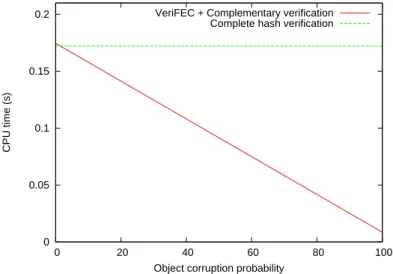
In order to better appreciate the benefits of this approach, we can analyze the verification time as a function of the object corruption ratio (i.e. the ratio of objects corrupted by an attacker). This verification time is fixed in case of a ”standard FEC plus complete hash” solution. On the opposite, this verification time varies a lot in case of our ”VeriFEC plus complementary hash” system, depending on the object corruption ratio: if very few objects are corrupted, the costly complementary check is almost always performed. On the opposite, if a large number of objects are corrupted, then most corruptions are identified by the (cheap) VeriFEC system, thereby saving processing time.
In order to detail this behavior, let us introduce some notations: TV erif: the average CPU time spent to verify the whole object,
TP artial Hash: the CPU time for the partial hash verification,
TCompl Hash: the CPU time for the complementary hash verification,
PObject Corruption: the transmitted object corruption ratio,
PP artial Hash Detection: the probability for the partial hash to detect the corruption.
With the ”VeriFEC plus complementary hash” system, the average verification time as a function of the object corruption ratio is given by:
TV erif = TP artial Hash+ TCompl Hash(1 − PObject Corruption× PP artial Hash Detection)
We use PP artial Hash Detection = 0.9986 (section 5.1). We have experimentally measured the other
parameters and found that on average: TP artial Hash= 0.0091s and TCompl Hash= 0.1662s.
0 0.05 0.1 0.15 0.2 0 20 40 60 80 100 CPU time (s)
Object corruption probability VeriFEC + Complementary verification
Complete hash verification
Figure 10: Verification time as a function of the object corruption probability.
Figure 10 shows the two curves, for each solution, not including the FEC decoding time (identical in both cases). We see that if there is no corruption, our system adds a little overhead. This overhead becomes null when the corrupted object ratio is 1.3%. As the corrupted object ratio increases, our system becomes more and more interesting.
7.3
Application
The ”VeriFEC plus complementary hash” system is a good counter measure against DoS attacks (sec-tion 3.1), where the attacker tries to consume as much receiver resources as possible. Indeed, in case of DoS attacks the attacker will corrupt as many objects as possible. With our solution, the time consumed to check the data integrity will be reduced compared to the traditional solution where a hash over all the objects is needed. The trade-off is that when there is no attack, a little overhead is added.
If this overhead is not acceptable, a receiver can use a ”standard FEC plus complete hash” scheme by default, and switch to a ”VeriFEC plus complementary hash” scheme when too many objects are corrupted.
8
Related works
In [9], the authors present LDPC codes capable of correcting errors and verifying data at the same time. The first approach introduced in this paper provides a scheme that corrects errors and verifies symbols with a ”very high” probability when the errors are random. However an intelligent attacker will never randomly corrupt the data if it corresponds to a weakness of the approach, so the authors suggest to use code scrambling. With code scrambling, the sender and the receiver use a secret permutation over GF(q) that is applied to the data. If this permutation is hidden to the attacker, any attack on the scrambled data will be equivalent to a random attack on the original data. This permutation solves the weakness, however: (1) the computation time will be increased significantly, and (2) a secret must be shared by the sender and each receiver, which is a difficult issue in practice. This work has several additional limitations: (1) no performance results are presented; and (2) if it is clear that the probability that a corrupted symbol remains decreases when the number of decoding rounds increases, the authors do not estimate the average number of rounds needed to reach a target corruption free probability.
Therefore we can conclude that this work significantly differs from ours: (1) we clearly want to keep the computing overhead to a minimum, which prevents the use of data scrambling as suggested by the authors, and (2) we do not require to share any secret between the sender and the receiver(s), a digital signature over the {verif seed; partial hash} tuple, using asymmetric cryptography, is sufficient if no secure channel exists.
In [4], the authors introduce the idea of detecting a corruption by computing the hash of only a part of the object. The technique is called Striped Hashing. The final goal of this work is to provide a system capable of checking the code of a running process without slowing the system down. The subset of bytes included in the stripped hash follow a specific pattern. This pattern aims at maximizing the detection probability of a corruption of several contiguous bytes in the data. The striped hash technique efficiency is significantly lower than our technique. Indeed, considering the corruption of a single byte, our system can detect the attack with a high probability (99.86%). This is made possible because VeriFEC takes advantage of the corruption propagation phenomenon introduced by the FEC decoding. On the opposite, the detection probability of the striped hash is proportional to percentage of data taken by the stripe hash. Reaching the same detection probability as in VeriFEC requires to perform a hash over most of the object.
In [7] the authors present a system that allows to verify on the fly the symbols before decoding. This verification is done thanks to a homomorphic collision-resistant hash function. An advantage of this solution is that only correct symbols are used by the decoder. So the decoded object is guaranteed not to be corrupted if decoding succeeds. But this solution requires the use of addition over Zq which are much
more expensive than the Exclusive-OR operations used by our LDPC-staircase FEC codec. According to the authors, the system adds around 500% processing time overhead. This totally contradicts our goals of keeping the overhead as low as possible. Additionally, there is also a significant transmission overhead since a hash must be transmitted for each source symbol, whereas VeriFEC only requires the transmission of a single tuple, {verif seed; partial hash}.
9
Conclusions
In this work we have shown that corruption detection capabilities can be efficiently added to the LDPC-staircase large block AL-FEC codes. We have designed, implemented, and carried out many experiments in order to asses the detection and computation performances of the proposed scheme. We found that the VeriFEC scheme can detect 99.86% of the most difficult attacks (i.e. where a single byte within the object is corrupted) for less than 6% of the computation overhead required for a complete hash of the object. If the attack is less subtle (e.g. by corrupting several symbols), then the detection capabilities will significantly increase, reaching almost 100% probability.
However the VeriFEC scheme has a non null (but small, around 0.14%) false positive probability (i.e. non detection of a corruption). Therefore VeriFEC cannot be used to certify the integrity of an object.
This service can be sufficient to many applications. If this is not the case, we have shown that a complementary check can be added to provide a 100% detection capability. In that case, our proposal can be considered as a pre-check, capable of quickly removing almost all corrupted objects for only a fraction (6.2%) of the overhead of a traditional hash computation over the whole object. It can therefore be of great help to mitigate DoS attacks.
Since the VeriFEC scheme does not include any mechanism that would limit its scalability (e.g. there is no data flow sent to the sender nor any requirement for encryption), it is well suited to massively scalable broadcasting systems over lossy channels.
Future works will analyze the corruption propagation phenomenon with other LDPC codes and other decoding algorithms, for instance when decoding relies totally or partially on a Gaussian elimination approach.
References
[1] 3rd Generation Partnership Project; Technical Specification Group Services and System Aspects; Multimedia Broadcast/Multicast Setvice; Protocols and Codecs (Release 6), November 2004. 3GPP TS 26.346 v1.5.0.
[2] IP Datacast Over DVB-H: Content Delivery Protocols; TM 3350 Rev.1, September 2005. ETSI, DVB, CBMS Working Group.
[3] Mihir Bellare, Ran Canetti, and Hugo Krawczyk. Keying hash functions for message authentication. Lecture Notes in Computer Science, 1109, 1996.
[4] George I. David and Jeremy A. Hansen. A preliminary exploration of striped hashing a probabilistic scheme to speed up existing hash algorithms. Second International Conference on e-Business and Telecommunication Networks, October 2005.
[5] H. Dobbertin, A. Bosselaers, and B. Preneel. RIPEMD-160: A strengthened version of RIPEMD. 1996.
[6] R. G. Gallager. Low density parity check codes. IEEE Transactions on Information Theory, 8(1), January 1962.
[7] M. Krohn, M. Freedman, and D. eres. In-the-fly verification of rateless erasure codes for efficient content distribution. In IEEE Symposium on Security and Privacy, May 2004.
[8] M. Luby, J. Gemmell, L. Vicisano, L. Rizzo, and J. Crowcroft. Asynchronous Layered Coding (ALC) protocol instantiation, December 2002. IETF Request for Comments, RFC3450.
[9] M. Luby and M. Mitzenmacher. Verification based decoding for packet based low-density parity check codes. January 2005.
[10] M. Luby, A. Shokrollahi, M. Watson, and T. Stockhammer. Raptor Forward Error Correction Scheme for Object Delivery, January 2007. IETF RMT Working Group, Work in Progress: <draft-ietf-rmt-bb-fec-raptor-object-05.txt>.
[11] D. MacKay. Information Theory, Inference and Learning Algorithms. Cambridge University Press, ISBN: 0521642981, 2003.
[12] C. Neumann, V. Roca, A. Francillon, and D. Furodet. Impacts of packet scheduling and packet loss distribution on fec performances: Observations and recommendations. In ACM CoNEXT’05 Conference, Toulouse, France, October 2005.
[13] T. Paila, M. Luby, R. Lehtonen, V. Roca, and R. Walsh. FLUTE - File Delivery over Unidirectional Transport, October 2004. IETF RMT Working Group, Request For Comments, RFC 3926.
[14] R. L. Rivest, A. Shamir, and L. M. Adelman. A method for obtaining digital signatures and public-key cryptosystems. Technical Report MIT/LCS/TM-82, 1977.
[15] L. Rizzo. Effective erasure codes for reliable computer communication protocols. ACM Computer Communication Review, 27(2), April 1997.
[16] V. Roca and al. Plan`ete-BCAST: Tools for large scale content distribution. URL: http://planete-bcast.inrialpes.fr/.
[17] V. Roca, A. Francillon, and S. Faurite. TESLA source authentication in the ALC and NORM protocols, June 2006. IETF RMT Working Group, Work in Progress: <draft-msec-tesla-for-alc-norm-00.txt>.
[18] V. Roca and B. Mordelet. Design of a multicast file transfer tool on top of alc. In 7th IEEE Symposium on Computers and Communications (ISCC’02), Toarmina, Italy, July 2002.
[19] V. Roca and C. Neumann. Design, evaluation and comparison of four large block fec codecs, ldpc, ldgm, ldgm staircase and ldgm triangle, plus a reed-solomon small block fec codec. Research Report 5225, INRIA, June 2004.
[20] V. Roca, C. Neumann, and D. Furodet. Low Density Parity Check (LDPC) Forward Error Correc-tion, December 2006. Work in Progress: <draft-ietf-rmt-fec-bb-ldpc-04.txt>.
[21] V. Roca, C. Neumann, and J. Labour´e. An Open-Source LDPC Large Block FEC Codec. URL: http://planete-bcast.inrialpes.fr/.
[22] U.S. National Institute of Standards and Technology (NIST). The Keyed-Hash Message Authenti-cation Code (HMAC). Federal Information Processing Standards PubliAuthenti-cation 198 (FIPS PUB 198), March 2002.
Unité de recherche INRIA Futurs : Parc Club Orsay Université - ZAC des Vignes 4, rue Jacques Monod - 91893 ORSAY Cedex (France)
Unité de recherche INRIA Lorraine : LORIA, Technopôle de Nancy-Brabois - Campus scientifique 615, rue du Jardin Botanique - BP 101 - 54602 Villers-lès-Nancy Cedex (France)
Unité de recherche INRIA Rennes : IRISA, Campus universitaire de Beaulieu - 35042 Rennes Cedex (France) Unité de recherche INRIA Rocquencourt : Domaine de Voluceau - Rocquencourt - BP 105 - 78153 Le Chesnay Cedex (France)
Unité de recherche INRIA Sophia Antipolis : 2004, route des Lucioles - BP 93 - 06902 Sophia Antipolis Cedex (France)
Éditeur