HAL Id: hal-01084509
https://hal.archives-ouvertes.fr/hal-01084509
Submitted on 19 Nov 2014HAL is a multi-disciplinary open access archive for the deposit and dissemination of sci-entific research documents, whether they are pub-lished or not. The documents may come from teaching and research institutions in France or abroad, or from public or private research centers.
L’archive ouverte pluridisciplinaire HAL, est destinée au dépôt et à la diffusion de documents scientifiques de niveau recherche, publiés ou non, émanant des établissements d’enseignement et de recherche français ou étrangers, des laboratoires publics ou privés.
General Synthesis Report of the Different ADS Design
Status. Establishment of a Catalogue of the R&D needs
G. Rimpault, Patrick Richard, L. Mansani, F. Frogheri, A. Woaye-Hune, S.
Ehster-Vignoud, S. Larmignat, A. Mueller, J.L. Biarotte, C. Artioli, et al.
To cite this version:
G. Rimpault, Patrick Richard, L. Mansani, F. Frogheri, A. Woaye-Hune, et al.. General Synthesis Re-port of the Different ADS Design Status. Establishment of a Catalogue of the R&D needs. [Contract] EURATOM. 2010. �hal-01084509�
DEN/CAD/DER/SPRC RT 2010 SPRC/LEDC/10-2
Indice 0
Document Technique DEN
Page 1 / 230
This document refers to work being performed by scientists and institutions involved in IP EUROTRANS, as
Direction de l’Énergie Nucléaire Direction du Centre de Cadarache Département d’Études des Réacteurs Service de Physique des Réacteurs et du Cycle Laboratoire d’Etudes et Développements des Cœurs
10PPMU000003 DO 2 14/01/10
CEA/DEN/CAD/DER/SPRC/LEDC
diffusé le : 14/01/10
Rapport Technique DEN
General Synthesis Report of the Different ADS Design Status.
Establishment of a Catalogue of the R&D needs.
Référence
SPRC/LEDC/RT 10-2Commissariat à l’Énergie Atomique Centre : CADARACHE
Adresse de l’unité émettrice : DER/SPRC Bâtiment 230A 13108 SAINT PAUL LEZ DURANCE CEDEX - FRANCE
Tél. : 04.42.25.26.05 Fax : 04.42.25.75.95 Courriel : sprcledccad@cea.fr
Établissement Public à caractère Industriel et Commercial RCS Paris B 775 685 019
Authors
G. Rimpault, P. Richard (CEA), L. Mansani, F. Frogheri (ANSALDO), A. Woaye-Hune, S. Ehster-Vignoud, S. Larmignat (AREVA), A. Mueller, J.-L. Biarrotte (CNRS), C. Artioli, G. Glinatsis (ENEA), M. Schikorr, D. Struwe, W. Maschek (FZK), D. De Bruyn, D. Maes, G. Van den Eynde,V. Sobolev(SCK•CEN), J. Wallenius (KTH), A. Guertin (Subatech), Carmen Angulo
(Tractebel Engineering) with contributions from
DEN/CAD/DER/SPRC RT 2010 SPRC/LEDC/10-2
Indice 0
Document Technique DEN
Page 3 / 230
KEY WORDS MOTS CLEFS
Transmutation, EUROTRANS, ADS Design
RÉSUMÉ /CONCLUSIONS
This document is a General Synthesis Report of the Different ADS Design Status being designed within the EUROTRANS Integrated Project; an FP6 European commission partially funded programme. This project had the goal to demonstrate the possibility of nuclear waste transmutation/burning in Accelerator Driven Systems (ADS) at industrial scale.
The focus is on a Pb-cooled ADS for the European Facility on Industrial scale Transmuter (ETD/EFIT) with a back-up solution based on an He cooled ADS.
As an intermediate step towards this industrial-scale prototype, an eXperimental Transmuter based on ADS concept (ETD/XT-ADS) able to demonstrate both the feasibility of the ADS concept and to accumulate experience when using dedicated fuel sub-assemblies or dedicated pins within a MOX fuel core has been also studied.
The two machines (XT-ADS and Pb cooled EFIT) have been designed in a consistent way bringing more credibility to the potential licensing of these plants and with sufficient details to allow definition of the critical issues as regards design, safety and associated technological and basic R&D needs. The different designs fit rather well with the technical objectives fixed at the beginning of the project in consistency with the European Roadmap on ADS development.
For what concerns the accelerator, the superconducting LINAC has been clearly assessed as the most suitable concept for the three reactors in particular with respect to the stringent requirements on reliability. Associated R&D needs have been identified and will be focused on critical components (injector, cryomodule) long term testing.
The design of the different ADS has been performed in view of what is reasonably achievable pending the completion of R&D programmes. The way the EUROTRANS Integrated Project has been organised with other domains than the DM1 Design being specifically devoted to R&D tasks in support to the overall ETD/EFIT and ETD/XT-ADS design tasks has been helpful. The other domains were centred on the assessment of reactivity measurement techniques (DM2 ECATS), on the development of U-free dedicated fuels (DM3 AFTRA), on materials behaviour and heavy liquid metal technology (DM4 DEMETRA) and on nuclear data assessment (DM5 NUDATRA). Pending questions associated to technology gaps have been identified through the different appropriate R&D work programmes and a Catalogue of the R&D needs has been established.
Finally, the work within the EUROTRANS integrated project has provided an overall assessment of the feasibility at a reasonable cost for an ADS based transmutation so that a decision can be taken to launch a detailed design and construction of the intermediate step Experimental ADS now already launched within the 7th FP programme under the name of Common Design Team (CDT).
DEN/CAD/DER/SPRC RT 2010 SPRC/LEDC/10-2
Indice 0
Document Technique DEN
Page 4 / 230
BORDEREAU D’ENVOI
Date : 31/03/2010 N/Réf : CEA/DEN/CAD/DER/SPRC RT SPRC/LEDC 10-2 Indice 0 Destinataires : Nombre Observations SCK.MOL D. DE BRUYN DEN/SAC/DISN/R4G J. ROUAULT DEN/SAC/DISN/R4G P. ANZIEU DEN/DER A. ZAETTA G. WILLERMOZ DEN/DER/SPRC D. GIBIAT DEN/DER/SESI Ph DARDE C. RENAULT DEN/SPEX/LPE J.C. BOSQ F. MELLIER Ch. JAMMES Ch. DESTOUCHES DEN/DER/SESI/L4G F. VARAINE P. RICHARD G. GRANGET DEN/DER/SESI/LE2S D. PLANCQ JF PIGNATEL T. CADIOU DEN/DEC/SESC F. DELAGE P. JACKY S. PILLON 1 1 1 1 1 1 1 1 1 1 1 1 1 1 1 1 1 1 1 1 1Diffusion du document complet
(transmis par courriel sous format PDF) Avec issue certificate
Pour diffusion interne EUROTRANS
DEN/CAD/DER/SPRC RT 2010 SPRC/LEDC/10-2
Indice 0
Document Technique DEN
Page 5 / 230
BORDEREAU D’ENVOI (Suite)
Date : 31/03/2010 N/Réf : CEA/DEN/CAD/DER/SPRC RT SPRC/LEDC 10-2 Indice 0 Destinataires : Nombre Observations DSM/IRFU/ShN S. LERAY DSM/DAPNIA/SACM R. GOBIN DEN/DTN/DIR Ch. LATGE DEN/DTN/STPA/LTRS F. BEAUCHAMP DEN/DENS/DPC/SCCME/LECNA F. BALBAUD DEN/DMN/SRMA/LA2M J. HENRY DEN/DPC/SCCME/LECNA JL. COUROUAU DEN/ITESE F. LEGEE G. MATHONNIERE DEN/SAC/DISN/R4G DEN/CAD/DEC DEN/CAD/DER DEN/CAD/DER/SESI DEN/CAD/DER/SPEX DEN/GRE/DER/SSTH 1 1 1 1 1 1 1 1 1 1 1 1 1 1 1
Diffusion du document complet
(transmis par courriel sous format PDF)
DEN/CAD/DER/SPRC RT 2010 SPRC/LEDC/10-2
Indice 0
Document Technique DEN
Page 6 / 230
SUMMARY
1. INTRODUCTION AND SCOPE ... 11
1.1 ADS UNDERLYING OBJECTIVES ... 12
1.2 PERSPECTIVES ON PARTITIONING &TRANSMUTATION ... 12
1.2.1 ORIGIN OF NUCLEAR WASTE ... 12
1.2.2 RADIO-TOXICITY ... 15
1.3 FUEL CHOICES ... 16
2. DESCRIPTION OF THE ETD ACCELERATOR ... 20
2.1 BEAM CHARACTERISTICS ... 20
2.1.1 ACCELERATOR GENERAL PERFORMANCES ... 20
2.1.2 RELIABILITY AND AVAILABILITY ... 20
2.1.3 OPERATION ... 21
2.1.4 ACCELERATOR BEAM TIME STRUCTURE FOR DYNAMIC REACTIVITY MEASUREMENTS ... 22
2.2 THE REFERENCE ADSACCELERATOR ... 22
2.2.1 THE LINAC FRONT-END ... 23
2.2.2 THE INDEPENDENTLY-PHASED SCLINAC ... 24
2.2.3 THE FINAL BEAM TRANSPORT LINE ... 26
2.2.4 RELIABILITY-ORIENTED DESIGN ... 26
2.2.5 TOLERANCE TO RFFAULTS IN THE SCLINAC ... 27
2.2.6 RELIABILITY ANALYSIS AND DISCUSSION ... 28
2.2.7 CONCLUSION ON THE ACCELERATOR DESIGN ... 28
2.3 RATIONALE FOR THE MAXIMUM ALLOWABLE NUMBER OF BEAM TRIPS ... 29
2.3.1 METHODOLOGY ... 29
2.3.2 PHENIX OPERATION AND ALLOWABLE NUMBER OF SCRAM ... 29
2.3.3 OPERATING TRANSIENTS AND DAMAGE THROUGH FATIGUE AND/OR FATIGUE-CREEP ... 30
2.3.4 STRUCTURE INTEGRITY DUE TO BEAM TRIPS... 31
2.3.4.1 Main components ... 31
2.3.4.2 Fuel Elements ... 32
2.3.5 PERSPECTIVES FOR THE MAXIMUM ALLOWABLE BEAM TRIPS ... 34
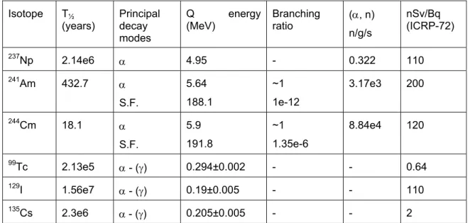
3. DESCRIPTION OF THE 395 MWTH PB-COOLED EFIT ... 37
3.1 CHOICE OF COOLANT TEMPERATURES ... 37
3.2 EFIT-PB CORE DESIGN ... 39
3.2.1 DESIGN APPROACH ... 39
3.2.2 CORE DESCRIPTION ... 41
3.2.3 DECAY HEAT GENERATION. ... 43
3.2.4 SUMMARY OF THE CERCER CORE DESIGN ... 44
3.2.5 THE CERMET CORE DESIGN VARIANT ... 44
3.3 EFIT-PB PRIMARY SYSTEM ... 46
3.3.1 MAIN LAY OUT DESCRIPTION ... 46
DEN/CAD/DER/SPRC RT 2010 SPRC/LEDC/10-2
Indice 0
Document Technique DEN
Page 7 / 230
3.3.2.1 Reactor Vessel and Support System ... 50
3.3.2.2 Internal structure ... 51
3.3.3 STEAM GENERATOR AND PRIMARY PUMP SUB-ASSEMBLY ... 51
3.3.3.1 Steam generator Unit ... 51
3.3.3.2 Primary coolant pumps ... 52
3.4 DECAY HEAT REMOVAL SYSTEM ... 56
3.4.1 DHR1SYSTEM:DIRECTREACTORCOOLING(DRC)SYSTEM ... 56
3.4.2 MOLTEN LEAD-DIATHERMIC OIL HEAT EXCHANGER (DIP COOLER,DHX) ... 56
3.4.3 AIR-DIATHERMIC OIL VAPOUR CONDENSER (AVC) ... 57
3.4.4 ISOLATION CONDENSER SYSTEM ... 58
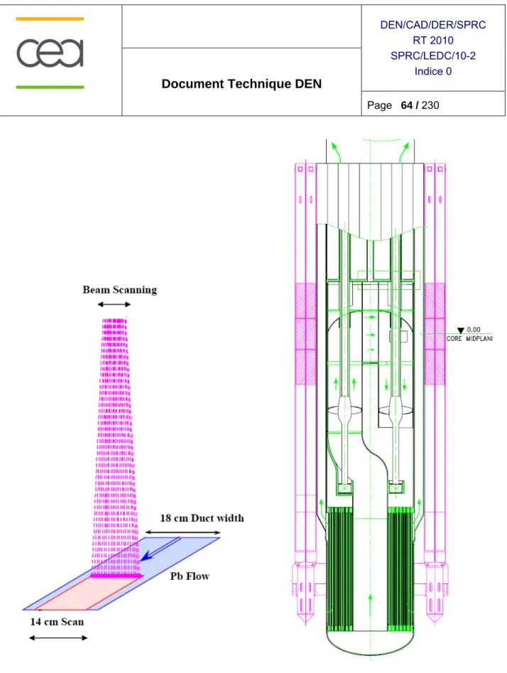
3.5 THE TARGET UNIT... 63
3.6 INTEGRATED COOLANT PURIFICATION UNIT ... 65
3.7 PRIMARY SYSTEM CHEMISTRY CONTROL ... 65
4. DESCRIPTION OF THE 400 MWTH HE-COOLED EFIT ... 68
4.1 DESIGN OBJECTIVES AND CRITERIA CONSIDERED IN THE EFIT-HE DESIGN ... 68
4.2 PLANT CHARACTERISTICS ... 68
4.2.1 DEFINITION OF INLET/OUTLET TEMPERATURES –POWER CONVERSION CYCLE ... 69
4.2.2 FUEL CLADDING ... 70
4.2.3 SUMMARY OF THE MAIN HE EFITPLANT CHARACTERISTICS ... 70
4.3 DESCRIPTION OF THE ACCELERATOR AND SPALLATION TARGET ... 72
4.4 EFIT-HE CORE DESIGN ... 73
4.4.1 MAIN SUB-CRITICAL CORE CHARACTERISTICS ... 73
4.4.2 CORE COMPOSITION ... 74
4.4.3 HE EFIT CORE PERFORMANCES ... 75
4.5 EFIT-HE SYSTEM LAY OUT ... 79
4.6 REACTOR VESSEL AND INTERNALS ... 81
4.6.1 THE DIAGRID ... 81
4.6.2 THE SUPPORT PLATE ... 81
4.6.3 INNER VESSEL ... 82
4.6.4 MAIN VESSEL AND COVER HEAD ... 82
4.7 HEAT EXCHANGER ... 82
4.8 DHR SYSTEM ... 83
5. DESCRIPTION OF THE 57 MWTH LBE-COOLED XT-ADS (MYRRHA) ... 86
5.1 GENERAL DESCRIPTION OF THE XT-ADS PLANT LAY OUT ... 86
5.2 XT-ADS WINDOWLESS SPALLATION TARGET DESIGN ... 88
5.2.1 SPALLATION TARGET BOUNDARY CONDITIONS ... 88
5.2.2 SPALLATION LOOP LAYOUT ... 89
5.2.3 FREE SURFACE AND RECIRCULATION ZONE ... 90
5.2.4 LBE AS COOLANT AND TARGET MATERIAL ... 90
5.2.5 PUMPING OPTIONS ... 90
5.2.6 VACUUM SYSTEM ... 91
5.2.7 DESIGN SUPPORT STUDIES ... 91
DEN/CAD/DER/SPRC RT 2010 SPRC/LEDC/10-2
Indice 0
Document Technique DEN
Page 8 / 230
5.2.9 TARGET NOZZLE ... 92
5.2.10 HEAT DEPOSITION ... 93
5.2.11 THERMAL-HYDRAULICS ... 93
5.2.12 BEAM TARGET INTERACTION ... 94
5.2.13 SAFETY ANALYSIS ... 94
5.3 PRIMARY SYSTEM ... 94
5.3.1 SAFETY CONSTRAINTS ... 94
5.3.2 DESCRIPTION OF THE PRIMARY LOOP ... 96
5.3.3 HEAT EXCHANGERS... 97
5.3.4 PRIMARY PUMPS ... 98
5.3.5 PRIMARY SYSTEM AUXILIARIES ... 98
5.4 SECONDARY SYSTEM ... 99
5.5 DECAY HEAT REMOVAL SYSTEM ... 101
5.6 REACTOR VESSELS, COVER AND DIAPHRAGM ... 101
5.7 CORE SUPPORT STRUCTURE ... 102
5.8 IN-VESSEL FUEL STORAGE ... 102
5.9 IN-VESSEL FUEL HANDLING MACHINES ... 103
5.10 CORE DESIGN ... 104
5.10.1 PRESENTATION OF THE CORE DESIGN ... 104
5.10.2 CRITICALITY AND SOURCE CALCULATIONS ... 107
5.10.3 IRRADIATION CAPABILITIES ... 109
6. SAFETY EVALUATION OF THE ETD CONCEPTS ... 113
6.1 SAFETY STATUS OF EFIT-PB PLANT ... 113
6.1.1 SUBCRITICALITY MARGIN ASSESSMENT ... 113
6.1.2 EFIT-PB SAFETY GUIDELINES ... 113
6.1.3 EFIT-PB ULOF TRANSIENT STUDIES ... 114
6.1.4 OTHER EFIT-PB TRANSIENT STUDIES ... 116
6.1.5 OVERALL EFIT-PB SAFETY STUDIES SUMMARY ... 118
6.2 SAFETY STATUS OF EFIT-HE PLANT ... 121
6.2.1 EFIT-HE SAFETY APPROACH AND PLOF TRANSIENT STUDIES ... 121
6.2.2 OTHER EFIT-HE TRANSIENT STUDIES ... 130
6.2.3 EFIT-HE SAFETY STUDIES SUMMARY ... 132
6.2.4 PLANT BEHAVIOUR UNDER TRANSIENT CONDITIONS ... 132
6.2.5 CORE SAFETY FEATURES ... 133
6.3 SAFETY STATUS OF XT-ADS PLANT ... 134
6.3.1 SAFETY APPROACH FOR THE XT-ADS PLANT ... 134
6.3.2 XT-ADSULOF TRANSIENT STUDIES ... 135
6.3.3 XT-ADS OTHER DBC AND DEC TRANSIENT STUDIES ... 138
6.3.4 XT-ADS OVERALL SAFETY ASSESSMENT STUDIES ... 141
7. CONSISTENCY OF THE DIFFERENT CONCEPTS WITH THE ETD OBJECTIVES ... 144
7.1 EFIT-PB DESIGN ... 144
7.1.1 CURRENT FEATURES ... 144
DEN/CAD/DER/SPRC RT 2010 SPRC/LEDC/10-2
Indice 0
Document Technique DEN
Page 9 / 230 7.2 EFIT-HE DESIGN ... 149 7.3 XT-ADS DESIGN ... 151 8. STRUCTURAL INTEGRITY/ROBUSTNESS ... 155 8.1 EFIT-PB DESIGN ... 155 8.2 EFIT-HE DESIGN ... 158 8.2.1 DHR DESIGN STRATEGY ... 158
8.2.2 EFIT-HE DESIGN ROBUSTNESS ... 160
8.3 XT-ADS DESIGN ... 160
8.3.1 EFIT&XT-ADS COMMON CHARACTERISTICS ... 160
8.3.2 CHANGES COMPARED TO MYRRHADRAFT 2 DESIGN ... 161
8.3.3 DOSE RATES OF THE CORE BARREL AND THE UPPER GRID PLATE AND RECOMMENDATIONS ... 162
8.3.4 XT-ADS CORE SUPPORT STRUCTURES ... 163
8.3.5 FUEL CLADDING ... 165 8.3.6 RECOMMENDATIONS TOWARDS CDT ... 165 9. ECONOMICS ... 167 9.1 XT-ADSCOST ... 167 9.2 EFIT-PB COST ... 168 9.3 ECONOMIC TRENDS ... 169 9.4 RELIABILITY/AVAILABILITY ... 170
10. OPTION VALIDATION STATUS (R&D NEEDS) ... 172
10.1 RELATED R&DACTIVITIES ON THE LINACACCELERATOR ... 172
10.1.1 R&D ACTIVITIES ON THE INJECTOR ... 172
10.1.2 R&D ACTIVITIES ON THE MAIN SUPERCONDUCTING LINAC ... 174
10.1.3 CONCLUSION ON ACCELERATOR R&D NEEDS ... 175
10.2 DM2ECATS(EXPERIMENTAL ACTIVITIES ON THE COUPLING OF AN ACCELERATOR, A SPALLATION TARGET AND A SUB-CRITICAL BLANKET) ... 177
10.2.1 PLANT DESIGN REQUIREMENTS AND EXPERIMENTAL OBJECTIVES ... 177
10.2.2 THE YALINA EXPERIMENTS ... 177
10.2.3 THE RACE EXPERIMENTS ... 180
10.2.4 THEGUINEVEREEXPERIMENTS ... 183
10.2.5 CONCLUSION ON ADS MONITORING AND ACCELERATOR-CORE COUPLING ... 185
10.3 DM3AFTRA(ADVANCED FUELS FOR TRANSMUTATION SYSTEMS ) ... 189
10.3.1 TRU FUEL PERFORMANCE ASSESSMENT AT NORMAL OPERATION CONDITIONS. ... 189
10.3.2 FUEL SAFETY ASSESSMENT ... 189
10.3.3 IRRADIATION TESTS ... 190
10.3.4 OUT-OF-PILE MEASUREMENTS ... 190
10.3.5 CONCLUSION ON U-FREE FUEL ... 191
10.4 DM4DEMETRA(DEVELOPMENT AND ASSESSMENT OF STRUCTURAL MATERIALS AND HEAVY LIQUID METAL TECHNOLOGIES FOR TRANSMUTATION SYSTEMS) ... 193
DEN/CAD/DER/SPRC RT 2010 SPRC/LEDC/10-2
Indice 0
Document Technique DEN
Page 10 / 230
10.4.2 MATERIALS CHARACTERISATION ... 193
10.4.3 IRRADIATION STUDIES ... 196
10.4.4 HLMQUALITY CONTROL ... 197
10.4.5 THERMAL-HYDRAULICS ... 197
10.4.6 CONCLUSION ON PB AND LBE RELATED TECHNOLOGY ... 200
10.5 DM5NUDATRA(NUCLEAR DATA FOR TRANSMUTATION) ... 203
10.5.1 OBJECTIVES OF DM5NUDATRA ... 203
10.5.2 UNCERTAINTY PROPAGATION AND DATA NEEDS OF ETD ADVANCED FUEL CYCLES ... 203
10.5.3 MEASUREMENTS AND EVALUATIONS OF CROSS SECTIONS ... 204
10.5.4 HIGH ENERGY EXPERIMENTS AND MODELLING ... 206
10.5.5 DECAY HEAT IN MA LOADED CORES ... 209
10.5.6 CONCLUSION ON DM5NUDATRA ... 210
10.6 R&DNEEDS SYNTHESIS ... 212
10.6.1 PB-COOLED SYSTEMS ... 212
10.6.1.1 Structural materials ... 212
10.6.1.2 Thermal-hydraulics ... 212
10.6.1.3 Reactor Components ... 213
10.6.1.4 Instrumentation and coolant chemistry control ... 214
10.6.2 GAS-COOLED SYSTEMS ... 215
10.6.2.1 Main Components : RPV and primary circuit ... 215
10.6.2.2 Neutronics ... 216
10.6.2.3 Core Thermal-hydraulics ... 216
10.6.2.4 Tools for compressor/circulator modelling and studies: a multi-scale approach ... 217
10.6.2.5 Helium instrumentation: ... 217
10.6.3 LBE-COOLED SYSTEMS ... 218
11. GENERAL CONCLUSIONS... 220
11.1 MOTIVATION OF THE OVERALL IPEUROTRANS PROJECT ... 220
11.2 DESIGN:EFIT-PB ... 220 11.3 DESIGN:EFIT-HE ... 223 11.4 DESIGN:XT-ADS ... 224 11.5 ACCELERATOR ... 226 11.6 SPALLATION TARGET ... 227 11.7 SAFETY ANALYSIS ... 227 11.8 COST ANALYSIS ... 228 11.9 PERSPECTIVES ... 229 12. ACKNOWLEDGEMENTS... 230
DEN/CAD/DER/SPRC RT 2010 SPRC/LEDC/10-2
Indice 0
Document Technique DEN
Page 11 / 230
1. INTRODUCTION AND SCOPE
The development of the ADS (for Accelerator Driven Systems) is motivated by the potential which have these machines to reduce the volume and the radiotoxicity of the nuclear waste and more particularly of minor actinides generated by the operation of existing pressurized water reactors. This reduction of the volume and the radio-toxicity of such nuclear waste is obtained by transmutation and incineration (i.e. fission) of minor actinides into less active isotopes or shorter-lived by-products.
The overall EUROTRANS integrated project had the goal to demonstrate the possibility of nuclear waste transmutation/burning in Accelerator Driven Systems (ADS) at industrial scale [1.1]. The domain DESIGN, within it, had the task to provide the pre-design of the European Transmutation Demonstrator (ETD) able to achieve such task.
The focus during this FP6 European commission partially funded programme is on a Pb-cooled ADS for the European Facility on Industrial scale Transmuter (ETD/EFIT) with a back-up solution based on an He cooled ADS in continuity with the PDS-XADS 5th FP project [1.2]. It takes credit from the roadmap on Partitioning & Transmutation of the Technical Working Group [1.3] and the FP6 Project PATEROS (P&T European Roadmap for Sustainable Nuclear Energy) [1.4]
As an intermediate step towards this industrial-scale prototype, an eXperimental Transmuter based on ADS concept (ETD/XT-ADS) able to demonstrate both the feasibility of the ADS concept and to accumulate experience when using dedicated fuel sub-assemblies or dedicated pins within a MOX fuel core has been also studied. The possibility of irradiating these dedicated sub-assemblies in conditions which are representative of the ETD/EFIT (after both concepts have been pre-designed) has then be one of the major tasks of these ETD/XT-ADS studies.
The two machines (XT-ADS and EFIT) have been designed in a consistent way bringing more credibility to the potential licensing of these plants. As part of this objective, synergies between both designs have been identified with their respective particular objectives in mind.
The definition of the detailed missions of the different ADS once settled, it has been of primarily importance to design these machines keeping in mind what is reasonably achievable and the conditions under which the design optimization can proceed. The EUROTRANS Integrated Project has been organized in different domains with DM1 Design defining the overall ETD/EFIT and ETD/XT-ADS designs while the others were specifically devoted to R&D tasks. These tasks were centered on the assessment of reactivity measurement techniques (DM2 ECATS), on the development of U-free dedicated fuels (DM3 AFTRA), on materials behavior and heavy liquid metal technology (DM4 DEMETRA) and on nuclear data assessment (DM5 NUDATRA).
The XT-ADS design has been proceeding with margins taking into account the uncertainties associated to the knowledge of the material boundary limits. The ETD/EFIT design has been proceeding with a similar approach but with material boundary limits defined without uncertainties given the expected time of the construction of the plant i.e. in twenty five years. These constraints have been defined at the start of the project [1.2] anticipating some R&D results to come and part of the objective of this document is to review these constraints on the light of the different work progresses of EUROTRANS IP and and the remaining R&D to be performed prior to the construction of the different plants.
This part of the document (Chapter 1) gives a justification to the ADS development for nuclear waste transmutation purposes and their overall general requested characteristics.
It then goes to define the main design aspects of the different plants, the constraints under which the different design works have proceeded in view of their optimizations and, in particular, the material boundary conditions.
DEN/CAD/DER/SPRC RT 2010 SPRC/LEDC/10-2
Indice 0
Document Technique DEN
Page 12 / 230
Chapters 3 to 9 are bound to evaluate the different ETD/EFIT designs in view of their respective objectives. This part includes the possible improvements or refinements, the optimization could proceed in view of possible strategic choices among conflicting constraints.
Chapter 10 makes a status of the R&D i.e. review the different constraints which have been used for designing the different plants and list the R&D still required to achieve the licensing of the plant.
Chapter 11 concludes this document including the degree of feasibility of the plants and their costs.
1.1 ADS underlying objectives
The spent fuel discharged from nuclear power plants constitutes the main contribution to nuclear waste. At present, approximately 2500 tons of spent fuels are produced annually in the EU, containing about 25 tons of plutonium and 3.5 tons of the "minor actinides" neptunium, americium, and curium and 3 tons of long-lived fission products.
These radioactive by-products, although present at relatively low concentrations in the spent fuel, are a hazard to life forms when released into the environment. A measure of the hazard of these elements is provided by the toxicity and in particular the radiotoxicity arising from their radioactive nature rather than their chemical form. The radiotoxicity of the fission products dominates the total radiotoxicity during the first 100 years. Thereafter, their radiotoxicity decreases and reaches the reference level after about 300 years. The long-term radiotoxicity is dominated by the actinides, mainly by the plutonium and americium isotopes. The reference radiotoxicity level is reached by spent nuclear fuel only after periods of more than 100,000 years.
This is the basis of the motivation for partitioning and transmutation programmes worldwide, and for the development of dedicated burner reactors such as Accelerator Driven Systems (ADS) as one possible strategy for the reduction of the volume and radio-toxicity of such wastes. In particular, the major actinide plutonium and the Minor Actinides (MAs) such as neptunium, americium and curium together with some of the more radio-active and volatile/hydrogenous long-lived fission products (LLFPs) such as 135cesium, 129iodine and 99technicium pose the greatest hazards from the point of view of radio-toxicity and proliferation risk. One possible solution offered is transmutation and/or incineration (i.e. fissioning) of the waste into less active isotopes or short-lived by-products in a nuclear reactor [1.5].
1.2 Perspectives on Partitioning &Transmutation
ADS can play a very important role in the P&T perspective and allows a very high level of radio-toxicity reduction.
It has been demonstrated, that same radio-toxicity reduction could be reached by a strategy implementing an electro-nuclear system of advanced fast reactors (AFR), which would provide the same level of radio-toxicity reduction performance as a double strata system. The competitiveness and full feasibility is still under investigations and furthermore, the consequence it has on the economic of the whole fuel cycle is of major concern. Because of this and as the build-up of a fast reactor park has encountered some delays; the major alternative route using ADS appears attractive enough to be further developed. At the R&D level, the ADS development offers many common characteristics with critical systems with fast spectrum and the decision on one or the other route will at the end become a public/political decision.
Therefore it is important to proceed with the R&D and a stepwise demonstration of the technology and of the ADS system, for an industrial prototype implementation around 2035 and a full industrial large scale deployment starting around 2045.
1.2.1 Origin of Nuclear Waste
Most of the reactors operative in the world today are thermal spectrum reactors such as LWRs (Pressurised Water Reactors) or Russian VVERs, BWRs (Boiling Water Reactors), AGRs (Advanced CO2 Gas
DEN/CAD/DER/SPRC RT 2010 SPRC/LEDC/10-2
Indice 0
Document Technique DEN
Page 13 / 230
Reactors), and CANDU D2O types. Some fast spectrum reactors of the sodium or lead-bismuth eutectic cooled type are also in operation but constitute less than one percent of the total worldwide operating fleet. The currently dominant ‘open’ fuel cycle in which uranium fuel is irradiated and then discharged for re-processing (i.e. separation and subsequent storage) before direct replacement with new uranium fuel has resulted in the gradual accumulation of large quantities of highly radioactive or fertile materials in the form of depleted uranium, plutonium, MAs and LLFPs.
Some of the separated products from reprocessed fuels have already been utilised in the past in the form of MOX (Mixed Pu/U Oxide) fuels, but as yet, not in sufficient quantities to significantly slow down the steady accumulation of these materials in storage.
Table 1.1 below shows a typical PWR discharge inventory [1.6] of the long-lived waste products.
Table 1.1: Part of discharge inventory from 900 MWe Uranium (3.7% 235U) fuelled PWR after a burnup of around 40 GWd/t and a cooling period of 5 years. All units are kg/TWhe.
Higher
actinides MAs LLFPs
U 3000 Np 1.8 99Tc 2.9
Pu 33 Am 1.7 129I 0.7
- Cm 0.16 135Cs 1.7
There are other elements produced in-reactor via fissions or capture processes etc, but these are mainly either short-lived (and therefore pose no long term problem following a cooling period during which they may transmute to stable or less active isotopes) or stable. 99Tc, 129I and 135Cs represent the largest contribution to the radiotoxicity of all LLFPs produced in a typical uranium fuelled reactor [1.7].
The total mass of fuel in the reactor quoted in table 1.1 would typically be around 72 tons (~157 assemblies x 0.46 t/ass’). This would give annual discharge totals for the non-uranic elements in table 1.1 of around 200kg of plutonium, 11kg of neptunium, 10kg of americium and 1kg of curium. Additionally, the amounts of LLFPs of interest resulting from fissioning of heavier elements would be around 17kg of 99Tc, 4kg of 129I and 10kg of 135Cs and around another 20 –30 kg of other fission products [1.6].
The situation envisioned for the medium term future is a situation in which spent fuel have been accumulated the operation of PWR plants over a period of 50 years.
This current situation most common in Europe uses PWRs to burn UOX fuels which are then reprocessed to produce MOX fuel. About nine UOX PWR assemblies are required to fabricate a MOX PWR sub-assembly. This situation is mainly driven by the fact that this enable to reduce significantly the number of sub assemblies to store in repositories. The reprocessing of MOX PWR sub assemblies is envisaged at the moment only for regulatory rules. Storing spent fuel at La Hague is allowed only if the spent fuel is going to be reprocessed. Also to be considered is the fact that with the current situation, plutonium inventory is steadily increasing although at a relative limited pace since PWR using MOX fuel are effectively burning Plutonium. Reprocessing of MOX PWR fuel is however envisaged for the deployment of advanced Generation IV reactors. In this scenario, Plutonium will be going in these advanced Generation IV system but not possibly minor actinides since these would pollute the entire fuel cycle. A dedicated fuel cycle would be a less serious burden and hence minor actinides coming from MOX spent fuel could then be introduced in dedicated ADS. It should be mentioned that at the moment nuclear waste from UOX spent fuel are put into glass. These glasses include also minor actinides but although their final disposal is not finally decided, experts do not envisage seriously retrieving these minor actinides from glasses where they make no harm.
DEN/CAD/DER/SPRC RT 2010 SPRC/LEDC/10-2
Indice 0
Document Technique DEN
Page 14 / 230
These ADS will likely be deployed in 30 years which means that the reprocessing will take place only at a time where most of the Pu-241 will have decayed on the Am-241. The scenario briefly described is presented in the following figure 1.1.
Figure 1.1: Reference Scenario of the burning of minor actinides in ADS
This scenario has been applied to the whole Nuclear Reactor Park in Europe by the PATEROS European Project [1.4]. In this scenario, the advanced PUREX reprocessing is required for the PWR spent fuel, to enable to separate not only Uranium from Plutonium and Plutonium from minor actinides and fission products but also minor actinides from fission products. Some breakthroughs in this field are appearing and it is therefore a limited uncertainty for this scenario. The capability to apply advanced reprocessing on sizable amount of spent fuel from commercial power plants (i.e. LWR) in order to separate Pu and MA has been studied within the FP6 project EUROPART (EUROpean research programme for the PARTitioning of minor actinides from high active wastes issuing the reprocessing of spent nuclear fuels) [1.12] and is now being studied by the FP7 project ACSEPT (Actinide reCycling by SEParation and Transmutation) [1.15]. Therefore, minor actinides will then come from the reprocessing of MOX spent fuel. Minor Actinides are hence coming from a MOX spent fuel reprocessing 30 years after it has been irradiated (likely to be the case since both EFIT and GEN-IV reactors are not ready to operate before). Plutonium used in ADS for the first loading (and eventually for some other cycles if the ADS is not correctly optimised) will be coming also from the MOX spent fuel.
MOX spent fuel have been burnt 45 GWd/t since it the current situation in France (at La Hague reprocessing plant, they have only MOX 40 GWd/t PWR fuel). Note that EPR is designed to host both UOX and MOX fuel S/As which will have a 60 GWd/t out load limit which determines the fuel residence time. In the EFIT pre-design studies presented here, the core optimisation has been performed withPu and MA vectors coming from spent fuel: 90% from UO2 cooled down 30 years and 10% from MOX cooled down 15
years, unloaded at 45 GWd/ton, respectively.
UOX PF+losses MOX Am +Np +Cm Fabrication
ADS fuel
ADS
Reprocessing
Pu + Am + Np + Cm
Wastes PF+losses Plutonium from UOX only
S
T O R A G E.S
T O R A G E. WastesPUREX
Reprocessing
Fabrication
UOX
Fabrication
MOX
U enriched
PWR
MOXPWR
UOX Plutonium for Generation IV systemDEN/CAD/DER/SPRC RT 2010 SPRC/LEDC/10-2
Indice 0
Document Technique DEN
Page 15 / 230 1.2.2 Radio-toxicity
In the majority of studies, two main criteria are used to define the degree of significance of the waste produced in-reactor: The total mass (or inventory) of transurania and the subsequent radiotoxicity of that waste. The latter is of direct importance to the human population as a whole and tends to be the primary driving force behind efforts to reduce the growth of existing waste inventories. The radiotoxicity of nuclear waste is defined as the global dose resulting from complete incorporation by the population of the waste product by either ingestion or inhalation and is presently expressed in Sieverts per ton of spent fuel. Note that the Sievert is defined as the amount of ionising radiation required to have the same biological effect as one rad (1 rad=0.01joules/Kg) of high penetration X-rays (equivalent to a ‘Gray’ for X-rays). A recommended choice of unit is, Sv/TWhe as this unit is a measure of the efficiency (or lack of efficiency) of a core for waste burning (or production). For the typical PWR mentioned above, the plutonium accounts for between 70 and 90% of the total radiotoxicity of the discharge products [1.6] for up to 105 years after storage. Consequently, when defining a complete strategy for the treatment of radioactive waste (i.e. close the fuel cycle), it is of prime importance to consider, simultaneously with the MAs and LLFPs, a programme of recycling plutonium.
The one characteristic that all of the MAs and LLFPs under discussion have in common is their high radiotoxicity inventory. For the MAs, after plutonium, the most toxic is Americium followed by Curium. Neptunium is not particularly radiotoxic in its most common isotope (237Np) but can decay to fissile uranium or produce via neutron capture under irradiation the highly active isotope 238Pu (via 237Pu), which is a strong
alpha emitter, in just a few years. Another possibility is the (n, 2n) reaction giving 236Pu (via - decay). The subsequent decay of this isotope and its daughters leads to 208Tl, which is a hard gamma emitter (3.4 MeV). Regarding the radiotoxicity of the LLFPs, it is helpful to compare their activity against that of the main MAs as shown below in Table 1.2.
The Table 1.2 below lists the most prevalent MAs of interest from the uranium fuel cycle together with the most prolific and toxic LLFPs, giving their principle decay modes, energies and dose coefficients.
Table 1.2: General decay data for the main MAs and LLFPs considered Isotope T½
(years) Principal decay modes
Q energy
(MeV) Branching ratio (, n) n/g/s nSv/Bq (ICRP-72) 237Np 2.14e6 4.95 - 0.322 110 241Am 432.7 S.F. 5.64 188.1 ~1 1e-12 3.17e3 200 244Cm 18.1 S.F. 5.9 191.8 ~1 1.35e-6 8.84e4 120 99Tc 2.13e5 - () 0.294±0.002 - - 0.64 129I 1.56e7 - () 0.19±0.005 - - 110 135Cs 2.3e6 - () 0.205±0.005 - - 2
Although the radiotoxic inventory of the LLFP in spent fuel is lower than that of natural uranium, some of these nuclides (129I and 99Tc) may dominate the dose committment from a failing repository. The calculated doses are however several orders of magnitude below regulatory limits. Therefore, minor actinide transmutation, as studied in EUROTRANS, mainly has two objectives - reducing the heat load of the repository, and reducing the radio-toxic inventory of the long lived high level waste, the latter being of significance when studying human intrusion scenarios.
DEN/CAD/DER/SPRC RT 2010 SPRC/LEDC/10-2
Indice 0
Document Technique DEN
Page 16 / 230
1.3 Fuel choices
A Uranium-free fuel is necessary for the development of the European Facility for Industrial Transmutation (EFIT) [1.8].
The Domain DM3 (AFTRA) has been responsible for the fuel development within EUROTRANS IP [1.9] In AFTRA, the choice of the different fuel forms and matrices has been done after a ranking procedure based on a number of criteria, ranging from fabrication, reprocessing via economics to safety. Fuel forms comprised composite fuels as CerCer (Ceramic-Ceramic) and CerMet (Ceramic-Metal) and also cores with Zr based solid solution fuels.
The main focus of the ADT (Accelerator Driven Transmuter) fuel development concentrated on the oxide route in line with the European experience.
The DM1 design work concentrated mainly on the CerCer core. Several reasons were behind this choice: MgO is a less absorbing material but CerCer is also better known although its material properties are not as efficient as initially expected. The composite CerCer fuel (Pu0.4,Am0.6)O2-x – MgO can be manufactured for
a lower unit cost but has the disadvantage of a low dissociation temperature.
Within AFTRA the work was focussed on a CerMet core. The composite CerMet fuel (Pu0.5,Am0.5)O2-x – 92Mo (93% enriched) [1.10] exhibits higher thermal-mechanical resistance against beam-trips was e.g. an
argument for the CerMet choice. Disadvantages include the cost for enrichment of 92Mo and higher neutron
absorption.
Reprocessing of the fuels currently favoured for the EFIT (CerCer and CerMet) has been confirmed within the FUTURE program (5th FP of the EU [1.10]) and the EUROPART program (6th FP of the EU FP6-EURATOM-RADWASTE [1.12]). These innovative fuels are still under scrutiny with the results of the irradiation campaigns which started within EUROTRANS still awaited. Investigations in FUTURE concern the fabrication process and fuel behaviour under nominal and transient conditions (and consequently the material limits are set up according to safety criteria). For what concerns reprocessing, one relies in the findings of the PYROREP program for which Pu-Am are co-extracted from the fission products and the MgO ceramic or light Mo metal. During the fabrication process, missing MA being burnt in the previous cycle are added to the reprocessed fuel. The core is designed to keep the reactivity constant through that process but an adjustment is still possible by using an increased matrix fraction. Still to be solved however – although several possible solutions are existing- is how to keep the MgO ceramic or light Mo metal out of fission products stream and re-use them at the fuel fabrication stage. The scenario envisaged is not put into question with this point but might have an impact on the amount of low waste. Wet reprocessing are discarded for this plant, not because the 2 processes PUREX and DIAMEX lead to separate streams of MA and Pu (quite degraded Pu vector which cannot be of any use for weapons) but because of the fuel heat and radioactivity.
Fabrication represents the potential to fabricate a fuel at an industrial scale with acceptable thermal and mechanical properties, while reprocessing assumes that the fuel will be compatible with industrial reprocessing standards in Europe. These two basic requirements have the consequence that a lower priority is assigned to nitride and metallic fuels. In the 5th FP CONFIRM project [1.11] as well as in the US
AFCI project, it has been shown that the fabrication of Am bearing inert matrix nitride fuels with a density above 80% of the theoretical value is difficult due to limitations in sintering temperature. The sodium bond used in fabrication of metallic fuels makes them incompatible with aqueous reprocessing. Furthermore, pyro-chemical reprocessing methods have yet to demonstrate acceptable recovery yields in industrial scale applications.
High concentrations of Minor Actinides and Plutonium in ADS fuels result in: high gamma and neutron emissions and significant production of helium during irradiation. Moreover, coolant, core components and ADS technology bring in other constraints. Therefore, an optimal fuel has to be identified via a wide set of criteria: thermal, mechanical and chemical properties, fabricability, behaviour under irradiation and reprocessibility, as well as neutronic and technological constraints related to the ADS technology and the objective of high transmutation performance.
DEN/CAD/DER/SPRC RT 2010 SPRC/LEDC/10-2
Indice 0
Document Technique DEN
Page 17 / 230
CerCer and CerMet composite fuels consisting of particles of (Pu,MA)O2-x phases dispersed in a magnesia
matrix or a molybdenum matrix (enriched in 92Mo) are primary candidates under investigation in Europe within the FP-6 EUROTRANS project due to:
promising results according to performance, safety and fabricability criteria as well as first experimental feedbacks on (Pu,Am)O2 fabrication and out-of-pile characterizations, gained within
the FP5 - FUTURE program (2002-2006);
strong synergy with R&D programs on transmutation targets;
broad industrial experience on oxide fuel fabrication for critical reactors.
Nitride-based fuels represent a back-up solution. Indeed, even if their high attractiveness has been confirmed by the results of FP5 - CONFIRM program (2001-2008) and JAEA investigations, our knowledge and technical know-how remains limited. So these fuels are considered at an early stage of development with longer term R&D activities still required.
Regarding CerCer and CerMet fuels, work performed within AFTRA has already provided a wide range of promising results:
Several cores have been designed, and optima meeting the specification have been found. Preliminary thermo-mechanical calculations of hottest fuel pins (CerMet and CerCer cores with 169 pins per sub-assembly) have given evidence of good performances. Nevertheless, future progresses in gas release phenomena understanding remain essential to provide reliability and accuracy to these first results.
Safety analyses show that in both CerCer and CerMet cores, the most limiting conditions would come from the T91 clad and safety limits for fuel are not violated. Nevertheless the safety margins for the CerMet are considerably higher.
FUTURIX-FTA irradiation test which addresses irradiation behaviour of MgO-CerCer and Mo-CerMet fuels under ADS type conditions, and BODEX irradiation test which deals with Helium behaviour in inert matrices, are complete. BODEX PIE are going-on whereas FUTURIX-FTA PIE are planned in the FP-7 FAIFUELS program. The HELIOS irradiation which addresses the effect of temperature and helium release in fuel microstructures is still on-going. Characterizations on a nitride fuel pin irradiated within the CONFIRM program are under investigation.
Thermal properties of a large range of fresh fuels have been assessed: they highlight the higher thermal stability and thermal conductivity of CerMet compared to CerCer fuels.
Compatibility tests have pointed out chemical compatibility between Pu0.5Am0.5O2-x and Mo, MgO
matrices.
There is not any interaction between Pb (EFIT coolant) and T91, Mo or MgO compounds.
Mo (respectively MgO) is compatible with T91 up to 950°C (respectively 550°C). Indeed, dealing with MgO, SEM/EDS analyses performed on 950°C heat treated T91/MgO sandwich, have pointed out the local presence of magnesium in the T91 area in contact with MgO. No change in the aspect or composition of MgO was nevertheless observed.
Finally, great progress has been made in Pu-Am-O phase diagram investigation, pointing out that Am drives the reduction process in the oxygen sub-stœchiometric domain.
PIE of HELIOS and FUTURIX-FTA fuels scheduled within the FP-7 FAIRFUELS program, will provide in the next years additional data, which are essential to recommend the most promising fuel between 92 Mo-CerMet and MgO-CerCer.
DEN/CAD/DER/SPRC RT 2010 SPRC/LEDC/10-2
Indice 0
Document Technique DEN
Page 18 / 230
As a consequence of this selection process, detailed studies were performed on two composite fuel types: (Pu,Am)O2-x – EnrMo (CerMet)
(Pu,Am)O2-x – MgO (CerCer)
where the molybdenum EnrMo of the CerMet fuel is ~ 93% enriched in 92Mo.
Fabrication of the two preferred candidate fuels has been successfully accomplished in ATALANTE and in the MA-lab within the FUTURIX-FTA project. Solubility tests have been performed on the CerMet fuel, thus confirming the solubility of molybdenum in nitric acid. It is considered that the fabrication of pellets with a matrix content less than 60 vol. % (required fuel content is 45 % for EFIT-He and 55 % for EFIT-Pb with CerCer fuel), and with acceptable thermal and mechanical properties, remains to be proven for both of the pre-selected fuel candidates [1.12].
Modelling of the thermo-mechanical performance under irradiation using the independent fuel simulation codes TRAFIC and MACROS showed that irradiation induced reduction of thermal conductivity of magnesium oxide would lead to unacceptably high fuel temperatures when approaching a target burnup of 30% in the hottest pin. The CerCer fuel should thus be operated at a relative low linear heating rate (< 250 W/cm in the hottest pin). The thermo-mechanical performance modelling of the CerMet fuel has not yet been performed because of missing the important data on degradation of its properties under irradiation. The most important properties for both CerCer and CerMet fuels proposed by AFTRA domain to start the optimisation design process are presented in the following Table 1.3.
Table 1.3 : U-free fuel characteristics to be considered in ETD/EFIT studies Fuel Type
Characteristics to be considered
CerCer with MgO matrix CerMet with light Mo matrix
Minimum matrix volume fraction 50% 50%
Practical density 90% Theoretical Density 93% Theoretical Density
Filling density 95% 94%
Fuel theoretical density 11.46 g/cm3 11.46 g/cm3 Matrix theoretical density 3.58 g/cm3 9.87 g/cm3
Melting (or dissociating) temperature 1930 K 2360 K Maximum operating temperature
Cat I (25 % power excursion)
1650 K 1850 K
Maximum operating temperature Cat II 1860 K 2080 K Maximum operating temperature Cat III 2080 K 2300 K
Isotopic Contents Mo (weight):
Mo92=92.7%,Mo94=6.23%, Mo95=1.0%, Mo96=0.07%, Mo97=0%
High temperature tests on the CerCer fuel carried out in the framework of the FUTURIX-FTA experiments has shown that vaporisation of magnesium oxide occurs at T ≈ 2130°K under nitrogen atmosphere. Even though in-pile conditions are somewhat different, and might suppress vaporisation, the calculated eutectic
DEN/CAD/DER/SPRC RT 2010 SPRC/LEDC/10-2
Indice 0
Document Technique DEN
Page 19 / 230
melting temperature of the CerCer compound is comparatively low (e.g. AmO2-x+MgO forms eutectic with a
melting temperature of 1930-2320 K at x = 0-0.5 [1.14]).
The practical density (93% Theoretical Density) for the CerMet fuel is an average of 96 % TD for Mo and 90 % TD for AnO2-x particles. More detailed information such as conductivity as a function of irradiation time,
swelling, etc can be found in [1.14]. There is almost no information on the interaction between molybdenum metal and actinide oxides [1.14]. Molybdenum melting point is 2896°K but eutectic point with oxide fuel could possibly occur at 2050 K.
REFERENCES
[1.1] J. Knebel, “Motivation and Strategy of the Integrated Project on Transmutation (IP EUROTRANS)”, FZK, 22 October 2003
[1.2] G. Rimpault, Definition of the detailed missions of both the Pb-Bi cooled XT-ADS and Pb cooled EFIT and its gas back-up option, Techn. Report CEA SPRC/LEDC 05-420, December 2005; IP EUROTRANS – DM1 Design – WP 1.1 – Deliverable 1.1, Contract n° FI6W-CT-2004-516520, June 2006.
[1.3] “A European Roadmap for Developing Accelerator Driven Systems (ADS) for Nuclear Waste Incineration”, The European Technical Working Group on ADS, ISBN 88-8286-008-6, April 2001 [1.4] P&T European Roadmap for Sustainable Nuclear Energy (PATEROS). Contract Number
FP6-036418. http://www.sckcen.be/pateros/
[1.5] OECD/NEA state-of-the-art report (1999) entitled, ‘Actinide and Fission Product Partitioning and Transmutation. Status and Assessment Report’
[1.6] J Tommasi et al, ‘Long-lived waste transmutation in reactors’, Nuclear technology, Vol 111, pg133, 07/95.
[1.7] A Tchistiakov, ‘Etude de potentiel de transmutation et des caractéristiques de sûreté d’un système hybride: accélérateur-réacteur sous-critique’, Thèse de l’université de Provence, Aix-Marseille I, soutenue le 07/04/1998.
[1.8] “Fuel for the XADS”, Document prepared by the FFP subgroup of the TWG on ADS- March 2001 [1.9] F. Delage, Executive Summary of Domain 3 AFTRA of the EUROTRANS IP.
[1.10] S. Pillon, Summary Report of the FUTURE project [1.11] J. Wallenius, Summary Report of the CONFIRM project
[1.12] EUROpean research programme for the PARTitioning of minor actinides from high active wastes issuing the reprocessing of spent neclear fuels (EUROPART) Contract Number FI6W-CT-2003-508854 (http://www.europart-project.org/scripts/home/)
[1.13] J. Wallenius, Deliverable D3.1.7 of AFTRA IP EUROTRANS
[1.14] R. Thetford, V. Sobolev, Recommended properties of fuel, cladding and coolant for EFIT pre-design, Eurotrans Contract N° FI6W-CT-2004-516520, Deliverable N° 3.4, Draft 0.4. 17 Feb. 2006.
[1.15] Stéphane Bourg, Emmanuel Touron, Concha Caravaca, Christian Ekberg, Emmanuel Gaubert, Clément Hill: ACSEPT: a new FP7-Euratom Collaborative Project in the field of partitioning processes for advanced fuel cycles, ATALANTE 2008 Montpellier (France) May 19-22, 2008
DEN/CAD/DER/SPRC RT 2010 SPRC/LEDC/10-2
Indice 0
Document Technique DEN
Page 20 / 230
2. DESCRIPTION OF THE ETD ACCELERATOR
2.1 Beam
characteristics
2.1.1 Accelerator general performances
The accelerator is basically a high intensity proton machine, delivering a proton beam on a spallation target. The high energy protons are used in the spallation target to create neutrons by spallation reactions. The produced neutrons in their turn feed the subcritical core. In principle, both cyclotrons as well as linear accelerators are relevant candidates for providing such beams. Because, of several conditions such as the reliability and availability design values and the beam stability, the decision to use a linear accelerator type is to be preferred, as already pointed out within the PDS-XADS project.
Therefore, an accelerator delivering a beam with protons at 600MeV has been designed for the XT-ADS while 800MeV has been chosen for the two EFIT plants. In a window design, higher proton energies are necessary in order to limit the energy deposited in the window. The current choices are consistent with the windowless target option which has been chosen for both plants. However, the experience gained with MEGAPIE gives a strong evidence that a window option might be envisaged even at 600 MeV, and so that the current choices are consistent with both windowless and window type options.
The effective level of beam current intensity has been limited for the XT-ADS to 5 mA and to 20 mA for both EFIT-Pb and EFIT-He as a consequence of appropriate fuel core design and specific fuel cycle.
According to recommendations made within the PDS-XADS Project, when a beam trip of less than 1 second is occurring it is said in the specifications that the system should continue to operate and the expert system should be given the information (from the accelerator and/or the spallation module) so that it does not consider that as an accident which requires a beam interruption. It was decided at first to design the plant to accept a limited number of beam SCRAM (5 per year) and that spurious information from the different experimental devices should be avoided as much as possible. This 1 second limit has been reconsidered at the end of the project (see Section 2.3 for the rationale) and is now of 3 seconds as both the XT-ADS and the ETD/EFIT exhibit large thermal inertia due to the large LBE or Pb pool they offer and margins that exist with the fuel and cladding behaviour during these transients. A fine tuning of the power is not specifically required since the accelerator is designed to deliver a proton current with a maximum 2% fluctuation, that will lead to a maximum 3% change in the power (with the 1% maximum energy fluctuation included).
The accelerator is basically of the Continuous Wave (CW) type. However, a pulsed mode will also be implemented in order to enable the on-line measurement of the sub-criticality level through dynamic measurements. This constraint is a major one as operating the XT-ADS in a safe way requires knowledge of the sub-criticality level at any time.
2.1.2 Reliability and availability
The reliability requirements are essentially related to the number of allowable beam trips. Frequently repeated beam trips can significantly damage the reactor structures, the spallation target or the fuel of the sub-critical core and, also, decrease the ADS plant availability. Beam trips of sufficiently large duration would lead to a variation in the plant parameters (thermal power, primary flow, pressure, temperature) or to a plant shutdown. Accelerators are known for sudden interruptions, the duration of which ranging from a few milliseconds to a failure requesting a repair before restart.
The initial recommendations have been revisited at the end of the project. On the basis of current results, the allowable duration of the beam trips is 3 seconds (it was initially of 1 second). However, some complementary R&D is still pending (see Chapter 10.1).
From the point of view of availability (and cost), in the perspective of an industrial application, the tolerable number of long-term beam interruptions should be as low as possible. The number of unexpected shutdown
DEN/CAD/DER/SPRC RT 2010 SPRC/LEDC/10-2
Indice 0
Document Technique DEN
Page 21 / 230
for the present nuclear plants dedicated to the electricity production is a few per year (usually 1 or 2). This background leads to limit the number of beam trips to 5 per year.
The shape of the beam footprint can be either a disk or a rectangle and the dimensions of the footprint (diameter or side length) must be stable in a range of ± 10 %.
Finally, it is also worthwhile to point out that the accelerator maintenance policy influences the availability of the XT-ADS. In order to be coherent with the existing maintenance policy on Nuclear Power Plants, it is suitable to avoid the short maintenance periods and to base the maintenance policy on longer periods: once per year during three months appears to be a reasonable value. However, for the XT-ADS, given the rather short cycle length (3 months) a more lenient policy can be chosen.
A summary of accelerator requirements is presented in the following table 2.1.
Table 2.1: Proton Beam General Specifications (revisited figures have been crossed out)
Transmuter demo
(XT-ADS / MYRRHA project)
Industrial transmuter (EFIT)
Proton beam current 2.5 mA (& up to 4 mA for burn-up compensation) ~ 20 mA
Proton energy 600 MeV ~ 800 MeV
Allowed beam trips (> 1sec)
(> 3sec) number ~ < 5 per 3-month operation cycle ~ < 10 per 3-month operation cycle ~ < 3 per year Beam entry into the reactor Vertically from above
Beam stability on target Energy: 1% - Current: 2% - Position & Size: 10%
Beam time structure CW (w/ low-frequency 200s zero-current beam holes for sub-criticality monitoring)
2.1.3 Operation
The ADS plant is optimised for operating at nominal power. But, it has also to be capable to operate for long periods at partial load (from around 20% to 100% of the nominal power) without significant penalties. Moreover, during the plant commissioning and after a refuelling in a shutdown state, operations at very low power (< 3%) are required.
This can be achieved by varying the current at the injector in a continuous wave beam (CW linac) accelerator while, for a pulsed mode of operation, it can be achieved also by adjusting the pulse width or the repetition rate. An automatic regulation system will assure the beam stability for operation with stable thermal power.
Fast thermal transients and thermal-mechanical loading of the core are avoided following any power change, so that suitable operating procedures shall also be defined for controlling the beam during the normal XADS start-up and shut-down, and for controlling the XT-ADS rated core power and power level changes as well.
The beam start-up/shut-down sequences, as well as power level changes at rated power conditions, will take into account the thermal transients effects in the overall primary and secondary systems of the XT-ADS, such to make them equivalent to, or close matching, the control rods extraction/insertion driven transients which occur in a standard Nuclear Power Plant.
On the other hand, it is worthwhile to mention that the beam has to be used on a second line, for specific experiments, or for the commissioning. It is especially recommended to install a full-power beam dump for this purpose.
DEN/CAD/DER/SPRC RT 2010 SPRC/LEDC/10-2
Indice 0
Document Technique DEN
Page 22 / 230 2.1.4 Accelerator Beam Time Structure for Dynamic Reactivity Measurements
For nominal operation, the accelerator beam will work in CW mode which means a continuous uninterrupted beam without any holes. In this operation mode, the current-to-power indicator will provide the on-line measurement of the reactivity.
Since the proportionality constant in the current-to-power indicator has to be verified regularly, interim reactivity monitoring techniques have to be applied. The exact frequency of this verification has to be determined based the ECATS programme (DM2 of EUROTRANS Project), on operational experience and on the status of current and planned R&D are being presented in chapter 10.2. Based on the MUSE experiments, two possible techniques have been put forward. A third one could be envisaged and tested during the course of the XT-ADS start up experimental programme. DM2 ECATS will finally have to recommend one of them as a reference one taking into account all possible constraints and again the status of current and planned R&D are being presented in chapter 10.2.
These dynamic reactivity measurements require specific beam time structures for the accelerator.
The first technique (PND) is based on the fitting of the prompt neutron population, and is presently the reference one. It is asking for 200s zero-current beam holes from time to time (typically 1Hz).
The second technique (PNS area method) which is related to the determination of the removal of the total prompt neutron population will require the complete decay of the prompt neutron population and the beginning part of the decay of the delayed neutrons. This implies a much longer hole to be considered. In the MUSE experiments, the considered time scale was seconds. The second technique is envisaged during the fuel loading approach and in that case the beam could work as pulsed source with sharp positive pulses of 1 µs at zero-power.
The third technique (SPJ method) relies in the determination of the delayed neutron amplification. This implies a rather long hole of 200 ms since prompt neutron amplification should disappear. Repeated and well calibrated pulses (duration, sharp decay, …) would be sufficient to get an appropriate accurate measurement. It is not even necessary to operate the accelerator at its full power, but given the experience gained with MUSE programme, a power level much larger than the inherent source is necessary (10 times at least).
Ideally, this SPJ method would be able to measure the reactivity continuously. Since it takes a few hundred microseconds to determine the flux level on the plateau, the SPJ could possibly be used for continuous monitoring. However, acquisition time for good statistics being large, it is not foreseen to use it to trigger the reactor. The advantage of the method is mainly associated to its reduced uncertainty.
2.2 The Reference ADS Accelerator
The European ADS concepts requires a high-power proton accelerator operating in CW mode, ranging from 2.4 MW (XT-ADS operation) up to 16 MW for the industrial EFIT. The extremely high reliability requirement (beam trip number) can immediately be identified as the main technological challenge to achieve.
The conceptual design of the accelerator has been developed during the PDS-XADS project [2.1] and further developed during this project for serving the XT-ADS as well as the EFIT with primarily focuses on the improvement of the beam reliability as this is one of the key issues in order to achieve a high availability factor for the transmutation facility [2.2].
DEN/CAD/DER/SPRC RT 2010 SPRC/LEDC/10-2
Indice 0
Document Technique DEN
Page 23 / 230
Figure 2.2: European ADS accelerator conceptual scheme.
It is a superconducting linac-based solution (see Figure 2.1), leading to a very modular and upgradeable machine: the same concept remains valid both for the XT-ADS demonstrator and for the industrial scale facility EFIT. Thus, in order to upgrade the XT-ADS accelerator into the EFIT one (namely from 600 MeV to 800 MeV), additional accelerating modules have to be “simply” added at the high-energy end of the beam line to match with the final energy increase, while more powerful RF power stations have to be installed to take into account the higher beam intensity; all other elements remain similar at first order.
Such a solution also brings a high RF-to-beam efficiency thanks to superconductivity (optimized operation cost) and an excellent potential for reliability, both in the main linac, which is designed to be intrinsically “fault-tolerant”, and in the front-end section where a hot stand-by redundant injector with fast switching capability, can be installed if needed. An advanced reference design of this accelerator has been settled during the EUROTRANS project, mainly focusing on the XT-ADS case in the MYRRHA context. The characteristics of this reference accelerator are detailed here after; much more details are available in the final deliverable of WP1.3 (D1.74). This reference accelerator is mainly composed by a 17 MeV injector followed by a 17 to 600 MeV fully superconducting linac with independently-phased cavities. The investment cost for such a XT-ADS machine has been assessed around 240 M€ (manpower and contingencies included, buildings and general utilities excluded).
2.2.1 The Linac Front-End
The linac injector is composed of a 50 keV ECR proton source, a short magnetic Low Energy Beam Transport line and a 3 MeV 4-vane copper RFQ operating at 352 MHz.
This RFQ, designed to handle up to 30 mA CW beams with close to 100% transmission for all currents, is about 4.5 metres long, and operates with moderated Kilpatrick factors (~1.7).
DEN/CAD/DER/SPRC RT 2010 SPRC/LEDC/10-2
Indice 0
Document Technique DEN
Page 24 / 230
This “classical” injection section is then followed by a more “exotic” but promising energy booster [2.3], that is a combination of normal conducting and superconducting CH (Crossbar H-mode) DTL structures as shown in Figure 2.2, bringing the beam up to 17 MeV.
Figure 2.2: The reference linac front-end.
Focusing is ensured by quadrupole triplets and superconducting solenoids inside the cryomodule containing the 4 superconducting CH cavities, and a couple of re-bunchers is used to perform the longitudinal beam adaptation. The design of the DTL structures is based on the KONUS beam dynamics concept [2.4], which allows to exhibit excellent accelerating efficiency at these low energies with a net energy gain of 14 MeV in less than 10 metres, while having very low power consumption in CW operation (Figure 2.3).
Figure 2.3: View of the RF Power supply setup at Orsay: on the left, the DC power generator as well as the 1 kW amplifier, the interlocks and control closet; on the right, a back view of the IOT with its circulators and
all the pipes circuits for air and water cooling.
Multiparticle beam-dynamics simulations of the whole front-end show very good beam behaviour and low sensitivity to errors. Moreover, the proposed solution can cope with various beam currents, with very reasonable emittance growth of about 10% at 5 mA, and 30% at 30 mA. This means that the same machine design can be used for a low current machine (XT-ADS) and for a high current machine (EFIT). Only the RF power and the setting of the re-bunchers have to be adjusted.
In this front-end line, the beam beta-profile is frozen by design, so that any accelerating section failure will inevitably lead to a beam interruption. For this reason and in order to enhance the machine reliability, it is proposed to duplicate the injector (at least the ion source, at most the whole 17 MeV front-end) to provide a hot stand-by injection line able to relieve the main one in case of failure. The detailed design of the corresponding connecting line is still to be worked out.
2.2.2 The Independently-Phased SC Linac
From 17 MeV, a fully modular superconducting linear accelerator accelerates the proton beam up to the final energy. This corresponds in the XT-ADS case (600 MeV) to a length of about 240 metres from the ion
DEN/CAD/DER/SPRC RT 2010 SPRC/LEDC/10-2
Indice 0
Document Technique DEN
Page 25 / 230
source. The linac is composed of a succession of independently-powered spoke and elliptical cavities with high energy acceptance and moderate energy gain per cavity – low number of cells and conservative accelerating gradients (around 25 MV/m peak fields nominal operation point) – in order to increase as much as possible the tuning flexibility and provide sufficient margins (about 30%) to allow the implementation of fault-recovery scenarios (see dedicated section here after). It has been shown that such a reliability-oriented design choice leads to an about +20% extra-length, which can be considered as “the price to pay” for reliability.
The 600 MeV XT-ADS baseline linac architecture is summarized in Table 2.2. This linac design has been optimized in terms of total length. It is based on the use of regular focusing lattices, with not-too-long cryostats and room-temperature quadrupole doublets in between. Such a scheme provides several advantages: easy maintenance and fast replacement if required, easier magnet alignment at room-temperature and no fringe field issues, possibility to provide easily reachable diagnostic ports at each lattice location, and last but not least, nearly perfect optical lattice regularity (no specific beam matching required from cryostat to cryostat). The beam tuning has been performed with great care: phase advances are limited below 90° per lattice and parametric resonances are avoided, phase advances per meter are tuned as continuous as possible so as to ease the beam matching, and a very safe and constant longitudinal acceptance is kept all along the accelerator, especially at the 350 to 700 MHz frequency jump transition, as recommended in [2.5].
Table 2.2 : XT-ADS Independently-Phased Linac Overview
Section number 1 2 3
Input energy (MeV) 17.0 86.4 186.2
Output energy (MeV) 86.4 186.2 605.3
Cavity technology Spoke 352.2 MHz Elliptical 704.4 MHz
Cavity geometrical β 0.35 0.47 0.66
Cavity optimal β 0.37 0.51 0.70
Nb of cells / cavity 2 5 5
Focusing type NC quadrupole doublets
Nb of cavities / cryomodule 3 2 4
Total nb of cavities 63 30 64
Acc. field (MV/m @ opt. β) 5.3 8.5 10.3
Synchronous phase (deg) -40 to -18 -36 to -15
5mA beam loading / cav (kW) 1 to 8 3 to 22 17 to 38
Section length (m) 63.2 52.5 100.8
This “conservative” optical design leads to very safe beam behaviours, with low sensitivity to mismatched conditions or current fluctuations, and producing very low emittance growths (about 5%). No beam loss is observed in the multi-particle simulations, that have been performed using a 100 000 particles input distribution, coming from the simulation of the 17 MeV full injector, transported and matched through a typical MEBT – not yet optimized – composed of a quadrupole triplet, a quadrupole doublet and 2 re-bunching cavities. The obtained beam envelopes are shown in Figure 2.4 (left).