A
SSESSING ANDM
ITIGATINGV
ULNERABILITYC
HAINS INM
ODEL-C
ENTRICA
CQUISITIONP
ROGRAMSby Jack Burnett Reid
B.S. Mechanical Engineering and B.A. Philosophy Texas A&M University, 2015
Submitted to the MIT Institute for Data, Systems, and Society And the Department of Aeronautics and Astronautics in Partial Fulfillment of the Requirements for the Degrees of
Master of Science in Technology and Policy And
Master of Science in Aeronautics and Astronautics at the
Massachusetts Institute of Technology June 2018
2018 Massachusetts Institute of Technology. All rights reserved.
Signature of Author………... MIT Institute for Data, Systems, and Society Department of Aeronautics and Astronautics
May 18, 2018 Certified by………...
Donna H. Rhodes Principal Research Scientist, Sociotechnical Systems Research Center Thesis Supervisor Certified by………...
Daniel E. Hastings Cecil and Ida Green Education Professor of Aeronautics and Astronautics and Engineering Systems Chief Executive Officer and Director, Singapore MIT Alliance for Research and Technology Thesis Supervisor Accepted by………...……… Munther Dahleh W. Coolidge Professor of Electrical Engineering and Computer Science Director, MIT Institute for Data, Systems, and Society Accepted by………...……… Hamsa Balakrishnan Associate Professor of Aeronautics and Astronautics Chair, Graduate Program Committee
This material is partially based upon work by the Naval Postgraduate School Acquisition Research Programs under Grant No. N00244-17-1-0011.
ASSESSING AND MITIGATING VULNERABILITY CHAINS IN MODEL-CENTRIC ACQUISITION PROGRAMS
by
Jack Burnett Reid
Submitted to the MIT Institute for Data, Systems, and Society and Department of Aeronautics and Astronautics on May 18, 2018 in Partial Fulfillment of the Requirements for the Degrees of Master of Science in Technology and Policy and Master of Science in Aeronautics and Astronautics
Abstract
Acquisition programs increasingly use model-centric approaches, generating and using digital assets throughout the lifecycle. Model-centric practices have matured, yet in spite of sound practices there are uncertainties that may impact programs over time. The emergent uncertainties (policy change, budget cuts, disruptive technologies, threats, changing demographics, etc.) and related programmatic decisions (e.g., staff cuts, reduced training hours) may lead to cascading vulnerabilities within model-centric acquisition programs, potentially jeopardizing program success. Program managers are increasingly faced with novel vulnerabilities. They need to be equipped with the means to identify model-centric program vulnerabilities and determine where interventions can most effectively be taken. In this research, Cause-Effect Mapping (CEM), a vulnerability assessment technique, is employed to examine these vulnerabilities. Using a combination of literature investigation, expert interviews, and usability testing, a CEM is created to represent the novel vulnerabilities posed by model-centric practices in acquisition programs. Particular attention is paid to cybersecurity vulnerabilities, which pose a serious threat to the successful implementation of model-centric practices. From this CEM, key gaps in program manager knowledge and organizational policies are identified and potential responses proposed. Thesis Supervisor: Donna H. Rhodes
Title: Principal Research Scientist, Sociotechnical Systems Research Center Thesis Supervisor: Daniel E. Hastings
Title: Cecil and Ida Green Education Professor of Aeronautics and Astronautics and Engineering Systems
God, grant me the insight to find and use models to understand the world around me, The wisdom to acknowledge that they will someday fail,
And the strength to rid myself of them when it is apparent they no longer work.
Acknowledgements
Before proceeding onto this work, I would like to thank several individuals. First and foremost is my wife, Rebecca, who has been unfailingly supportive of me throughout the endeavor that is an MIT graduate program. First in a long-distance relationship and then in person, she has consistently buoyed my hopes and sense of self-worth when I needed it most.
Next, I would like to thank Dr. Donna Rhodes, one of my thesis advisors. She has taught me a great deal about how to think critically about my research work and how to present it to an audience. Her level of engagement and enthusiasm for my work has been much appreciated. I regret only that I believe that this thesis insufficiently represents what she enabled me to accomplish. As I transition into a doctoral program and may no longer be working for her, I look forward to continuing to work with her.
Thanks also goes to Prof. Daniel Hastings, for agreeing to serve as my AeroAstro advisor despite not knowing me too well and while working in Singapore. I can only hope that this thesis proves worthy of his trust.
My fellow researchers at SEAri deserve gratitude as well. In particular, I would like to thank Sarah Rovito, Parker Vascik, Shane German, Lucie Reymondet, and Brian Mekdeci (though I never met him). This work is built upon theirs (as a count of the number of times I cite them and the number of hours going over their theses can demonstrate). Lucie in particular set the stage for the emergence chapter, though she never published on the topic. Beyond mere citations, their support was integral as peers, in classes, at conferences, and (in Shane’s case) in diagnosing that, yes, in fact my hand was broken and I needed to go to the doctor.
I would like to thank my fellow housemates at pika. I do not believe that I have ever lived in a true community until I joined this continuing experiment in cooperative living. Thanks for (almost) always having dinner ready at the end of the day and for filling the house with laughter.
Finally, I would be remiss without acknowledging the financial support for this research from the MIT-SUTD Fellowship Program, the Systems Engineering Research Center, and the Naval Postgraduate School. Without their generosity, this work literally would not have happened
Table of Contents
ABSTRACT ... 3 ACKNOWLEDGEMENTS ... 7 TABLE OF CONTENTS ... 9 LIST OF FIGURES ... 13 LIST OF TABLES ... 15LIST OF ACRONYMS AND INITIALISMS ... 17
CHAPTER 1 : INTRODUCTION ... 19 1.1MOTIVATION ... 19 1.2RESEARCH APPROACH ... 19 1.3RESEARCH QUESTIONS ... 20 1.4SCOPE ... 20 1.5RESEARCH CONTRIBUTION... 21 1.6THESIS STRUCTURE ... 22
CHAPTER 2 : DEFENSE ACQUISITION AND MODEL-CENTRIC ENGINEERING .. 23
2.1WHAT IS DEFENSE ACQUISITION? ... 23
2.1.1 Historical Acquisition ... 23
2.1.2 Acquisition in the 20th Century ... 24
2.1.3 Problems in Acquisition ... 25
2.2WHAT IS MODEL-CENTRIC ENGINEERING/ACQUISITION? ... 28
2.2.1 Aspects of MCE ... 29
2.2.2 Examples of MCE Implementation ... 33
2.2.3 Benefits of MCE ... 35
2.2.4 MCE Implementation Barriers ... 36
2.3PROGRAM VS PROJECT,END-SYSTEMS ... 37
CHAPTER 3 : VULNERABILITY ASSESSMENT ... 39
3.2METHODS OF VULNERABILITY,HAZARD AND RISK ASSESSMENT ... 41
3.2.1 Existing Techniques ... 41
3.2.2 Existing Frameworks ... 51
3.3CYBERSECURITY VULNERABILITIES IN MCEPROGRAMS ... 59
CHAPTER 4 : APPLYING CEM-VA TO MODEL-CENTRIC ACQUISITION ... 61
4.1USING CEM FOR PROGRAMMATIC VULNERABILITY ASSESSMENT ... 61
4.2INTERVIEWS ... 65
4.3REFERENCE CEM ... 67
4.3.1 Cybersecurity ... 76
4.4USABILITY TESTING ... 80
CHAPTER 5 : EMERGENCE AND DESIGN PATTERNS ... 85
5.1DEFINITIONS ... 85
5.2CLASSIFICATIONS OF EMERGENCE ... 86
5.2.1 Reducibility and Predictability ... 87
5.2.2 Complexity and Degree of Interactions ... 90
5.2.3 Expression ... 92
5.3DESIGN PATTERNS FOR EMERGENCE ... 95
CHAPTER 6 : INTERVENTION AND POLICY RECOMMENDATIONS ... 107
6.1INTERVENTION RECOMMENDATIONS FOR PROGRAM LEADERS ... 107
6.2POLICY RECOMMENDATIONS FOR ACQUISITION ENTERPRISES ... 109
6.2.1 Clearly Define Ownership over the MCE Environment ... 109
6.2.2 Treat the Acquisition Program as an Engineered System ... 115
6.2.3 The DoD should assume a leadership role in encouraging the development and definition of MCE standards within the defense acquisition industry. ... 116
CHAPTER 7 : CONCLUSIONS ... 123
7.1RESEARCH QUESTIONS AND CONTRIBUTIONS ... 123
7.2LIMITATIONS ... 125
7.3FUTURE RESEARCH ... 126
7.3.2 Interactive Tool ... 127
7.3.3 Healthcare Industry Comparison ... 127
7.3.4 Cybersecurity ... 128
7.3.5 Case Study Applications ... 128
APPENDIX A (REFERENCE CEM) ... 129
APPENDIX B (GLOSSARY)... 139
List of Figures
Figure 1-1. Diagram of Research Approach ... 20
Figure 2-1. Simplified Diagram of the Defense Acquisition Process. From [18] ... 25
Figure 2-2. Costs escalations over time for major us Defense assets. Reprinted from [1], [2] ... 26
Figure 2-3. Semantic Web Technology compared at various layers of abstraction. From [33] .. 32
Figure 3-1. Simplified Fault-Tree Analysis of the sinking of the Titanic ... 42
Figure 3-2. Portion of an FMECA. Figure adapted from [74] ... 43
Figure 3-3. Example STPA Diagram. Image from [79] ... 45
Figure 3-4. Example CEM for a maritime security system. From [82] ... 47
Figure 3-5. Example CEM for a supply chain. From [81] ... 48
Figure 3-6. Trusted Systems and Network Analysis Methodology. From [89] ... 53
Figure 3-7. Steps for applying CEM to vulnerability analysis. From [70] ... 55
Figure 3-8. The VAM Vulnerability Matrix. From [91] ... 57
Figure 3-9. Cyber MAE as applied in the Defense Acquisition Process. From [94] ... 59
Figure 4-1. System Dynamics Model of Employee Training Rate. Adapted from [115] ... 63
Figure 4-2. System Dynamics Model of Accumulated Modeling Errors ... 64
Figure 4-3. Reference CEM ... 69
Figure 4-4. Types of External Triggering Events ... 70
Figure 4-5. Section of a matrix representation of the MCE Reference CEM ... 72
Figure 4-6. Example Vulnerability Chain with Intervention Point (in blue) ... 75
Figure 4-7. Reference Cybersecurity CEM [Portion of Figure 4-3] ... 78
Figure 4-8. Reputation Harm Vulnerabilities, section of Figure 4-7 ... 79
Figure 4-9. Reference CEM used as a basis for usability testing ... 83
Figure 5-1. Maier’s Types of Emergence with Examples. Adapted from [139] and [43] ... 89
Figure 5-2. Ferreira’s Emergent Behavior Taxonomy. From [142] ... 90
Figure 5-3. Bar-Yam’s Four Types of Emergence. From [143]... 91
Figure 6-1. Excerpt of the Reference CEM highlighting the “active modeling” portion ... 108
Figure 6-2. Objectives of the DoD M&S Master Plan. Adapted from [175] ... 111
Figure A-1. Legend and Intervention Points of the Reference CEM ... 133
Figure A-2. Part A of the Reference CEM ... 134
Figure A-4. Part C of the Reference CEM ... 136 Figure A-5. Full Matrix Representation of the Reference CEM ... 137
List of Tables
Table 2-1. Examples of benefits and contributions of model curation. From [44] ... 33
Table 4-1. Intervention Points for Reference CEM ... 71
Table 4-2. MCE Reference CEM In-Degree/Out-Degree Tabulation ... 73
Table 5-1. Fromm’s Taxonomy of Emergence [150]... 93
Table 5-2. Mogul’s Proposed Typology of Emergent Behavior. Adapted from [151] ... 94
Table 5-3. Mogul’s Proposed Typology of Causes of Emergent Behavior. Adapted from [151] . 95 Table 5-4. Example Design Pattern for Margin. From [82] ... 96
Table 5-5. Summary information for three types of emergent behavior ... 99
Table 5-6. Descriptions of three types of causal factors ... 100
Table 5-7. Example proposed design pattern ... 101
Table 5-8. Emergent Behavior Cross-Mapping ... 102
Table 6-1. Summary of Model Package Development Structures ... 121
List of Acronyms and Initialisms
ANSI American National Standards Institute
CACE Capability for Accelerated Concurrent Engineering
CAD Computer-Aided Design
CCMC Community Coordinated Modeling Center CEE Collaborative Engineering Environment
CEM Cause-Effect Mapping
CEM-VA Cause-Effect Mapping for Vulnerability Analysis
CIO Chief Information Officer
CNC Computer Numerical Control
CONOPS Concept of Operations
COTS Commercial Off The Shelf
CREATE Computational Research Engineering Acquisition Tools Environment
CREATE-AV Computational Research Engineering Acquisition Tools Environment for Air Vehicles CVE Common Vulnerabilities and Exposures
DAU Defense Acquisition University
DFARS Defense Federal Acquisition Rules Supplement DMbE Digital Model-Based Engineering
DMDII Digital Manufacturing and Design Innovation Institute
DoD Department of Defense
DSM Digital System Model
ESD Engineering Systems Division
ETA Event Tree Analysis
FMEA Failure, Modes, and Effects Analysis
FMECA Failure, Modes, Effects, and Criticality Analysis FRAND Fair, Reasonable, And Non-Discriminatory
FTA Fault Tree Analysis
GE General Electric
GSFC Goddard Space Flight Center
IDSS Institute for Data, Systems, and Society INCOSE International Council on Systems Engineering
IP Intellectual Property
ISO International Organization for Standardization
JCIDS Joint Capabilities Integration and Development System
JPL Jet Propulsion Laboratory
KA Knowledge Assessment
LS Logistics Support
LSA Lead Standardization Activity
M&S Modeling & Simulation
M&S SC Modeling & Simulation Steering Committee M&SCO Modeling & Simulation Coordination Office
MAE Mission Assurance Engineering
MBSE Model-Based Systems Engineering
MCA Model-Centric Acquisition
MDD Material Development Decision MIT Massachusetts Institute of Technology
MITRE [This is not an acronym but is in fact the name of an organization] MSFC Marshall Space Flight Center
NASA National Aeronautics and Space Administration
NAVAIR Naval Air Systems Command
NDA Non-Disclosure Agreements
NIMA NASA Integrated Model-Centric Architecture NIPRNet Non-classified Internet Protocol Router Network NIST National Institute of Standards and Technology
OWL Web Ontology Language
PM Program Manager/Management
PPBES Planning, Programming, Budgeting, and Execution System PPBS Planning, Programming and Budgeting System
RAND [This is not an acronym but is in fact the name of an organization]
RMF Risk Management Framework
SCIF Sensitive Compartmented Information Facility
SE Systems Engineer/Engineering
SERC Systems Engineering Research Center SIPRNet Secret Internet Protocol Router Network
SRPO Sounding Rocket Program Office
STPA Systems-Theoretic Hazard Analysis SWIFT Structured What If Technique
SWT Semantic Web Technology
T&E Testing & Evaluation
TSN Trusted Systems & Networks
UAS Unmanned Aircraft System
UEP Undesirable Emergent Property
USD (A&S) Under Secretary of Defense for Acquisition and Sustainment
USD(AT&L Under Secretary of Defense for Acquisition, Technology, and Logistics USD(R&E) Under Secretary of Defense for Research and Engineering
VA Department of Veterans Affairs
Chapter 1: Introduction
The topic of this thesis is the assessment and mitigation of programmatic vulnerabilities in model-centric engineering defense acquisition programs. This chapter lays out the motivation, scope, and contributions of the work, as well as specifying the structure of the rest of the thesis.
1.1 Motivation
Cost of major defense acquisition projects are rising across the military services and delays have become increasingly common [1], [2]. This is in the midst of (and potentially caused by) rapidly rising complexity of defense systems and systems of systems. In an effort to take advantage of modern computing capabilities to address this issue, model-centric engineering has arisen as a potential solution. This concept, which is related to but separate from the successful model-based systems engineering, would involve an unprecedented degree of modeling integration. It has obvious benefits and equally obvious barriers of implementation, both of which are being thoroughly considered by academia, government agencies, professional societies, industry, and working groups [3]–[7]. Beyond this, however, model-centric engineering is sure to introduce new vulnerabilities into the acquisition process. Supporters of model-centric engineering and skeptics alike have been primarily focused on the barriers of implementation. As a result, little attention has been given to these vulnerabilities and how they should best be approached. Furthermore, one of the primary goals of model-centric engineering is to enable the effective design and acquisition of intentionally complex systems that take full advantage of beneficial emergent behavior while suppressing potentially harmful emergent behavior. The model-centric engineering environments themselves are essentially tools for the creation of positive emergence, such as system-level optimization, but are thus potentially susceptible to negative emergence as well. This thesis seeks to address these new vulnerabilities and also provides useful ways to conceptualize both vulnerabilities and emergence.
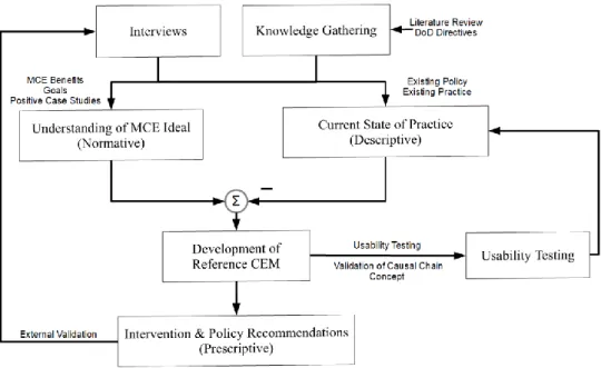
1.2 Research Approach
This research was characterized by two loops, both of which can be seen in Figure 1-1. In the first, expert interviews fed into an understanding of both the model-centric engineering ideal and the current state of the program management practice. The necessary differences between these two were used to generate the Reference Cause-Effect Mapping which in turn provided insight into
model-centric engineering vulnerabilities. These recommendations were then validated by further interviews. The other loop involved the usability testing, which was used to both assist in defining the current state of the practice, and in validating the causal chain concept.
Figure 1-1. Diagram of Research Approach
1.3 Research Questions
This work was guided by the following central research questions:
1. What new programmatic vulnerabilities will model-centric engineering introduce in defense acquisition programs?
2. Are causal chains a useful way to conceptualize and approach these vulnerabilities? 3. What methods can individuals and enterprises use to mitigate these new vulnerabilities?
1.4 Scope
This thesis primarily deals with the topic of vulnerability assessment as related to model-centric engineering acquisition programs, and defense acquisition in particular. It aims to provide a reference model and enable insight into the ways various exogenous factors impact model-centric defense acquisition programs and what can be done to mitigate these impacts. Additionally, it is
hoped that this work can help researchers in academia and policymakers in acquisition enterprises determine how best to structure acquisition programs to avoid certain vulnerabilities.
This thesis does not seek to directly tackle all of the challenges facing defense acquisition and bring us into a glorious new era of aligned incentives and good governance. Overcoming all of the challenges facing the defense acquisition system as it transforms into this new paradigm is a mammoth task that will require innumerable researchers, policymakers, industry partners, and uniformed service members to address. Even this is small compared to the major changes occurring in more general engineering and program management practices. While this thesis discusses some of these broader issues, it specifically seeks to contribute new findings that will hopefully play some small part in improving defense acquisition.
1.5 Research Contribution
This research provides several contributions to the body of knowledge concerning vulnerability assessment and the assessment of programmatic model-centric engineering vulnerabilities in particular. First and foremost, it advances the conceptualization of vulnerabilities as causal chains and uses results from usability testing to demonstrate the effectiveness of this conceptualization. The causal chain concept also enables new means of sorting and categorizing vulnerabilities, enabling the identification of effective interventions and heuristics. Second, this work explores and identifies programmatic vulnerabilities in model-centric engineering environments. While significant attention has been paid to the potential benefits of model-centric engineering and to its implementation challenges, much less consideration has been given to the new vulnerabilities that it introduces. This work is a step in that direction. Additionally, this work develops a typology of emergence and proposes a method for the creation of design patterns that jointly provide a common vocabulary for discussing the issues of emergence that can arise both within the model-centric engineering environment and in end-systems.
Tying these contributions together is the Reference Cause-Effect Mapping, which visually displays model-centric engineering vulnerabilities as causal chains, and allows the identification of a number of intervention points available to program managers.
Finally, this work provides general recommendations to program managers and several specific policy recommendations for MCE acquisition enterprises. These policies should serve to mitigate and obviate some of the model-centric engineering related vulnerabilities.
1.6 Thesis Structure
Chapter 1 lays out the goals, structure, and contributions of this work. Chapter 2 provides an overview of the defense acquisition system and of model-centric engineering. This includes both their history and their current status as it pertains to this work. Chapter 3 surveys the existing vulnerability assessment techniques and frameworks, including Cause-Effect Mapping. Chapter 4 lays out how Cause-Effect Mapping was applied to the model-centric engineering environment and what methods this research took to gather information and validate results, as well as the results generated by these methods. Chapter 5 explains emergent behavior and the use of design patterns in addressing such behavior, providing a common language for discussing emergence, and its potential relevance to model-centric engineering related vulnerabilities. Chapter 6 discusses general lessons and recommendations for program managers and model-centric engineering enterprises. Chapter 7 recaps the research findings, revisits the research questions, and discusses future work in this vein.
Chapter 2: Defense Acquisition and Model-Centric Engineering
Defense acquisition has existed long before model-centric engineering. Similarly, vulnerabilities have existed in both acquisition programs and in end-systems since the beginning of acquisition. Before proceeding into discussing the novel vulnerabilities related to model-centric engineering and how they can be mitigated, this chapter examines the historical development of defense acquisition (Section 2.1) and the transformation that it is undergoing. (Section 2.2).
2.1 What is Defense Acquisition?
Acquisition is the general term used by the United States Department of Defense (DoD) to refer to the lifecycle process of most engineered systems, as opposed to purely commercial off the shelf (COTS) products such as pencils or paper. The Defense Acquisition Glossary defines it as
“The conceptualization, initiation, design, development, test, contracting, production, deployment, integrated product support (IPS), modification, and disposal of weapons and other systems, supplies, or services (including construction) to satisfy DoD needs, intended for use in, or in support of, military missions.” [8]
Acquisition is an integral part of modern warfighting and is becoming even more important as engineered systems grow more complicated, technology advances, and the contexts of operation become more diverse. It is also something that has changed immensely over the decades (and centuries).
2.1.1 Historical Acquisition
For most of history and in most places, equipment, weapons, and military uniforms were provided by the soldiers themselves. In many places, this meant that social and economic class determined the type of soldier a person could be. The aristocracy were the commanders, the wealthy were the armored cavalry, the middle class were infantry, and the poor were often unable to serve at all. During this period, acquisitions largely did not exist. The Roman general Gaius Marius was the first to introduce standardized equipment provided by the state into the Roman Republic in 107 BC [9]. While this change, along with Marius’s other military reforms, is commonly credited as
being one of the primary causes for Rome’s later military successes, the practice did not find widespread acceptance in Europe until the Industrial Revolution.
Even when this did become the norm, such as during the 18th and 19th centuries [10], the acquisition process was mostly informal. It relied primarily on handwritten, relatively simple contracts, calling for the delivery of item X in quantity Y for cost Z by a certain date. In the US, these were often directly and specifically ordered by Congressional legislation, with minimal oversight over the actual fulfillment process. The general process was that a military officer or civilian member of the War Department would solicit a few bids, privately evaluate them, and then write a contract. Over the course of the 19th century, as technology improved, Congress got more directly involved in directing the application of these technological gains to military use, including standardized parts in firearms [11]. The implementation of these congressional commands had minimal oversight [12], however, and, in general, the traditional process was largely sufficient until the first World War.
2.1.2 Acquisition in the 20th Century
The world wars of the early 20th century resulted in innumerable lessons for the militaries of the world. Among them were the power of science and engineering in the design of military equipment, the importance of standardization, and the need for an infrastructure to support the design, development, and operation of increasingly complicated systems. These lessons, coupled with the results of the US and British militaries’ experiments in Operations Research, led to the development and application of first Systems Analysis [13] and then Systems Engineering [14] (though the exact timeline is fuzzy and also involved Bell Telephone Laboratories [15]). As the field of systems engineering coalesced, so too did the defense acquisition process, with a unified Department of Defense acquisition policy being put in place in over the course of the 1950’s and 1960’s [16]. This structure continued to evolve over the decades since, gradually becoming more unified [17].
The modern defense acquisition structure includes three interrelated components: the Joint Capabilities Integration and Development System (JCIDS); the Planning, Programming, Budgeting, and Execution System (PPBES); and the Defense Acquisition Process [18]s. Broadly speaking, JCIDS identifies the capabilities needed by the military and validates the requirements
for the system to be acquired. PPBES determines and allocates the resources necessary to successfully acquire the system. Finally, the Acquisition Process actually oversees the design, development, production, operation, and disposal of the system.
The Defense Acquisition Process is broken down into three phases (Pre-Systems Acquisitions, Systems Acquisitions, and Sustainment) and has three major milestone decisions (though, confusingly, these do not match up with the three phases). Throughout the process are a number of more minor decision points and reviews. Figure 2-1 shows a simplified timeline of this process. The full process is not easily displayed on a single page [19].
Figure 2-1. Simplified Diagram of the Defense Acquisition Process. From [18]
2.1.3 Problems in Acquisition
The resulting defense acquisition processes enabled the procurement of increasingly complicated and higher-performing assets over the course of the 20th century. They were unable, however, to control rapidly rising unit costs, particularly of major assets, as can be seen for surface naval combatants and fixed-wing fighter aircraft in Figure 2-2. This trend was noticed fairly early on, with Norman Augustine writing wryly in 1986 that “In the year 2054, the entire defense budget will purchase just one aircraft. This aircraft will have to be shared by the Air Force and Navy 3-1/2 days each per week except for leap year, when it will be made available to the Marines for the extra day.” [20]. While these trends are not unique to defense projects, they are particularly prevalent and severe in this domain [21].
Figure 2-2. Costs escalations over time for major us Defense assets. Reprinted from [1], [2]
The underlying causes of these issues are multitudinous. For instance, multiple incentive problems exist. On the military side, acquisition projects are typically managed by uniformed officers. These officers sometimes have little experience in large-scale project management. To further exacerbate matters, they are given little chance to acquire much experience as these posts typically last one to three years, where the acquisition project itself can span a period of five to twenty-five years. Additionally, their future promotion and career status is somewhat dependent on the apparent results in the acquisition project accomplished during their tenure. This can result in hurried
prototypes and rushed requirements definition, all of which can be overturned by the next program manager. [22].
On the industry side, different, but still harmful, incentives are pervasive. As mentioned earlier, most large military acquisition contracts are cost-plus, meaning there is little incentive to minimize costs. Additionally, there are typically few companies able to provide a given capability, resulting in monopolistic markets. Even when there is competition, it can be difficult to separate procurement from maintenance and operations, as the costs of switching from one company to another between lifecycle stages can be enormous. Private company careers typically are much longer than the military program managers, resulting in a disparity of experience and knowledge, further skewing incentives [23].
Just as these trends were initially noticed many years ago, efforts to curb the increases date back decades. Such efforts have taken multiple forms, including educative, with the founding of the Defense Acquisition University (DAU) in 1991 [24]; organizational, with the establishment of the Under Secretary of Defense for Acquisition in 1986 [17]; and enterprise-level, with the implementation of the Acquisition Improvement Program reforms following the Packard Commission [17] and the occasional switch to and from fixed cost and cost-plus contracts [24]. While these attempts at reform may have been ameliorative, the increase in costs has only continued to accelerate.
Some current efforts are focused externally to the acquisition programs. For instance, the International Council on Systems Engineering’s (INCOSE’s) Program Management – Systems Engineering Integration Working Group is working on “changing the acquisition game” including the incentives for underestimating costs and downplaying problems [25].
Beyond these attempts to more or less directly address the problematic incentives underlying these issues, others have attempted to work within the system, to provide tools and minor policy changes to curb the symptoms, if not cure the disease. Many of these tools have been developed by the systems engineering community, and include multi-attribute utility theory[26], multi-stakeholder tradespace exploration [27], epoch-era analysis [28], SysML [29], among others. While these tools have made not managed to reign in increasing costs and schedule delays as of yet, they have enable improved operational capability and reliability. There is reason to believe, however, that a more
complete embrace of these tools, along with increased model integration and usage, could, in fact, result in significant improvements to cost and schedule as well. This possibility, sometimes referred to as model-centric acquisition, is discussed in 2.2.
2.2 What is Model-Centric Engineering/Acquisition?
The ongoing transformation of acquisition has many aspects: Model-Based Systems Engineering (MBSE) [30], Digital Systems Model (DSM) [31], Digital Twin [32], Digital Model-Based Engineering (DMbE) [4], and Digital Thread [3], among others. Advances in computing, digital workflows, and multidomain-multiscale models are leading to new concepts and approaches for model-centric engineering ([3], [4], [30]–[32]. These terms all refer to different aspects of how these new capabilities may be integrated into modern engineering and acquisition practices. One such term, Model-Centric Engineering (MCE), has been defined as “An overarching digital engineering approach that integrates different model types with simulations, surrogates, systems and components at different levels of abstraction and fidelity across disciplines throughout the lifecycle.” [33]
MCE involves using integrated models across disciplines, subsystems, lifecycle stages, and analyst groups. It uses models as the “source of truth,” thereby reducing document handoff and allowing for more continuous evaluation of tradespaces and system performance. These in turn mean reduced communication time and rework in response to requirement changes, more reuse from project to project, an ability to push designs closer to their limit, and potentially predictive, rather than prescriptive, maintenance cycles.
While many engineering organizations are already testing and applying various aspects of MCE [32], [34], [35], implementation is not without its difficulties. More infrastructure is needed (such as model curation). Increased connectivity means the danger of improper access is heightened. Additionally, even once MCE practices are implemented, difficulties remain, as will be discussed in Chapter 4.
MCE is not solely applicable to defense acquisition. However, this work is primarily focused on MCE in defense acquisition, though some of the findings extend to other domains.
2.2.1 Aspects of MCE
MCE is not a singular, specific target to be reached. Rather it refers to the general transformation of the engineering environment and process. This transformation is and will be accomplished with a variety of methods, depending on the enterprise. Several notable aspects of MCE are discussed in this section, or order to provide the reader with a picture of the overall MCE concept.
2.2.1.1 Model-Based Systems Engineering
Model-Based Systems Engineering (MBSE) can be viewed as either the first wave of the broader MCE transformation or as a wholly independent endeavor. MBSE refers to the change of systems engineering methodology to rely on representing requirements and system architecture as models rather than as documents and drawings [36]. The push for MBSE has resulted in the rise of widely used tools such as SysML. The continuing success of MBSE likely contributed to the desire for the broader use of models that is MCE.
2.2.1.2 Digital Systems Models / Digital Thread
The Digital Thread (DTh) is analytic framework for integrating technical data, costs, predictions, and other accumulated knowledge over the course of design, development, and operation of a system. It is intended to provide ready access to usable information for decision makers during the design process. It includes tools such as tradespace analysis and visualization methods. The term “digital thread” is sometimes referred to by other terms, for example, Lockheed Martin Corporation has used the term Digital Tapestry [35]. The DoD defines DTh as:
“An extensible, configurable and component enterprise-level analytical framework that seamlessly expedites the controlled interplay of authoritative
technical data, software, information, and knowledge in the enterprise data-information-knowledge systems, based on the Digital System Model template,
to inform decision makers throughout a system's life cycle by providing the capability to access, integrate and transform disparate data into actionable
information.” [8]
The Digital System Model (DSM) is essentially the proposed product of DTh [37]. It is the integrated model of all technical data out of which individual Digital Twins will be constructed
and the technical grounding that the decision-making analytics of the DTh refers to. The DoD defines DSM as:
“A digital representation of a defense system, generated by all stakeholders that integrates the authoritative technical data and associated artifacts which define all aspects of the system for the specific activities throughout the system
lifecycle.” [8]
2.2.1.3 Digital Twin
A Digital Twin is an integrated model of an as-built system including physics, fatigue, lifecycle, sensor information, performance simulations, etc. It is intended to reflect all manufacturing defects and be continually updated to include wear-and-tear sustained by the system. The goal is to more effectively and safely manage the individual product as well as to facilitate investigations of potential design or operational changes on the health of the system. The DoD defines Digital Twin more specifically as:
“An integrated multiphysics, multiscale, probabilistic simulation of an as-built system, enabled by Digital Thread, that uses the best available models, sensor
information, and input data to mirror and predict activities/performance over the life of its corresponding physical twin” [8]
The Digital Twin can be used to simulate planned missions in order to improve mission design. Additionally, it could be used to predict when maintenance of various components is necessary, thereby having a more individually tailored maintenance schedule.
2.2.1.4 Model Integration and Composability
The descriptor “integrated” is used in different ways by different authors. Some seem to mean that the Digital Twin would be able to simultaneously simulate the system in multiple domains and at multiple scales [3]. Others seem to mean more that the integrated model would track all changes in components and propagate them out to all of the domain models [5]. The former is computationally more difficult but also would provide much greater gains in simulation accuracy.
Beyond the computational power required to integrate models of multiple domains and scales, there exists real issues of integration and composability. Different domains rely on fundamentally different assumptions and concepts. Often, even within a single domain, different conceptions of the world exist at different scales. In crack growth, for example, the very point of a crack is best modeled using quantum mechanics, the area surrounding this by molecular dynamics, and the overall material using continuum mechanics. While it is possible to develop algorithms to effectively combine these different scales into one model [38], this is nontrivial, must be done for each such “handoff,” and is epistemologically questionable [39]. Some of these issues are discussed further in Section 2.2.4.2
These technological difficulties are not the only hurtles posed by model integration and composability. Numerous organizational and human factors issues exist as well. Currently, many models are created by individuals or teams of analysts with specific uses in mind. In order to ensure composability, either standards would need to be implemented or models would need to be centrally created. Additionally, serious issues of trust exist when multiple models are composed together into one entity that no individual completely understands.
2.2.1.5 Semantic Web Technologies
Semantic Web Technologies (SWTs) refers to various extensions of the World Wide Web through standards. Several SWTs are of potential relevance to MCE, such as integrating the Web Ontology Language (OWL) with SysML, as proposed by JPL [40]. Figure 2-3 shows a diagram of some various SWTs and their level of abstraction. The general idea behind an integration of OWL and SysML, for instance, would be to make use of OWL’s ability to check consistency, satisfiability, entailments, completeness, and well-formedness. Active work by the Systems Engineering Research Center (SERC) is underway to extend JPL’s work [33].
Figure 2-3. Semantic Web Technology compared at various layers of abstraction. From [33]
2.2.1.6 Multidisciplinary Design, Analysis, and Optimization
One of the primary potential benefits of MCE is for a greater degree of system-level analysis and optimization. To accomplish this, it is necessary to be able to design, analyze, and optimize across disciplines. This is what the field Multidisciplinary Design, Analysis, and Optimization (MDAO) aims to do. Active work is being done to integrate single-discipline models, develop generic multidisciplinary models of various useful systems such as UASs [33], and develop better methods of visualization of the large tradespaces that result from such practices as this [41].
2.2.1.7 Model Curation
In order to address these hurtles, some researchers have proposed the creation of a model curation infrastructure [42], [43], that would both ensure that models could be effectively integrated and take whatever steps are necessary for ensuring the proper levels of trust exist in the models. Model curation involves a number of important functions, including setting and administering model-related policies; authenticating, preserving, classifying, and organizing models according to their metadata; and overseeing the data management practices in the enterprise. Some of the benefits and contributions of model curation can be seen in Table 2-1.
Table 2-1. Examples of benefits and contributions of model curation. From [44]
2.2.2 Examples of MCE Implementation
Aspects of MCE are being tested and implemented at a variety of points along the acquisition process in different organizations. A few examples of such implementations are discussed in this section.
2.2.2.1 F-35 Joint Strike Fighter
The development of the F-35 as part of the Joint Strike Fighter Program used many aspects of MCE, including “Man-In-The-Loop” simulations [45] and designing the control surface behavior [46], as well as a more general DTh that extended throughout the program [47]. Despite this, however, there was substantial difficulty in effectively modeling the software aspects of the system and this resulted in significant delays [48]. Overall, the F-35 may very well serve as a cautionary tale of the potential consequences of attempting to implement too many aspects of MCE too fast [49].
2.2.2.2 US Air Force and Naval Air Systems Command
The US Air Force and the US Naval Air Systems Command (NAVAIR) have been pushing towards further development and use of MCE practices on a variety of fronts. They are two of the primary supporters of the CREATE-AV program. CREATE-AV (Computational Research and Engineering Acquisition Tools and Environments for Air Vehicles) is one of the three parts of the broader CREATE program which over the past decade has sought to provide more integrated engineering toolsets for DoD acquisitions programs. In addition to tool development, the CREATE program has also involved shadowing various acquisition programs, involving multiple branches and sites [50].
The Air Force has been actively seeking to use CREATE-AV to construct a DTh that is continuous throughout the acquisition process [51]. This includes conceptual design (using the DaVinci program of CREATE-AV), detailed wing design (using either the fixed wing Kestrel or the rotary wing Helios), and airframe-propulsion integration (using Firebolt) [52].
Beyond this, NAVAIR has been actively involved with the development of the SWTs discussed in Section 2.2.1.5 [33], a vocal advocate of MCE at government-industry forums [5], and a supporter of using SERC research to develop graphical UAS CONOPS [53].
2.2.2.3 NASA
Within the NASA Jet Propulsion Laboratory (JPL) is Team X, an advanced concept design team charged with rapidly generating space mission concepts. While Team X has existed for more than 20 years, it has been continually improving. It was NASA’s original concurrent engineering team and has recently been a hub MCE testing, including visualization methods for teams of engineers with different disciplines. Additionally, JPL has been involved in developing useful ontologies for SysML and other MBSE processes [54] that have found uses elsewhere [33]. Most of these efforts exist on the early “Pre-Phase A” side of the acquisition process. JPL has even made these ontologies and tools publicly available (and are actively updating them as of time of writing) [55].
Outside of JPL, the NASA Sounding Rocket Program Office (SRPO) has been conducting a multi-year endeavor to develop their MCE capabilities across multiple NASA centers, both in terms of
tools and in trained engineers. This includes shadowing existing sounding rocket projects as a means of validating the MCE tools and processes across the entire acquisition lifecycle [56].
At Marshall Space Flight Center (MSFC), effort has been made to apply more MCE practices during the architecture phase, called NIMA (NASA Integrated Model-Centric Architecture [6]. Additionally, the multi-agency partnership known as the Community Coordinated Modeling Center (CCMC), based out of Goddard Space Flight Center (GSFC) seeks to provide coordinated verification of models, access to standardized data formats, and training on various models [57]. While they do not currently seek to set model integration standards in furtherance of MCE, they are a promising potential venue for such activities.
2.2.3 Benefits of MCE
The benefits of increased use of MCE are numerous and impact every stage of the acquisition lifecycle. Some of the most apparent are listed here:
Exploration of System Trade Space: Having an integrated model (whether unified or federated) enables more effective exploration of the system trade space and thus a greater degree of system level optimization [3], [5], [58].
Accelerated Production, Test & Evaluation: By having standards for models that stretch over the acquisition process, redundant effort in re-modeling between groups and lifecycle stages can be eliminated. An example of this would be “Direct CAD-to-CNC” prototyping, [3].
System/Component Life Estimation: Once a detailed integrated model of a system exists, it can be used to simulate operational environments and predict necessary maintenance. If the model was kept updated over the course of the life of the system, as in a Digital Twin, it could thereby enable a switch from prescriptive to predictive maintenance, reducing failure rates and extending the life of the system [59].
Design Reuse: Currently many designed components and subsystems remain locked in documents after their creation. What models exist in standard libraries often only model a particular domain of a component (such as its circuitry or thermal characteristics, for instance). Having an integrated
model of the entire system also means having integrated models of components, components that can be easily “drag-and-dropped” into a new system in the future [58].
2.2.4 MCE Implementation Barriers
Introducing MCE into an enterprise’s practices is not a trivial matter. Multiple barriers exist in implementation. Some of these are technical and some are more social or non-technical. Several examples of each category are discussed in this section.
2.2.4.1 Technical
Technical challenges are those that are primarily issues of current technological capabilities and engineering effort. Two particular such changes are:
Lack of standard operation architectures and common standards: Currently there are no extant standards for integrating models across domains, across levels of fidelity, or between organizations. This is a widely recognized problem [3], [5], [31], [58] that is not purely an issue of policy. Rather, significant technical expertise is required to enable data to be passed across domains or scales, due to the significantly different assumptions and conceptions of the physics at play, as discussed in Section 2.2.1.4.
Adequate Computer Processing Power: Even should models be effectively integrated, conducting full simulations of a trade space or operational performance may be difficult with current computing capabilities [3]. Even once simulated, displaying and processing the resulting information in a useful manner is a non-trivial problem [41].
2.2.4.2 Non-Technical
Non-technical challenges are those that are primarily cultural, economic, or social, rather than technology-based. This barriers to MCE implementation are well recognized [3], [4], [31]. Two particular categories are:
Intellectual Property (IP): [31]. IP in this context refers to any piece of information owned or held in some way by a person or organization. In the defense industry, this includes patents, software (or algorithms more generally), material data, business approaches, trade secrets, etc. A
key characteristic of IP is that, while information can be easily shared, value exists in information asymmetries (i.e. possessing information or IP that others do not). Since the construction of such a digital framework fundamentally requires the integration of IP from multiple sources, issues of valuation, compensation, and protection of IP arise [31]. The DoD is well aware of the IP issues raised by MCE and has previously discussed potential means around these barriers with representatives of industry [4], [5].
Knowledge Assessment (KA) and Cultural Inertia: KA refers to the assignment of validity to any particular piece of information or expertise. This can be a technical process, such as double-checking statistical methods used to evaluate the results of an experiment, or a more social process, such as deciding which news source to trust. KA issues include “buy-in” (i.e. trust) both by technical staff directly creating the models and by decision-makers in the acquisition and operation processes [60], as well as inter-model validity assessment in the cases of multiple models operating in the same domain (e.g. two crack-growth modeling methods). Some have argued that the issue of cultural inertia may be the primary barrier to implementing MCE [3]. Model Curation is one proposed solution to addressing these KA concerns [44]. Similarly to the IP barriers, the DoD is well aware of these KA challenges and already working to overcome them [4].
2.3 Program vs Project, End-Systems
As a brief aside, it is worth noting the differences between a program and a project. The Defense Acquisition Glossary defines a program as “A directed, funded effort that provides a new, improved, or continuing materiel, weapon or information system, or service capability in response to an approved need”. This is the definition of program that will be used in this work. A project, on the other hand is acknowledged as being synonymous with program in general usage, but more specifically defined as “a planned undertaking having a finite beginning and ending, involving definition, development, production, and logistics support (LS) of a major weapon or weapon support system or systems. A project may be the whole or a part of a program.” [8] MCE as a concept is applicable to both programs and projects. Additionally, many aspects of MCE are equally applicable to both, particularly as many projects exist within a program. Nonetheless, this work will focus on programs. Additionally, the term end-system is used throughout this work to refer to the system that an acquisition program is acquiring.
Chapter 3: Vulnerability Assessment
In Chapter 2, the increasing complexity of military end-systems and the resulting changes to the acquisition process were discussed. As this increase in complexity occurs, it becomes increasingly necessary to institute formal methods of assessing risks and vulnerabilities. In the modern era, there are many such methods, each with their own focus, strengths, and weaknesses. Prior to discussing MCE-related vulnerabilities and how they can be assessed in Chapter 4, this chapter defines exactly what vulnerabilities are and lays out several existing methods of vulnerability assessment. At the end of the chapter there is on a specific note about cybersecurity vulnerabilities.
3.1 Definitions
Numerous methods and frameworks for analyzing vulnerabilities, risks, and hazards exist. These three interrelated terms have different definitions depending on the field and on the method of analysis. In this work, a hazard refers to a system or environmental state that has the potential to disrupt the system. Examples include the existence of an iceberg at sea and tired operators. Hazards may not result in system failure, partly depending on the design of the system (such as the inclusion of an automated collision avoidance subsystem).
A vulnerability is the means by which the hazard might disrupt the system, thus it is through the vulnerability that the system is susceptible to the hazard. Vulnerabilities are best expressed as the causal series of events connecting a hazard to system failure. This is a generalization of common, field-specific usages of the term. MITRE’s Common Vulnerabilities and Exposures (CVE) database, for example, defines a vulnerability as “a weakness in the computational logic (e.g., code) found in software and some hardware components (e.g., firmware) that, when exploited, results in a negative impact to confidentiality, integrity, OR availability” [61]. The DoD defines a vulnerability as “The characteristics of a system that cause it to suffer a definite degradation (incapability to perform the designated mission) as a result of having been subjected to a certain level of effects in an unnatural (man-made) hostile environment.” [62] All of these definitions are related in the common dictionary definition: “Capability of or susceptibility to being wounded or hurt.” [63] In all these definitions, the same components can be seen: some structural means or “weakness” that can result in system disruption or “negative impact” if a hazard is present or the vulnerability is “exploited.” For example, the infamous Spectre security vulnerability is described
in CVE as “Systems with microprocessors utilizing speculative execution and branch prediction may allow unauthorized disclosure of information to an attacker with local user access via a side-channel analysis” [64]. This is a neat summary of the hazard (an attacker), the means (side-side-channel analysis using speculative execution and branch prediction), and the disruption (unauthorized disclosure of information).
Risk is a measure of the probability of a system disruption and the consequences of that disruption.
The common dictionary definition is simply “exposure to the chance of injury or loss.” [65] The DoD however defines it more closely to how engineers and scientists typically use the term: “Probability and severity of loss linked to hazards.” [62] The Defense Acquisition Glossary merely applies this definition to the acquisition domain: “Future event or condition that may have a negative effect on achieving program objectives for cost, schedule, and performance. Defined by 1) the probability (greater than 0, less than 1) of an undesired event or condition, and 2) the consequences, impact or severity of the undesired event, were it to occur.” [8] It is commonly expressed with just a statement of those two components: 1.25 deaths per 100 million vehicle miles. Sometimes risk is instead expressed as a multiplication of likelihood and consequence and can include other components such as detectability.
It should be noted that the above delineations between hazard, vulnerability, and risk are not universally recognized, either across or within disciplines [66], [67]. That said, the definitions stated above are how they shall be used in this work.
Two other relevant but blurry distinctions exist in the literature. The first is that between
assessment and analysis. These terms are often used interchangeably, including within the same
work (e.g. [68]–[70]). Similarly, this work will make no clear distinction between the two, other than that analysis will be used primarily regarding quantitative methods and assessment will be used primarily for qualitative methods. Since many methods include both quantitative and qualitative aspects, do not take this distinction to be any more than a general connotation.
The other distinction that requires discussion is that of method, framework, and technique. This is a distinction not previously made, to the author’s knowledge, but is worth making here. In this work, the word method will be used according its common usage as “a procedure… or way of doing something,” or “a manner or mode of procedure.” [71] Framework will be used to refer to a
method of assessing and analyzing hazards, vulnerabilities, and risks in a comprehensive manner, as well as determining appropriate mitigations and countermeasures. Examples of frameworks include Trusted Systems and Networks Analysis and Vulnerability Assessment & Mitigation Methodology. These and other frameworks are discussed in Section 3.2.2. A technique, on the other hand, will refer to a method for analyzing a particular set of hazards, vulnerabilities, or risks. Examples of techniques include Fault Tree Analysis and the Structured What-If Technique. These and other techniques are discussed in Section 3.2.1.
3.2 Methods of Vulnerability, Hazard and Risk Assessment
Numerous methods of analyzing vulnerabilities, hazards, and risks have been developed over the years. Some were developed with particular issues in mind. Fault-Tree Analysis was invented to be used on the Minuteman Guidance System, for instance [72]. Whatever, their original intent however, many of them have come to be used widely and are often parts of an engineer’s undergraduate education.
In general (though not always), the frameworks consist of four distinct parts.
1. Threat/Hazard Identification and Assessment 2. Vulnerability Identification and Assessment 3. Risk Identification and Assessment
4. Mitigation and Prevention Identification and Assessment
In this way, vulnerability assessment is one part of a more general framework, typically occurring after hazards have been identified but before risks are analyzed [73]. Techniques are often used within frameworks as the means of identifying and/or analyzing specific vulnerabilities or risks. Some existing techniques and frameworks are discussed in this section.
3.2.1 Existing Techniques
In this section, several risk and vulnerability analysis techniques are discussed. Many of these techniques are used as part of the broader frameworks discussed in Section 3.2.2. For an explanation of the distinction between techniques and frameworks, see Section 3.1.
3.2.1.1 Fault Tree Analysis and Event Tree Analysis
Fault Tree Analysis (FTA) is a deductive, top-down analysis method where a failure mode is identified and all the possible causes of that event are laid out in sequences until the exogenous hazards are reached. Logic gates are used to connect the various hazards and intermediary events. An example FTA may be seen in Figure 3-1. Probabilities may be assigned to each hazard and thus a cumulative probability of the failure calculated. FTA is thus quite proficient in investigating the cause of failures afterwards, but is limited in its ability to prospectively identify all possible hazards. Additionally, it is somewhat limited by its arbitrary stopping point (i.e. where one chooses to define an event as an exogenous hazard).
Figure 3-1. Simplified Fault-Tree Analysis of the sinking of the Titanic
Event Tree Analysis (ETA) is essentially an inverted FTA. Instead of starting from a failure and working backwards to a hazard, a hazard is selected and logic gates are used to assess potential consequences. This method is useful for predicting potential failures rather than determining the cause of a previous one. It suffers from some of the same limitation as FTA. Additionally, it fails to examine the consequences of multiple concurrent hazards.
3.2.1.2 Failure Modes and Effects Analysis (FMEA)
FMEA and the closely related Failure, Modes, Effects, and Critical Analysis (FMECA), are inductive methods, similar to ETA, that seek to tabulate all possible failures and then assessing their severity, probability, detectability, and criticality. It excels at thoroughness but suffers from an inability to easily assess multiple failures simultaneously. Additionally, its tabular format can be difficult to read. An example FMECA can be seen in Figure 3-2.
Function Dispense amount of cash requested by customer
Potential Failure Mode
Does not dispense cash Dispenses too much cash
Potential Effect(s) of Failure Customer dissatisfied Incorrect entry to demand deposit system Discrepancy in cash balancing Bank loses money Discrepancy in cash balancing Severity Rating 8 6 Potential Cause(s) of Failure
Out of Cash Machine jams Power failure during transaction Bills stuck together Denominations in wrong trays Occurrence Rating 5 3 2 2 3 Current Process Controls Internal low-cash alert Internal jam alert None Loading procedure (riffle ends of stack) Two-person visual inspection Detectability Rating 5 10 10 7 4
Risk Priority Number 200 240 160 84 72
Criticality 40 24 16 12 18
Figure 3-2. Portion of an FMECA. Figure adapted from [74]
3.2.1.3 Systems Pathology
Systems Pathology (as it pertains to systems engineering) is an attempt to apply the medical research concept of Systems Pathology [75] to engineered systems. The basic idea is to study the architecture of the system and determine what dysfunctions, or “pathologies,” may occur based on that architecture [76]. Some example pathologies that have been identified, along with the architectures that give rise to them are [77]:
Cyberpathologies (dysfunctions of feedbacks) Rheopathologies (dysfunctions of systems flows)
Cyclopathologies (dysfunctions of cycling, oscillations)
Heteropathologies (dysfunctions of hierarchy or modular structure) Hapsopathologies (dysfunctions of network structure or dynamics) Teratapathologies (dysfunctions in developmental pathologies) Stathopathologies (dysfunctions in stability states)
This is a relatively new technique that is still actively being developed and formalized [78].
3.2.1.4 Systems-Theoretic Hazard Analysis (STPA)
STPA takes a rather different approach and conceptualizes systems as control loops, as can be seen in Figure 3-3. The goal of STPA is to avoid focusing on exhaustively tabulating all vulnerabilities and attempting to quantitatively calculate probabilities. These can be difficult to do accurately for a system of any significant size or for risks that are sufficiently rare. Instead, STPA attempts to ensure that appropriate monitors and controls are in place for each component of the system (including its operators) so that any hazard is detected and addressed before it can cause a failure. In this way, it seeks to eliminate vulnerabilities while relying primarily on a qualitative, rather than a quantitative, assessment.
Figure 3-3. Example STPA Diagram. Image from [79]
The STPA process consists for four iterative steps [79]:
1. Establish the system engineering foundation for the analysis and for the system development
2. Identify potentially unsafe control actions
3. Use the identified unsafe control actions to create safety requirements and constraints 4. Determine how each potentially hazardous control action could occur.
Most of vulnerability analysis methods fail to directly grapple with the problem of blame. Humans, engineers and program managers included, have a tendency to assign blame for a failure to someone or something other than themselves. FTA, ETA, and FMECA can enable this by allowing for an arbitrary “stopping point” (i.e., where the previous step in the causal chain is deemed the initiating hazard). In the Titanic FTA presented in Figure 3-1 of Section 3.2.1.1, for instance, why did the causal deconstruction halt there? Were the designers of the rudder actually at fault? Or
were the engineering standards poorly written? Were the owners of the boat at fault for installing too few lifeboats or should the government set a minimum required number of lifeboats? By adjusting the bounds of the analysis, it is easy to place blame on whomever the analyst desires.
STPA avoids this by (a) not assigning a specific “cause” of a failure and (b) by having every part of the system responsible for monitoring the other parts. Despite this, as the creators of STPA themselves acknowledge, the method has been criticized for its lack of a neat, one-page explanation of the causes of an accident [79].
3.2.1.5 Cause-Effect Mapping
Cause-Effect Mapping (CEM), is a vulnerability identification method developed at MIT (where it was originally called “Cause and Effect Mapping”) [80]. CEM has been previously applied to a maritime security system [80] (as seen in Figure 3-4), energy grids [70], and supply chains [81]. It consists of a mapping of causal chains that connect an exogenous hazard to a system degradation or failure, termed a terminal event. Causal chains are a series of events, with each event causing or being an integral part of the cause, or the next “link” in the chain. Each chain represents a vulnerability, sometimes called a vulnerability chain in order to emphasize that vulnerabilities are not discrete events. Terminal events are broadly defined and include any form of value loss.
Figure 3-4. Example CEM for a maritime security system. From [82]
Similar to FTA, CEM is easily read in either direction, but it also allows for the simultaneous consideration of multiple failures and multiple hazards. Another difference between the two is that CEM allows for causal loops, such as in Figure 3-4. Unlike STPA, however, it also does not necessitate causal loops can be seen in the supply chain CEM shown in Figure 3-5.
![Figure 2-1. Simplified Diagram of the Defense Acquisition Process. From [18]](https://thumb-eu.123doks.com/thumbv2/123doknet/14098447.465319/25.918.112.815.388.583/figure-simplified-diagram-defense-acquisition-process.webp)
![Figure 2-2. Costs escalations over time for major us Defense assets. Reprinted from [1], [2]](https://thumb-eu.123doks.com/thumbv2/123doknet/14098447.465319/26.918.117.592.148.393/figure-costs-escalations-time-major-defense-assets-reprinted.webp)
![Figure 2-3. Semantic Web Technology compared at various layers of abstraction. From [33]](https://thumb-eu.123doks.com/thumbv2/123doknet/14098447.465319/32.918.125.747.122.500/figure-semantic-web-technology-compared-various-layers-abstraction.webp)
![Table 2-1. Examples of benefits and contributions of model curation. From [44]](https://thumb-eu.123doks.com/thumbv2/123doknet/14098447.465319/33.918.115.486.149.634/table-examples-benefits-contributions-model-curation.webp)

![Figure 3-3. Example STPA Diagram. Image from [79]](https://thumb-eu.123doks.com/thumbv2/123doknet/14098447.465319/45.918.152.613.127.591/figure-example-stpa-diagram-image-from.webp)
![Figure 3-4. Example CEM for a maritime security system. From [82]](https://thumb-eu.123doks.com/thumbv2/123doknet/14098447.465319/47.918.140.594.122.470/figure-example-cem-maritime-security.webp)
![Figure 3-5. Example CEM for a supply chain. From [81]](https://thumb-eu.123doks.com/thumbv2/123doknet/14098447.465319/48.1188.135.993.117.744/figure-example-cem-supply-chain.webp)
![Figure 3-6. Trusted Systems and Network Analysis Methodology. From [89]](https://thumb-eu.123doks.com/thumbv2/123doknet/14098447.465319/53.918.146.666.114.534/figure-trusted-systems-network-analysis-methodology.webp)
