Publisher’s version / Version de l'éditeur:
Vous avez des questions? Nous pouvons vous aider. Pour communiquer directement avec un auteur, consultez la
première page de la revue dans laquelle son article a été publié afin de trouver ses coordonnées. Si vous n’arrivez pas à les repérer, communiquez avec nous à [email protected].
Questions? Contact the NRC Publications Archive team at
[email protected]. If you wish to email the authors directly, please see the first page of the publication for their contact information.
https://publications-cnrc.canada.ca/fra/droits
L’accès à ce site Web et l’utilisation de son contenu sont assujettis aux conditions présentées dans le site LISEZ CES CONDITIONS ATTENTIVEMENT AVANT D’UTILISER CE SITE WEB.
Design and Construction of Vessels Operating in Low Temperature Environments
[Proceedings], 2007
READ THESE TERMS AND CONDITIONS CAREFULLY BEFORE USING THIS WEBSITE. https://nrc-publications.canada.ca/eng/copyright
NRC Publications Archive Record / Notice des Archives des publications du CNRC : https://nrc-publications.canada.ca/eng/view/object/?id=9aaf4014-d976-43f6-bba9-afe63ddac061 https://publications-cnrc.canada.ca/fra/voir/objet/?id=9aaf4014-d976-43f6-bba9-afe63ddac061
NRC Publications Archive
Archives des publications du CNRC
This publication could be one of several versions: author’s original, accepted manuscript or the publisher’s version. / La version de cette publication peut être l’une des suivantes : la version prépublication de l’auteur, la version acceptée du manuscrit ou la version de l’éditeur.
Access and use of this website and the material on it are subject to the Terms and Conditions set forth at
Lifeboat operational performance in cold environments
The Royal Institution of Naval Architects Design & Construction of Vessels Operating in Low Temperature Environments
LIFEBOAT OPERATIONAL PERFORMANCE IN COLD ENVIRONMENTS
António Simões Ré, Institute for Ocean Technology, National Research Council, Canada
Brian Veitch, Ocean Engineering Research Centre, Memorial University of Newfoundland, Canada
ABSTRACT
Shipping and offshore petroleum industry operations in Arctic and sub-Arctic regions have to account for an environment characterized by cold temperatures, remote locations, and a wide range of sea ice cover. To do so successfully, environmental factors must be addressed at the concept design stage. The environment affects operations on multiple levels: special structural design and steel grades to withstand ice loads under cold temperatures; robust propulsion systems to ensure reliability under propeller-ice interaction; winterization measures such as heating, insulation of fire mains and cooling water pipes, arrangement of access ways, icing, and extended low light conditions; and the human factors of working in a cold, remote, dark environment for extended periods. Design and operation in such environments requires special knowledge, skill and technology. This applies as well to the design and operation of the vessels’ safety systems, including evacuation craft. An evacuation scenario must be executed in the ice conditions that prevail at the time of the emergency. In order to design an appropriately robust emergency response capability, it is essential to know what to expect of evacuation systems in terms of their utility in the presence of ice. This paper presents the results of an experimental campaign that investigated the performance capabilities of several lifeboats in ice. A series of model scale experiments was done in an ice tank to examine the effects of ice concentration, floe size and thickness on the lifeboats’ abilities to launch and make way through the ice. Three different hull forms were tested to see how changes in shape might change performance. Likewise, changes in the delivered power were investigated in terms of simple performance benchmarks. Conclusions drawn from the model tests are presented and discussed.
1. INTRODUCTION
Most emergency response procedures and equipment have been designed for temperate regions and open water conditions. Indeed, evacuation craft on ships and offshore petroleum installations are overwhelmingly of the conventional lifeboat sort, whether configured as free-fall or davit launched. Such craft are clearly not suitable for operation in heavy ice cover, if for no other reason than they cannot be launched into the water. Still, even if used in cold regions, they are capable in open water conditions and have marginal utility when the ice conditions are not onerous, including during the freeze-up and break-up seasons that typically bracket the most severe winter conditions. The main aim of the work presented here is to provide some quantitative guidance on the utility of lifeboats in marginal ice conditions, including the expected limits of their abilities. The performance limits of conventional lifeboats define the minimum performance requirements of complementary innovative evacuation systems that can extend existing emergency response capabilities.
Hazards that may give rise to the need to evacuate, and the impact of such hazards on the means of evacuation, are not dealt with here, although they are recognized as being important, as is the integration of means of evacuation and rescue in the broader context of emergency response.
2. EXPERIMENTS
2.1 Scope
The main objective of the experiments reported here was to define the operating limits imposed by ice conditions on a conventional lifeboat in terms of ice concentration, ice floe size, and ice thickness. In addition, the effects of additional lifeboat power and different hull forms were investigated. The limits constitute a boundary beyond which there is a gap in evacuation capabilities that presents an opportunity for innovation.
The main set of tests involved a pair of 1:13 scale models of a generic lifeboat, fitted with propulsion systems that could be operated at 4 distinct power settings. Tests with these models were done in a range of ice concentrations from approximately 4/10ths up to 9/10ths, and in ice of two thicknesses and two floe sizes. A second set of tests was done with three models of three different lifeboat types. These three models, which were built at a larger scale (1:7), were also tested in a range of ice conditions and at two separate power settings, although the range of test conditions was somewhat smaller than in the first set of tests. The main goal of the second set of tests was to evaluate the effect on performance of changes in the lifeboats’ hull form.
2.2 Setup: Models
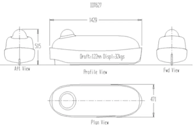
Sketches of the three larger models are presented in Figures 1, 2 and 3, showing a conventional TEMPSC style displacement craft, a free-fall type lifeboat, and a hard chine TEMPSC displacement craft, respectively. All three vessels were of similar size, as indicated by the 1:7 scale model particulars in Table 1. Tests done with the smaller scale models (1:13) used the same geometry as the conventional lifeboat shown in Figure 1.
All the models were built in two sections (hull and canopy) using molded glass reinforced plastic. Each of the 1:7 scale models was fitted with an electric motor run on batteries. Two power settings were available. The main power setting corresponded to the power required to meet the regulatory requirement that the vessel make 6 knots in open water (IMO 1997), which was slightly different for each hull form. The second power level corresponded to the maximum available and was similar for each vessel. Using bollard pull as a benchmark, the second power setting provided an increase of about 10% to 25% over the main power setting. Each model was driven by a single screw. A small video camera was fitted in the coxswain’s position and transmitted to a tank-side monitor that was used during the tests by a technician who operated the vessel by remote control. Each model was also fitted with motion sensing instruments, markers for optical tracking, remote control hardware, a radio transmitter, and a PIC acquisition system. More details about these models can be found in Mak et al. (2005) and Simões Ré et al. (2006).
The two smaller models were geometrically similar to each other (and to the model in Figure 1), but were configured differently for the two test types: one for launch tests and the other for powering tests. Instrumentation and outfit included a motor and battery pack, a propeller and rudder, and a wireless transmitter and camera. The maximum shaft speed used in the tests corresponded to a full scale forward speed in calm water of 6 knots. The model launch system was fitted to the carriage of the Ice Tank and consisted of a conventional twin falls davit arrangement with dual motors and winches. This was used to lower the model into the water from its stowed position, where the falls were released and the lifeboat was driven away at full power, with control being exercised by the remote control coxswain. Powering tests could not be done with the same model as there was insufficient room for the larger motor and battery pack. Likewise, this meant that the higher powered model was unable to be launched remotely and so started in the water. A fuller description of the models is given elsewhere (Simões Ré & Veitch 2003 and Simões Ré et al. 2003).
Figure 1. Conventional TEMPSC lifeboat model (627).
Figure 2. Free-fall lifeboat model (628).
Figure 3. Hard chine TEMPSC lifeboat model (681).
Table 1. Model particulars, 1:7 scale.
Condition IOT627 IOT628 IOT681 Length overall (m) 1.429 1.607 1.429 Length on water line(m) 1.381 1.521 1.353
Breadth overall (m) 0.456 0.413 0.507 Mass (kg) 32.85 32.92 29.15 Longitudinal centre of mass (m) 0.720 0.709 0.740 Vertical centre of mass (m) 0.186 0.214 0.221
2.3 Setup: Ice
All the experiments were done in the Ice Tank at the Institute for Ocean Technology. Separate ice sheets were grown for the thinner and thicker ice conditions. For the initial set of tests with the small model of a conventional lifeboat, the ice sheets were approximately 25mm and 50mm thick, corresponding to full scale conditions of 325mm and 650mm. For a given ice sheet, separate pools were cut for the smaller and larger floes. For each pool, the ice cover was cut into appropriate floe shapes and then a strip of ice was removed to reduce the concentration to the initial test conditions (typically 9/10ths). The remaining floes were distributed over the pool’s surface area. Tests were then done in the pool for the given conditions, after which the concentration was adjusted and testing continued.
A similar process was followed for the ice sheet preparations in the tests with the larger lifeboat models. In those tests, the ice sheets were approximately 46mm thick, corresponding to a full scale ice thickness of approximately 325mm.
2.4 Test Plan
The small model used in the initial tests was tested first in thinner ice. 20 launches were made into a pool with smaller floes, followed by 12 launches into another pool with larger floes. Ice concentration in the smaller floe pool started at 9/10ths and was reduced during the test series stepwise to 4/10ths. The corresponding range for the larger floe pool was 7/10ths to 4/10ths. Following the series of tests in thinner ice, a second series of tests was done using the same model, but in thicker ice. 10 launches each were made into separate pools of smaller and larger floes over a range of concentrations.
After the launch and sail-away tests described above, the second 1:13 scale model of a conventional lifeboat was used for powering tests. The model was calibrated to provide approximately two, three, or four times the bollard pull compared to the power available from the basic configuration (that is, the power required to make 6 knots in calm water). The powering configurations are denoted, from basic to highest, as T1, T2, T3, and T4,
respectively. 35 powering tests were done, consisting of 17 in the thinner ice sheet and 18 in the thicker ice sheet. Two pools were used, one for smaller floes and the other for larger floes. The range of ice concentration conditions was narrower in these tests as the focus was on the conditions that presented difficulty for the model with the basic installed power.
The three larger scale models were also tested in similar ice conditions consisting of combinations of floe size and ice concentrations. In addition, for several ice conditions, the model was tested at two different power settings. A total of 76 tests were done, 45 in smaller floes and 31 in larger floes.
3. RESULTS
3.1 Ice Concentration, Thickness, and Floe Size
The main measure of performance used throughout the tests was simple: was the lifeboat able to launch and sail away through the pack ice? Each test was given a pass or fail grade based on whether the boat made it through a distance of 75m (full scale).
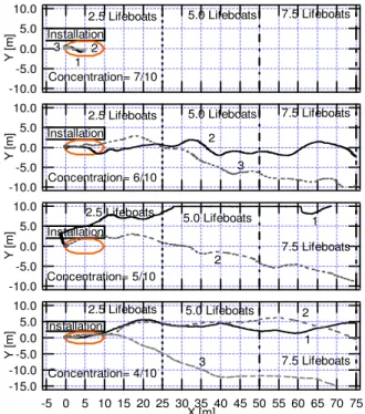
Results are presented in Figures 4 to 7 in terms of the plotted paths taken by the lifeboat during each test. For example, Figure 4 shows the path taken by the lifeboat in each of the tests done in the thinner ice and smaller floes. A separate plot is given for each of the six concentrations, starting at the top with 9/10ths. In that top plot, two very short paths are presented, corresponding to the unsuccessful transits associated with the two test launches done in that condition. Similar results are shown in the second plot for the three unsuccessful transits in 8/10ths concentration. The third plot shows the paths taken by the lifeboat in each of four successful transits in 7/10ths conditions. Similarly successful transits are shown in the remaining plots of Figure 4 for the tests in lower concentrations. With reference to the figure, as the concentration decreases, the paths taken by the boat become increasingly more direct.
Figure 5 shows the corresponding results for the tests done in thinner ice and larger floes. Figures 6 and 7 show results of tests done in thicker ice and smaller and larger floes, respectively. Table 2 summarizes the results in terms of the simple pass (P) or fail (F) grades. The numbers in parentheses in the table refer to the number of tests done in those conditions. The results of repeated tests for each condition were consistent: all passed or all failed. Conditions became impassable at concentrations of between 6/10ths to 8/10ths, depending on the thickness and ice floe size, with thicker ice and larger floes being more difficult to transit than thinner ice and smaller floes. 3.2 Powering
The second model in the main test series had an adjustable setting to provide different thrust values, corresponding approximately to a doubling, tripling and quadrupling of the basic power configuration. Results of these tests are summarized in Table 3, again using pass and fail grades as the basic performance measure. For each combination of concentration, floe size and ice thickness, tests were done at one or more power settings. For each condition, results using the basic power setting are shown in the bottom right, results from the highest power (T4) are in the upper left, and the intermediate
powers, T2 and T3, are shown in the lower left and upper
right corners, respectively. The results show that very significant increases in power yielded only marginal improvements in terms of extending the operational limits, for example from 6/10ths to 7/10ths.
-10.0 -5.0 0.0 5.0 10.0 Y [ m ] Installation
2.5 Lifeboats 5.0 Lifeboats 7.5 Lifeboats
1 2 Concentration= 9/10 -10.0 -5.0 0.0 5.0 10.0 Y [ m ] Installation
2.5 Lifeboats 5.0 Lifeboats 7.5 Lifeboats
Concentration= 8/10 1 2 3 -10.0 -5.0 0.0 5.0 10.0 Y [ m ] Installation
2.5 Lifeboats 5.0 Lifeboats 7.5 Lifeboats
Concentration= 7/10 1 3 4 5 -10.0 -5.0 0.0 5.0 10.0 Y [ m ] Installation
2.5 Lifeboats 5.0 Lifeboats 7.5 Lifeboats
Concentration=6/10 1 2 3 4 5 -10.0 -5.0 0.0 5.0 10.0 Y [ m ] Installation
2.5 Lifeboats 5.0 Lifeboats 7.5 Lifeboats
Concentration= 5/10 1 2 3 -10.0 -5.0 0.0 5.0 10.0 Y [ m ] 75 70 65 60 55 50 45 40 35 30 25 20 15 10 5 0 -5 X [m] Installation
2.5 Lifeboats 5.0 Lifeboats 7.5 Lifeboats
Concentration= 4/10
1 2 4
Figure 4. Paths: thin ice, small floes.
-10.0 -5.0 0.0 5.0 10.0 Y [ m ] Installation
2.5 Lifeboats 5.0 Lifeboats 7.5 Lifeboats
Concentration= 7/10 1 2 3 -15.0 -10.0 -5.0 0.0 5.0 Y [ m ] Installation 2.5 Lifeboats 5.0 Lifeboats 7.5 Lifeboats Concentration= 6/10 1 2 3 -10.0 -5.0 0.0 5.0 10.0 Y [ m ] Installation
2.5 Lifeboats 5.0 Lifeboats 7.5 Lifeboats
Concentration= 5/10 1 2 3 -10.0 -5.0 0.0 5.0 10.0 Y [ m ] 75 70 65 60 55 50 45 40 35 30 25 20 15 10 5 0 -5 X [m] Installation
2.5 Lifeboats 5.0 Lifeboats 7.5 Lifeboats
Concentration= 4/10
1 2
3
Figure 5. Paths: thin ice, large floes.
-10.0 -5.0 0.0 5.0 10.0 Y [ m ] Installation
2.5 Lifeboats 5.0 Lifeboats 7.5 Lifeboats
Concentration= 7/10 1 2 3 -10.0 -5.0 0.0 5.0 10.0 Y [ m ] Installation
2.5 Lifeboats 5.0 Lifeboats 7.5 Lifeboats
Concentration= 6/10 2 3 -10.0 -5.0 0.0 5.0 10.0 Y [ m ] Installation 2.5 Lifeboats 5.0 Lifeboats 7.5 Lifeboats Concentration= 5/10 1 2 -15.0 -10.0 -5.0 0.0 5.0 10.0 Y [ m ] 75 70 65 60 55 50 45 40 35 30 25 20 15 10 5 0 -5 X [m] 2.5 Lifeboats 5.0 Lifeboats 7.5 Lifeboats Concentration= 4/10 1 2 Installation 3
Figure 6. Paths: thick ice, small floes.
-10.0 -5.0 0.0 5.0 10.0 Y [ m ] Installation 2.5 Lifeboats 5.0 Lifeboats 7.5 Lifeboats Concentration= 7/10 1 2 3 -10.0 -5.0 0.0 5.0 10.0 Y [ m ] Installation
2.5 Lifeboats 5.0 Lifeboats 7.5 Lifeboats
Concentration= 6/10 1 2 -10.0 -5.0 0.0 5.0 10.0 Y [ m ] Installation
2.5 Lifeboats 5.0 Lifeboats 7.5 Lifeboats
Concentration= 5/10 1 2 -10.0 -5.0 0.0 5.0 10.0 Y [ m ] 75 70 65 60 55 50 45 40 35 30 25 20 15 10 5 0 -5 X [m] Installation
2.5 Lifeboats 5.0 Lifeboats 7.5 Lifeboats
Concentration= 4/10
1 2
3
Figure 7. Paths: thick ice, large floes.
Table 2. Pass and fail results for the launch tests. Nominal Ice
concentration [10ths] 4 5 6 7 8 9
nominal thickness
nominal
floe size Pass or Fail
325mm smaller P(3) P(3) P(5) P(4) F(3) F(2)
325mm larger P(3) P(3) P(3) F(3)
650mm smaller P(3) P(2) P(2) F(3)
Table 3. Powering effects: conventional lifeboat. Ice concentration [10ths] thick [mm] floe size [-] 5 6 7 8 2F 325 smaller 3P 5P 2P 3P4P 3F 2P 3P 325 larger 3P 3P 2P 3P3F 2P 2P1F 650 smaller 2P 2P 1P1F 3F Power legend 2P 1P1F 3F 3F T4 T3 650 larger 2P 1P 2P2F 3F T2 T1 3.3 Hull Form
Results of tests with the three larger models are shown in Table 4, where the model numbers corresponding to the boats are 627 for the conventional TEMPSC, 628 for the free-fall, and 681 for the hard chine boat. These tests were done in similar conditions as those done with the smaller models, that is, in pack ice comprised of smaller and larger floes with concentrations from 5/10ths to 8/10ths. For each combination of ice thickness, floe size, and ice concentration, the table has two spaces, one on the right for the lower power (or thrust) T1, and the other at left for
the higher power, T+.
The limiting ice concentration for all of the lifeboats was usually 7/10ths. Repeated tests done with the hard chine boat in 6/10ths concentration and small floes in the basic power configuration had some mixed results – that is, 5 successful transits and 1 unsuccessful test. Similarly mixed results were observed for the conventional TEMPSC in larger floes at both 6/10ths and 7/10ths. Overall, the lifeboats exhibited roughly similar behaviour; there was no clear evidence that one hull form performed better or worse than the others.
Table 4. Hull form effects (325mm full scale).
Ice concentration [10ths]
Floe size model
5 6 7 8 627 6P 6P 1F 628 7P 7P 1F 1F small 681 6P 5P1F 2F 2F 627 2P 2P1F 5P2F 628 3P 4P 3P 2F Power Legend large 681 3P 4P T+ T1
The conventional lifeboat is 627, the free-fall lifeboat is 628, and the hard chine TEMPSC is 681.
Maneuvring characteristics were also examined in both open water and in ice using turning circle diameter as a performance benchmark. All three lifeboats had larger turning circles in open water than in the ice conditions in which tests were done, and although the diameters were different in open water for the three hull forms, they were almost the same in ice.
Results of additional tests done in combinations of pack ice and waves for all three models were reported by Sudom et al. (2006). The results indicated that the presence of waves in combination with pack ice helped the vessel make way through the ice, even in relatively high ice concentrations that would otherwise have prevented progress in calm conditions. The models’ success in transiting pack ice in waves was found to depend mainly on the wave period and ice concentration, rather than on hull form.
4. CONCLUSIONS AND DISCUSSION
An experimental campaign using model scale lifeboats was carried out to investigate the performance of evacuation craft in a range of ice conditions, including combinations of pack ice concentration, thickness and floe size. These tests were used to estimate the limiting ice conditions for these evacuation systems. In addition, the effects of additional power and different hull form were investigated to determine if these might have mitigating effects on the performance limits.
In terms of ice conditions, concentrations of 6/10ths to 8/10ths were found to be impassable, with the limit being reached at lower concentrations for thicker ice and larger floes. Substantial increases in powering extended the performance limits in ice only marginally, although it is likely that increased power would offer more significant improvements to the lifeboats’ open water performance in waves. As for the different hull forms, there was no discernable difference in performance during transits through pack ice, either in calm water or combined with waves, nor during maneuvering in pack.
These conclusions must be taken in the context of the experiments and their associated limitations. Ice conditions in the field are more complicated than those used in the tests. For example, ice conditions can be dynamic, such as when pack ice comes under compressive wind loads, causing its concentration to increase. As well, the tests did not look at ice features such as ridges or rubble embedded in intact ice sheets, because the evacuation craft examined are not capable of operating in such conditions; nor did the tests consider the capability of the evacuation craft in brash ice conditions that might occur in fairways or ports where ice is managed by icebreakers or similar vessels.
Still, the results provide some benchmarks of the utility of such craft in terms of pack ice conditions. By extension, they provide an indication of the requirements
of either alternative or complementary evacuation systems for use in ice-covered waters.
The decision drivers for alternative or complementary evacuation systems are much broader than the performance requirements in pack ice, and it is worthwhile in this context to consider some of these. In general terms, the key aim of personnel with respect to evacuation systems in ice is similar to those in open water: access, embark, and launch an evacuation vehicle; get clear of the emerging hazard and survive until rescued; and do so in prevailing environmental and hazard scenarios without undue risk of harm.
From this overall goal, an evacuation system can be defined in other terms, such as functionality, operability, flexibility, and availability. Target functionality includes a specification of the environmental conditions in which the evacuation system must work, as well as issues such as number of personnel to be evacuated, and the distances involved. It also includes the identification of credible hazard scenarios under which evacuation might be required. Operability covers issues such as ease of use and extends to training; flexibility covers the interface between the functional requirements and the operational logistics; and availability includes issues such as maintenance requirements and reliability. To be fit for purpose, the solutions to these various needs must be compatible in a single coherent design.
What that design solution might look like depends on the specific situation. Limiting the discussion for the moment to petroleum installations, one example is a situation involving a very large number of offshore personnel working on a group of linked near shore installations in shallow water. This might be best served by fixed infrastructure that has multiple functions, including routine personnel transportation as well as evacuation. Roads in various configurations might fit this need, including ice roads, roads on pylons, in-filled causeways, and tunnels, to name a few. Another situation, say in relatively deep water and for a complement of only some 10s of personnel, might lend itself to consideration of means such as helicopters, or perhaps less conventional aircraft. While the use of roads in the first situation might negate the need for other forms of evacuation, the use of helicopters in the latter probably does not.
Indeed, there are many situations that would probably be well served by a surface vehicle of some sort. Conventional lifeboats have marginal utility once the ice season begins as they are not suited to operating in many of the ice conditions that would be common to most ice-covered regions. For heavy ice conditions, wheeled or tracked vehicles are possible solutions and have already been used for various functions in Arctic conditions. For lighter ice conditions, or during the freeze-up and break-up periods of the ice season, the weight of an ice surface vehicle will limit its utility. In these circumstances, a light weight vehicle that can operate on even rather thin ice, or a vehicle with amphibious capabilities might be an attractive solution. Various craft of this sort have already
been used for roles in ice-covered water, including hovercraft for icebreaking and fan boats for search and rescue.
Space limitations prevent a fuller discussion of the merits and demerits of these and other evacuation system alternatives, but even this notional assessment highlights that there are a range of options that could be adopted or adapted to a wide range of circumstances. The best solution for a given situation will be that which stands up to a full assessment and is found to be most fit for the purpose.
ACKNOWLEDGEMENTS
The financial support of Natural Resources Canada’s Program of Energy Research and Development (PERD) is acknowledged with gratitude.
REFERENCES
IMO. 1997. International life-saving appliance code (LSA Code). International Maritime Organization.
Mak, L., Simões Ré, A., Sullivan, M. and Kennedy, E. 2005. Assessment of totally enclosed motor propelled survival craft (TEMPSC) hull design performance in ice covered waters. Institute for Ocean Technology
Technical Report TR-2005-06, St. John’s, 34 p.
Simões Ré, A. and Veitch, B. 2003. Performance limits for evacuation systems in ice. Proceedings, Ports and
Oceans under Arctic Conditions, Trondheim, 10 p.
Simões Ré, A., Mak, L., Kennedy, E. and Veitch, B. 2006. Performance of lifeboats in ice. Proceedings,
Icetech, Banff, 4 p.
Simões Ré, A., Veitch, B., Elliot, B. and Mulrooney, S. 2003. Experimental evaluation of lifeboat evacuation in ice environments. Institute for Marine Dynamics
Technical Report TR-2003-03, St. John’s, 25 p.
Sudom, D., Kennedy, E., Ennis, T., Simões Ré, A. and Timco, G. W. 2006. Testing of evacuation system models in ice-covered water with waves. Canadian
Hydraulic Centre Report CHC-TR-37, Ottawa, 41 p.
AUTHOR BIOGRAPHIES
António Simões Ré is a Senior Research Officer at the National Research Council’s Institute for Ocean Technology.
Brian Veitch teaches Ocean and Naval Architectural Engineering at Memorial University of Newfoundland.
![Table 3. Powering effects: conventional lifeboat. Ice concentration [10ths] thick [mm] floe size [-] 5 6 7 8 325 smaller 2F 3P 5P 2P 3P4P 3F 2P 3P 325 larger 3P 3P 2P 3P3F 2P 2P1F 650 smaller 2P 2P 1P1F 3F Power legend 2P 1P](https://thumb-eu.123doks.com/thumbv2/123doknet/14175214.475192/6.918.89.445.126.411/table-powering-effects-conventional-lifeboat-concentration-smaller-smaller.webp)
