Publisher’s version / Version de l'éditeur:
Vous avez des questions? Nous pouvons vous aider. Pour communiquer directement avec un auteur, consultez la première page de la revue dans laquelle son article a été publié afin de trouver ses coordonnées. Si vous n’arrivez pas à les repérer, communiquez avec nous à PublicationsArchive-ArchivesPublications@nrc-cnrc.gc.ca.
Questions? Contact the NRC Publications Archive team at
PublicationsArchive-ArchivesPublications@nrc-cnrc.gc.ca. If you wish to email the authors directly, please see the first page of the publication for their contact information.
https://publications-cnrc.canada.ca/fra/droits
L’accès à ce site Web et l’utilisation de son contenu sont assujettis aux conditions présentées dans le site LISEZ CES CONDITIONS ATTENTIVEMENT AVANT D’UTILISER CE SITE WEB.
Inter-Noise 2007: [Proceedings], pp. 1-10, 2007-08-28
READ THESE TERMS AND CONDITIONS CAREFULLY BEFORE USING THIS WEBSITE. https://nrc-publications.canada.ca/eng/copyright
NRC Publications Archive Record / Notice des Archives des publications du CNRC :
https://nrc-publications.canada.ca/eng/view/object/?id=926e4d89-bdac-4761-9c4c-29ebea2228c2 https://publications-cnrc.canada.ca/fra/voir/objet/?id=926e4d89-bdac-4761-9c4c-29ebea2228c2
NRC Publications Archive
Archives des publications du CNRC
This publication could be one of several versions: author’s original, accepted manuscript or the publisher’s version. / La version de cette publication peut être l’une des suivantes : la version prépublication de l’auteur, la version acceptée du manuscrit ou la version de l’éditeur.
Access and use of this website and the material on it are subject to the Terms and Conditions set forth at
On the mobility of joist floors and periodic rib-stiffened plates
http://irc.nrc-cnrc.gc.ca
O n t h e m o b i l i t y o f j o i s t f l o o r s a n d p e r i o d i c
r i b - s t i f f e n e d p l a t e s
N R C C - 4 9 6 9 4
M a y r , A . R . ; N i g h t i n g a l e , T . R . T .
A version of this document is published in / Une version de ce document se trouve dans: Inter-Noise 2007, Istanbul, Turkey, August 28-31, 2007, pp. 1-10
The material in this document is covered by the provisions of the Copyright Act, by Canadian laws, policies, regulations and international agreements. Such provisions serve to identify the information source and, in specific instances, to prohibit reproduction of materials without written permission. For more information visit http://laws.justice.gc.ca/en/showtdm/cs/C-42
Les renseignements dans ce document sont protégés par la Loi sur le droit d'auteur, par les lois, les politiques et les règlements du Canada et des accords internationaux. Ces dispositions permettent d'identifier la source de l'information et, dans certains cas, d'interdire la copie de documents sans permission écrite. Pour obtenir de plus amples renseignements : http://lois.justice.gc.ca/fr/showtdm/cs/C-42
INTER-NOISE 2007
28-31 AUGUST 2007 ISTANBUL, TURKEY
On the mobility of joist floors and periodic rib-stiffened plates
Andreas R. Mayra
The University of Liverpool
Acoustics Research Unit, School of Architecture L69 3BX, Liverpool, UK
Stuttgart University of Applied Sciences 70174 Stuttgart, GERMANY
Trevor R.T. Nightingaleb
National Research Council Canada, Institute for Research in Construction, Building M-27, Montreal Road, Ottawa,
Ontario, K1A 0R6 CANADA
ABSTRACT
This paper presents measured and predicted mobilities for two types of point-excited periodic structures. The first is constructed from an isotropic material (Plexiglas) and the connection between the rib and plate reasonably approximates a line (over the frequencies of interest). The second is a real joist floor where the orthotropic wood products forming the sheathing and ribs are point-connected (over much of the frequency range of interest). The paper begins by showing for both structures there is significant variation in the drive point mobility with position, and that the drive point mobility is bounded. An infinite plate defines the upper bound while a beam of infinite length defines the lower bound. Additionally, when the drive point is above a rib the location relative to the adjacent screws becomes an important factor. Thus, ordinary mobilities for an infinite plate and beam are inadequate to accurately model the system. The plate rib structure is also modelled using the analytical formulation for an assembly of finite-sized plate strips coupled at a series of parallel junctions. There is good agreement between the predicted drive point mobility and measurements in the frequency range where the plate rib junctions approximate a line connection.
1 INTRODUCTION
In wood framed buildings floors are formed by fastening orthotropic wood sheathing to a series of joists spaced at a regular interval. The sheathing is typically fastened to the joist using only screws so the resulting system is a complex periodic orthotropic point-connected plate/rib structure. Being able to accurately estimate the power injected by mechanical sources, and the resulting vibration response of the floor, is critical to predict flanking transmission for sources of structural excitation, such as footfalls, washers, dryers, etc.
This paper begins by examining how location of the drive point affects the real part of the mobility (which is the component associated with power injection) for two rib-stiffened structures having different properties and construction details. Later a model is presented and measured and predicted results are compared. In this paper the portion of the plate between the ribs will be referred to as being the “bay”.
2 EXPERIMENTAL SET-UP
Two structures were evaluated. First was a well-defined structure constructed from a homogeneous and isotropic material with well-known material properties – Plexiglas. Second, was a joist floor constructed from typical wood materials – chipboard sheathing and
a
Email address: andreas.mayr@hft-stuttgart.de
b
spruce joists. The construction details and method of measuring the mobility of these structures are now described.
2.1 Plexiglas structure
Both the plate and the ribs were cut from Plexiglas – a homogeneous and isotropic
material with well-characterized material properties [1]. The plate has dimensions
2.42 x 1.21 m with a thickness of 11.9 mm. Plexiglas ribs, 235 mm deep and 18.7 mm thick, nominally spaced 40 mm on center, divided the 1.2 x 2.4 m plate into six bays as shown in Figure 1. Sixteen equally spaced bolts fastened each rib to the plate and approximate a line connection [2] in the frequency range of interest (100-5000 Hz). The plate was mounted vertically and supported on two point contacts so that boundary conditions at all four edges can be considered “free”.
41.3 40 Rib 5 Rib 4 Rib 3 Rib 2 Rib 1 23.5 E A I B H C G D F
Figure 1: Sketch showing the periodic structure used to evaluate the spatial dependence of the drive point mobility and the model. All
dimensions are given in centimetres.
The mobility at each of the nine points (labeled A through I in Figure 1) was measured in turn using a Wilcoxon F4 integrated shaker and impedance head. The force was applied via small indenter (6.6 mm diameter) to approximate the assumption of an infinitely small indenter implicit in most modeling approaches. Estimates were corrected for the effect of the mass below force gauge (which is dominated by the mass of the mounting screw).
2.2 Wood joist floor
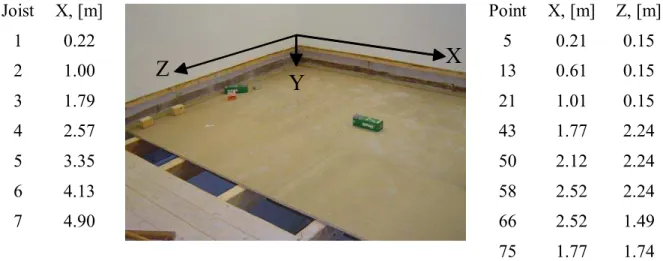
The wood joist floor measured - shown in Figure 2 - is 4.55 m x 4.95 m and has 21 mm chipboard sheathing supported by seven Norwegian spruce joists 0.096 m x 0.192 m x 4.55 m spaced 0.78 m on center. The sketch in Figure 1 showing the periodic Plexiglas structure can be used for the periodic joist floor structure but with the dimensions given in Figure 2. The chipboard sheathing, consisted of panels with the dimension 0.9 m x 2.05 m, were joined together by tongue and grooves, and were secured to the joists using only screws (spaced 0.20 m on center); no glue was used. A massive concrete test frame supported the ends of each joist (approximately 0.15 m) without additional fixing and intermediate layer. However, the boundary conditions for this floor construction are not obvious. No ceiling was installed.
The mobilities were measured with a calibrated impulse hammer. The dynamic condition corresponded with many practical situations where mechanical sources rest on receiver structures without fixing. Even if the sources are rigidly mounted to the basic structure at some points, there might be many more contact points which are not.
Joist X, [m] Point X, [m] Z, [m] 1 0.22 5 0.21 0.15 2 1.00 13 0.61 0.15 3 1.79 21 1.01 0.15 4 2.57 43 1.77 2.24 5 3.35 50 2.12 2.24 6 4.13 58 2.52 2.24 7 4.90 66 2.52 1.49
Z
X
Y
75 1.77 1.74 Figure 2: Picture of wood joist floor used to evaluate the spatial dependence of the drive point mobility and themodel; Global floor orientation is indicated - Table with coordinates of joists and considered points on the floor.
3 EXPERIMENTAL RESULTS
3.1 Plexiglas structure
Figure 3(a) shows the real part of the drive point mobility of the Plexiglas structure is a function of location relative to a stiffening rib. It is important to note that there are four measurement pairs (A&I, B&H, C&G, and D&F) which are symmetric about position E and have nominally identical distances (0, 0.05, 0.10 and 0.15 m) to the nearest adjacent rib. There is no such symmetry and common distance to the perimeter of the ribbed-plate.
Inspection of Figure 3(a) indicates the measured mobility is very similar for positions that have a nominally identical distance to an adjacent rib. For this structure with free boundary conditions, it is the distance to an adjacent rib that is most important in determining the mobility – the distance to the edge of the plate perpendicular to the ribs is of much less importance.
When the drive point is well away from a stiffening rib (more than 0.10 m), i.e., near the center of the bay (Points D, E & F), the measured mobility is approximated by that of an uncoupled infinite plate of the same thickness.
The figure also indicates that the mobility decreases with decreasing distance to an adjacent rib. When the drive point is located immediately above a rib (positions A and I) the measured mobility is reasonably approximated, below about 1000 Hz, by the mobility of an uncoupled infinitely long beam of the same depth and width as the rib. Above about 1000 Hz, the measured mobility increases with increasing frequency, and as suggested by the trend of the mobility for a point 0.05 m away, will tend to the mobility of a an uncoupled infinite plate at high enough frequencies.
To examine the importance of source position relative to a stiffening rib the mobilities of Figure 3(a) were normalized by that of an infinite plate, and plotted as a function of the source distance normalized by the bending wavelength. The results are shown in Figure 3(b). There are two very important observations. First, when the ratio of the source distance to bending wavelength is greater than unity the plate can be considered as an infinite uncoupled plate because the ribs have minimal effect. Second, when this ratio is less than one-quarter (0.25) the ribs play prominently and the mobility is considerably less than that of an uncoupled infinite plate. This had been observed by Lin and Pan [3] from theoretical calculations. For small enough values the mobility, as shown by Figure 3(a), will tend to that of a rib. For ratios between ratios one-quarter and one, the normalized mobility will oscillate
about unity (first greater than that of the infinite plate and then less, and so on) as it converges to unity. Measurement of bending wavenumbers on a wood joist floor [4] also suggest when the distance to joist was more than one-quarter bending wavelength the joists had little effect on the wavenumber measured parallel to the joists.
Figure 3: Plexiglas structure – (a) measured real part of the drive point mobility as a function of distance from a 235mm deep rib. Shown for comparison are estimates for infinite plates and beams of the same thickness
from thin plate theory. (b) normalised mobility as a function of the non-dimensional distance between the drive point and the 235mm deep rib.
3.2 Wood joist floor
Similar observations can be made for the wood joist floor shown in Figure 2. Figure 4(a) indicates the mobility for points located near the center of a bay (more than 0.15 m from a joist) is reasonably approximated by that of an uncoupled infinite plate of the same thickness. Further, the mobility in the low frequencies decreases as the distance to an adjacent joist decreases and the mobility on a joist, in the low frequencies, is reasonably approximated by that of an uncoupled infinitely long beam with the same depth and width. Figure 4(b) shows the measured mobilities normalized to that of an infinite plate and plotted as a function of distance normalized to the bending wavelength.
Figure 4: Wood joist floor - (a) measured real part of drive point mobility as a function of distance from a joist Shown for comparison are estimates for infinite plates and beams of the same thickness from thin plate theory.
(b) mobilities plotted as a function of the non-dimensional distance between the drive point and the nearest joist.
The results for the orthotropic wood joist floor are similar to those of the isotropic Plexiglas structure – namely, when the ratio of the distance to the bending wavelength is less
than one-quarter the joist behaviour dominates and the mobility is considerably less than that of an uncoupled infinite plate. Whereas when this ratio is greater than one-quarter the joists have minimal effect and the chipboard panel can be considered as an uncoupled infinite plate. The fact that the chipboard is fastened to joists using a series of screws spaced 0.20 m apart leads to the chipboard being effectively point-connected to the joists at the high frequencies and line-connected at the low frequencies. Hence, in addition to the difference observed from Figure 4, the location relative to the nearest fixing point (where the chipboard panel is screwed to the joist) becomes an important factor when the drive point is above a joist.
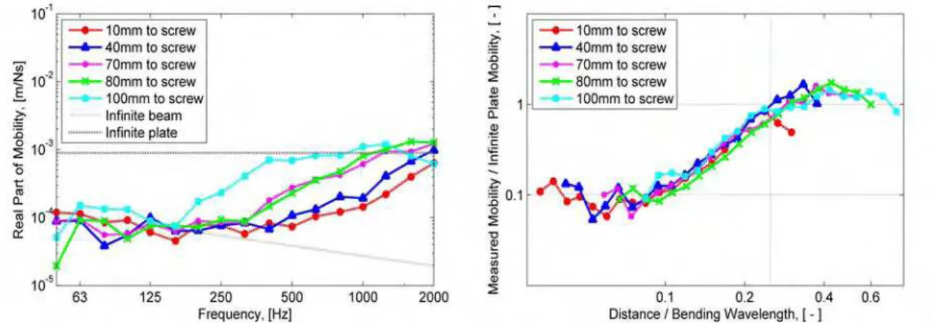
Figure 5: Wood joist floor - (a) measured real part of drive point mobility for points located above a joist as a function of distance from a screw. (b) mobilities plotted as a function of the non-dimensional distance between
the drive point and the adjacent fixing point
To examine the importance of distance to the next fastener (screw) the mobility for positions above a joist was measured at various distances along a draw-way line from a screw. Figure 5(a) shows that the mobility is a function of distance to the nearest fastener. At low frequencies and small distances from the fastener, infinite beam behaviour is quite evident. However, with increasing distance and/or frequency the mobility tends to rise towards the characteristic plate mobility. In Figure 5(b) the measured mobilities are normalized to that of an infinite plate and plotted as a function of the distance to the nearest screw normalized by the bending wavelength. The behaviour observed in Figure 5 for distance from a fastener is precisely the same that was observed in Figure 4 for the distance from a joist.
The similarities between Figure 4 and Figure 5 allow generalization of the observations. Because it is the distance between the observation point and the nearest fastener that is important, we can state when the ratio of this distance to the bending wavelength is less than one-quarter the joist dominates the floor response and the mobility is considerably less than that of an uncoupled infinite plate. When the ratio is greater than one-quarter the joists have minimal effect and the chipboard panel can be considered as an uncoupled infinite plate.
From Figures 3(b), 4(b) and 5(b) a master curve can be concluded which could be used for predictions to engineering accuracy based on simple infinite beam and plate mobilities. In terms of the distance/bending wavelength axis, the infinite beam assumption could be used below 0.1, infinite plate above 0.25, and in between a straight-line interpolation.
4 MODELLING
The measured results shown in the preceding figures indicate that the ordinary mobilities cannot be used to predict the drive point mobility at an arbitrary point on a rib-stiffened
structure. At best ordinary mobilities of the rib and plate in isolation might be used to provide bounds for the system mobility, but a general prediction method is required.
4.1 Theoretical Approach
The ribbed plate is modeled as a number of plate elements coupled at a series of parallel junctions as shown in Figure 6. The plate to which the ribs are attached is considered to be formed from a series of smaller finite-sized plates defined by the plate/rib junctions.
F
y x z
Figure 6: The ribbed plate is modelled by a series of finite-sized plates coupled at a number of parallel plate junctions.
Thin plate theory is adopted so the effects of shear deformation and rotary inertia are not considered. Plate and ribs are treated similarly. Both are considered plate elements having a vibration response that can be described by a series expansion assuming simply supported boundary conditions along the plate edges perpendicular to the junction line as shown in Figure 7.
Z
X
Y
Simply supported boundary condition
Simply supported boundary condition
Arb itrar y bo unda ry c ondi tion Arb itra ry b ound ary cond itio n v Lz
Figure 7: Boundary conditions applied to each plate.
Uncoupled edges of the plate and ribs parallel to the z-direction are assumed to have free boundary conditions. For a plate element parallel to the x-z plane, the solution is obtained by substitution of Eqn(1) into the equations of motion [1], [5],
t j z n x jk n z e L n e A t z x v n π ω =
∑
∞ = sin ) , , ( 1 (1)In the Eqn(1), v represents the plate displacement, An the complex amplitude, kn the
wavenumber in x-direction and Lz the plate width in z-direction.
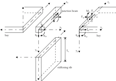
In the model each junction consists of two plates and a stiffening rib coupled by a junction beam, as shown in Figure 8. The boundary conditions at the junctions are described by equilibrium and continuity conditions for the equations of motion and are identical to those given elsewhere [6]. These equilibrium and continuity conditions are a uniform along the plate/rib junction, because a line-connection is assumed.
The model assumes the plate structure is driven by a point force normal to the plate surface, as shown in Figure 6. To manage continuity and displacement conditions at the point
of excitation an additional junction is introduced at the drive point location. In this paper the model approach will be referred to as “semi-modal finite plate” approach.
xp yp zp Fyp Fxp Fzp Mzp αzp ηp ζp ξp αzb ηb ζb ξb bay bay junction beam stiffening rib Lx x0 y0 z0
Figure 8: Model of the joint showing forces, moments and displacements used in the boundary conditions.
4.2 Predicted Results
This section presents measured and predicted results for the mobility of the wood joist floor shown in Figure 2. As noted above the model assumes two sets of boundary conditions. The first set and easiest to satisfy is the requirement for a free boundary at the uncoupled edge of a plate parallel to the global z-direction. This condition is approximated well by the free edges of the chipboard at X = 0 and X = 4.95 m. The second set and more difficult to satisfy in practice are the simply supported boundary conditions for edges parallel to the x- and y-direction. In reality the boundary condition of the chipboard at Z = 0 and Z = 4.55 m is free. The actual boundary condition for the joists is unknown, but probably it is closest to being “simply supported” rather than “clamped” or “free”.
The predictions for floor mobility assume the chipboard had density 668 kg/m3 and was
isotropic with modulus of elasticity of 2.0E9 N/m2, Poisson’s ratio of 0.30, and a shear
modulus of 2.0E8 N/m2. The material properties of Norwegian spruce were not available so
it was assumed that those of Engelmann spruce were a reasonable approximation.
Figure 9: Wood joist floor - measured and predicted real part of the drive point mobility for positions that are located in a bay. Shown for comparison are estimates for infinite plates and beams of the same thickness from
When the drive point is located in the bay midway between joists (Positions 13 and 50), the predicted results are in good agreement with measurements, as shown by Figure 9. For these locations, the ordinary mobility of an infinite plate made of the same material provides a reasonable approximation.
As noted earlier in this paper the measured mobility is a function of the distance to the closest fastener, and when the distance is greater than one-quarter of the bending wavelength in the chipboard, the measured mobility is largely determined by the mobility of the chipboard – the joists have minimal effect. This was true for measurement positions directly above a joist as well as for those in a joist bay.
Since the model assumes that the plate(s) and rib are line-connected it is not possible to account for point-connected behaviour analytically. A pragmatic solution is necessary to more accurately predict the mobility of points located above a joist.
Based on the results of Figure 3(b), Figure 4(b) and Figure 5(b), it is assumed the mobility is determined by nearest point at which the plate and rib are rigidly coupled, that is
the nearest screw. If the measurement point is a distance ξ to the nearest screw, then the
mobility at the measurement point above the joist can be approximated by the mobility of an
“equivalent” point offset a distance ξ from the screw in the direction normal to the axis of the
joist, as shown in Figure 10.
Figure 10: Sketch showing set-up for pragmatic solution to account for point-connected behaviour in prediction of drive point mobilities located above a joist.
Screw Distance ξ Point of Measurement Equivalent Point for prediction
Figure 11 shows predictions for Positions 43, 58, 66 and 75 located above a joist for various distances from a screw, when the approximate method described above is used. Here the positions are well away from an edge of the floor and the agreement with measurements is quite good. With the exception of Position 75 (nominally 10 mm from the screw) the offset used in the prediction was smaller than the measured distance, typically less than 20 mm. This might be explained by recognizing that the distance that really matters is the distance between the measurement point and the nearest point on the chipboard where the chipboard and joist move together in phase. The presence of a finite contact area around fastener will tend to reduce this distance, and might explain why the distance used in the calculations is less than that to the screw head. Regardless, Figure 11 clearly demonstrates there is promise for this approach.
Figure 11: Wood joist floor - measured and predicted real part of the drive point mobility for points located above a joist as a function of distance from a screw. Shown for comparison are estimates for infinite plates
and beams of the same thickness from thin plate theory.
Figure 12 shows the measured mobility and two predictions for points above a joist that are 0.15 m from an edge of the floor. In the first prediction it is assumed that the chipboard plate and the joists are perfectly line-connected, and the results are a gross underestimation of the mobility. Note that here both the measured and predicted mobilities are less than that of an infinite beam of the same dimension. The reason is that the measurement point is very close to the edge of the floor and measured mobility is strongly affected by the boundary conditions (of no vertical displacement caused by the concrete test frame).
The second prediction employs the approximate approach described above, and results in a vast improvement in the accuracy of the prediction. Results above about 200 Hz for Point 5 (Figure 12(a)) and 400 Hz for Point 21 (Figure 12(b)) might be considered to be very good. Results below this are poor, presumably because of the importance of the boundary conditions which are not known and are not matched by the prediction model.
Figure 12: Wood joist floor - measured and predicted real part of the drive point mobility for positions that are located above a joist and near the supported edge of the floor. (a) Point 5 - (b) Point 21;
5 DISCUSSION AND CONCLUSIONS
Measurement results presented in this paper demonstrate that the drive point mobility of a rib-stiffened structure is strongly affected by the location of the drive point relative to the ribs. Results were nearly identical for both the homogeneous and isotropic Plexiglas structure and the anisotropic wood joist floor when normalized to that of an infinite plate, and plotted as a function of the source distance normalized to the bending wavelength.
Measurements indicated the mobility of both structures could be approximated by that of the ordinary mobility of a plate having the same thickness, when the drive point is more than one-quarter wavelength from a rib. Measurements for positions directly above a joist indicated that mobility was also function of distance from a screw when subfloor sheathing is not glued to the joists, i.e., it is point-connected.
A more generally applicable statement would be, when the distance between the measurement point and nearest fastener (screw) is less than one-quarter wavelength the mobility will be strongly affected by the presence of the joist below.
This enables us to state that when the fastener spacing is at least one-half wavelength there will be some points above the joist (for which the quarter wavelength condition is not satisfied) and the joist will have minimal effect on the mobility. This half wavelength criterion marks the transition between line and point-connected behaviour and has been used in SEA models employing an impedance approach for modeling point-connected plates.
Observations made in this paper may have implications for those interested in transfer mobilities as the quarter wavelength criterion might also define the radius around an excitation point in which all points might be considered highly correlated and “effectively” acting at a single point. The criterion might also suggest that when two excitation points are operating in different bays separated by a joist, the joist will play prominently when one or both points is closer than a quarter wavelength to the nearest fastener. However, when the distance to nearest fastener is greater than a quarter wavelength the joists might not have to be included in a model, and the complex structure is reduced to a simple plate. Obviously, there is much work to be done here.
The first author gratefully acknowledges the financial support provided by EPSRC, UK for measurements on the joist floor.
6 REFERENCES
[1] I. Bosmans 1998 Analytical Modelling of Structure-Borne Sound Transmission and Modal Interaction at Complex Plate Junctions. PhD Dissertation, KU Leuven, Belgium. [2] S. Schoenwald, T.R.T. Nightingale, 2000, "Measurement of structural intensity on plate structures," Canadian Acoustics, Vol. 29(3), September, Proceedings Issue of Canadian Acoustics, pp. 102-103.
[3] Tian Ran Lin, Jie Pan, 2006, “A closed form solution for the dynamic response of finite ribbed plates,” J. Acoust. Soc. Am. Vol. 119(2), pp. 917-925.
[4] T.R.T Nightingale, R.E. Halliwell, G. Pernica, 2004, “Estimating in-situ material properties of a wood joist floor: Part 1 – Measurements of the real part of the bending wavenumber,” Journal of Building Acoustics, Vol. 11(3), pp. 175-196.
[5] E. Rébillard and J.-L. Guyader, 1995, “Vibrational behaviour of a population of coupled plates: hypersensitivity to the connexion angle”, Journal of Sound and Vibration,
188(3), 435-454.
[6] I. Bosmans, T.R.T. Nightingale, 2001,“Modeling vibrational energy transmission at bolted junctions between a plate and a stiffening rib," Journal of the Acoustical Society of America, Vol. 109(3), pp. 999-1010