B.S., Material Science and Engineering (2005) Tsinghua University
Submitted to the Department of Mechanical Engineering in Partial Fulfillment of the Requirements for the Degree of
Master of Science in Mechanical Engineering at the
MASSACHUSETTS INSTITUTE OF TECHNOLOGY June 2007
(0 Massachusetts Institute of Technology 2007. All rights reserved. I I
/
Signature of A uthor ... ...C ... Department of Mechani al Engineering
May 10, 2007
Certified by ... . , .. . .. .- ... .' ... Tomasz Wierzbicki Professor of Applied Mechanics Thesis Supervisor
A ccepted by ... r ... %... . . . .
-Lallit Anand Professor of Mechanical Engineering e Chairmnan, Department Committee on Graduate Students
Ballistic Resistance of Multi-layered Steel Shields
by Min Huang
Ballistic Resistance of Multi-layered Steel Shields
byMin Huang
Submitted to the Department of Mechanical Engineering
on May 10, 2007, in Partial Fulfillment of the Requirements for the Degree of Master of Science in Mechanical Engineering
ABSTRACT
In this thesis, the ballistic resistance of multi-layered steel shields against projectile impact at the sub-ordnance velocity is evaluated using finite element simulations. Eight types of projectiles of different weight and nose shapes are considered, while the multi-layered shields studied are the double-layered shield with the plates initially in contact, the double-layered shield with the plates spaced, the double-layered shield with the plates welded together and the BRAS shield. According to our simulation results, the double-layered shields are able to improve the ballistic limit by 7.0% - 25.0% under the
impact of the flat-nose projectile, compared to the monolithic plate of the same weight. Under the impact of the conical-nose projectile, the double-layered shields are almost as capable as the monolithic plates. For the double-layered shields with different material combinations, the best configuration is that with the upper layer of high ductility material and the lower layer of low ductility material under moderate detrimental impact. The configuration results in some 25% gain in the ballistic limit. The worst configuration is that with the upper layer of low ductility material and the lower layer of high ductility material. The BRAS shield, which has been shown to resist blast loading is proved to be equal to the monolithic plate in perforation resistance against the flat-nose projectile. This research helps resolve the long outstanding issue of the ballistic resistance of the multi-layered configurations.
Thesis Supervisor: Tomasz Wierzbicki Title: Professor of Applied Mechanics
Acknowledgement
First of all, I would like to express my heartful gratitude to Professor Tomasz Wierzbicki for his guidance, support and great vision during my two years graduate study at MIT, and for providing me with Research Assistantship all long. Throughout my life, I haven't met such a wonderful person as an advisor. Also, I wish to thank Professor Parks, my co-advisor, for his valuable guidance and encouragement.
To my colleagues at the Impact and Crashworthiness Lab, Post Doctor Xiaoqing Teng, Dr. Yuanli Bai, Dr. Liang Xue, Dr. Carey Walter, Dr. JongMin Shim and others, thank you for all your help and creating a pleasant working environment.
I am sincerely indebted to my parents-in-law, my uncle and my aunt-in law and my
friends Simon Li, for their financial support during my studying abroad.
This work was partially supported by the ONR/MORI grant on "Development of Adaptive Blast Resistant Structures" and by the ARO grant on "Effect of Strain Rate on Fracture".
Contents
1. Introduction...21
2. Problem Description...25
2.1 Computational models... 25
2.2 Plasticity and fracture models for tested materials...33
2.2.1 Weldox 460 E steel...33
2.2.2 Domex Protect 500 steel...35
3. Ballistic Resistance of the Double-layered Shields with Two Plates Spaced and in Contact... 41
3.1 Heavy flat-nose projectile ... 41
3.2 Heavy conical-nose projectile... 47
3.3 Light flat-nose projectile...52
3.4 Light conical-nose projectile...57
3.5 Compared with experimental results...61
4. Ballistic Resistance of the Double-layered Shields with Different Combinations of M aterials...65
4.1 Heavy conical-nose projectile... 65
4.2 Heavy flat-nose projectile...77
4.3 Light conical-nose projectile...86
5. Ballistic Resistance of Blast Resistance Adaptive Sandwich...101
5.1 Heavy flat-nose projectile...101
5.2 Heavy conical-nose projectile...109
5.3 Light flat-nose projectile...116
5.4 Light conical-nose projectile...123
6. Discussions and Conclusions...131
6.1 Double-layered shield...131
6.2 Double-layered shield with different material combinations ... 132
6.3 B R A S shield ... 133
Bibliography ... 135
List of Figures
2.1 Four types of shields considered in this thesis... 26
2.2 BRAS shield and a detailed geometry...27
2.3 Eight cylindrical projectiles considered in this study ... 29
2.4 The finite element model of a double-layered shield with the plates spaced impacted by a conical-nose projectile...30
2.5 The finite element model of a double-layered shield with different material combinations impacted by a conical-nose projectile ... 31
2.6 The finite element model of BRAS shield impacted by conical-nose projectile... 32
2.7 Fracture loci for Weldox 460 E steel...35
2.8 Trade off between strength and ductility ... 36
2.9 Various stress-strain curves with the same fracture strain...36
2.10 The same stress-strain curves with various fracture strains...37
2.11 Relation between flow stresses and fracture strains ... 37
2.12 Time history of the transient velocity of the projectile impacts at the target with materials of different stress strain curve...38
2.13 Time history of the transient velocity of the projectile impacts at the target with materials of different yield strength...39
2.14 Residual velocities vs. scaling parameters of yield strength and fracture strain .... 39
2.15 The true stress-strain curve of two types of armor steels studied in this thesis...40
3.1 The perforation process of the monolithic plate impacted by the heavy flat-nose projectile at Vo = 285.4m/s ... 42
3.2 The perforation process of the double-layered shield with the plates initially in contact impacted by the heavy flat-nose projectile at Vo = 285.4m/s...43 3.3 The perforation process of the double-layered shield with the plates spaced
impacted by the heavy flat-nose projectile at Vo = 285.4m/s...44 3.4 The time history of plastic energy dissipation of the three types of shields
impacted by the heavy flat-nose projectile at Vo = 285.4m/s...45 3.5 The initial impact velocity vs. the residual velocity for the three types of shields
impacted by the heavy flat-nose projectile...46 3.6 The perforation process of the monolithic plate impacted by the heavy
conical-nose projectile at Vo = 317.9m/s...48 3.7 The perforation process of the double-layered shield with the plates initially in
contact impacted by the heavy conical-nose projectile at Vo = 317.9m/s...49 3.8 The perforation process of the double-layered shield with the plates spaced
impacted by the heavy conical-nose projectile at Vo = 317.9m/s...50 3.9 The initial impact velocity vs. the residual velocity for the three types of shields
impacted by the heavy conical-nosed projectile...51 3.10 The perforation process of the monolithic plate impacted by the light flat-nose
projectile at V o = 600.0m /s...53 3.11 The perforation process of the double-layered shield with the plates initially in
contact impacted by the light flat-nose projectile at Vo = 600.0m/s...54 3.12 The perforation process of the double-layered shield with the plates spaced
impacted by the light flat-nose projectile at Vo = 600.0m/s...55 3.13 The initial impact velocity vs. the residual velocity for the three types of shields
impacted by the light flat-nose projectile...56 3.14 The perforation process of the monolithic plate impacted by the light conical-nose
projectile at Vo = 600.0m /s... 57 3.15 The perforation process of the double-layered shield with the plates initially
adjacent impacted by the light conical-nose projectile at Vo = 600.0m/s...58 3.16 The perforation process of the double-layered shield with the plates spaced
impacted by the light conical-nose projectile at Vo = 600.0m/s...59 3.17 The initial impact velocity vs. the residual velocity for the three types of shields
impacted by the light conical-nose projectile...60 3.18 Comparison of the residual velocities between the numerical prediction and the
experimental results for the monolithic plate impacted by the heavy flat-nose projectile... 62 3.19 Comparison of the residual velocities between the numerical prediction and the
experimental results for the monolithic plate impacted by the heavy conical-nose projectile... 62 3.20 Comparison of experimentally obtained residual velocities between the monolithic
and the double-layered shield...63
4.1 The perforation process of the monolithic plate of high ductility material impacted by the heavy conical-nose projectile at Vo = 400m/s...65 4.2 The perforation process of the monolithic plate of low ductility material impacted
by the heavy conical-nose projectile at Vo = 400m/s...67 4.3 The perforation process of the double-layered shield with the upper layer of low
ductility material and lower layer of high ductility material impacted by the heavy conical-nose projectile at VO = 400m/s...68 4.4 The perforation process of the double-layered shield with the upper layer of high
ductility material and lower layer of low ductility material impacted by the heavy conical-nose projectile at VO = 400m/s...70 4.5 Time history of the transient velocity of the heavy conical-nose projectile at Vo =
400m /s... . . 7 1 4.6 The perforation process of the monolithic plate of high ductility material impacted
4.7 The perforation process of the monolithic plate of low ductility material impacted by the heavy conical-nose projectile at Vo = 80Gm/s...73 4.8 The perforation process of the double-layered shield with the upper layer of high
ductility material and lower layer of low ductility material impacted by the heavy conical-nose projectile at Vo = 80Gm/s...74 4.9 The perforation process of the double-layered shield with the upper layer of low
ductility material and lower layer of high ductility material impacted by the heavy conical-nose projectile at Vo = 800m/s...75 4.10 Time history of the transient velocity of the heavy conical-nose projectile
at V o = 800m /s... 77 4.11 The perforation process of the monolithic plate of high ductility material impacted
by the heavy flat-nose projectile at Vo = 400m/s...78 4.12 The perforation process of the monolithic plate of low ductility material impacted
by the heavy flat-nose projectile at Vo = 400m/s...79 4.13 The perforation process of the double-layered shield with the upper layer of high
ductility material and lower layer of low ductility material impacted by the heavy flat-nose projectile at Vo = 400m/s...80 4.14 The perforation process of the double-layered shield with the upper layer of low
ductility material and lower layer of high ductility material impacted by the heavy flat-nose projectile at Vo = 400m/s...81 4.15 Time history of the transient velocity of the heavy flat-nose projectile
at V o = 400m /s... 82 4.16 The perforation process of the monolithic plate of high ductility material impacted
by the heavy flat-nose projectile at VO = 8U0m/s...83 4.17 The perforation process of the monolithic plate of low ductility material impacted
by the heavy flat-nose projectile at Vo = 800m/s...83 4.18 The perforation process of the double-layered shield with the upper layer of high
ductility material and lower layer of low ductility material impacted by the heavy flat-nose projectile at VO = 800m/s...84 4.19 The perforation process of the double-layered shield with the upper layer of low
ductility material and lower layer of high ductility material impacted by the heavy flat-nose projectile at Vo = 800m/s...85 4.20 Time history of the transient velocity of the heavy flat-nose projectile
at V O = 800 m /s...86 4.21 Time history of the transient velocity of the light conical-nose projectile
at V O = 400m /s...87 4.22 The perforation process of the monolithic plate of high ductility material impacted
by the light conical-nose projectile at Vo = 80Gm/s...88 4.23 The perforation process of the monolithic plate of low ductility material impacted
by the light conical-nose projectile at Vo = 800m/s...88 4.24 The perforation process of the double-layered shield with the upper layer of high
ductility material and lower layer of low ductility material impacted by the light conical-nose projectile at Vo = 800m/s...89 4.25 The perforation process of the double-layered shield with the upper layer of low
ductility material and lower layer of high ductility material impacted by the light conical-nose projectile at VO = 800m/s...90 4.26 Time history of the transient velocity of the light conical-nose projectile
at V o = 800m /s... 91 4.27 The perforation process of the monolithic plate of high ductility material impacted
by the light flat-nose projectile at Vo = 400m/s...92 4.28 The perforation process of the monolithic plate of low ductility material impacted
by the light flat-nose projectile at Vo = 400m/s...93 4.29 The perforation process of the double-layered shield with the upper layer of high
flat-nose projectile at VO = 400m/s...94 4.30 The perforation process of the double-layered shield with the upper layer of low
ductility material and lower layer of high ductility material impacted by the light flat-nose projectile at Vo = 400m/s...94 4.31 Time history of the transient velocity of the light flat-nose projectile
at V o = 400m /s... 96 4.32 The perforation process of the monolithic plate of high ductility material impacted
by the light flat-nose projectile at Vo = 800m/s...97 4.33 The perforation process of the monolithic plate of low ductility material impacted
by the light flat-nose projectile at Vo = 80Gm/s...97 4.34 The perforation process of the double-layered shield with the upper layer of high
ductility material and lower layer of low ductility material impacted by the light flat-nose projectile at VO = 80Gm/s...98 4.35 The perforation process of the double-layered shield with the upper layer of low
ductility material and lower layer of high ductility material impacted by the light flat-nose projectile at Vo = 80Gm/s...98 4.36 Time history of the transient velocity of the light flat-nose projectile
at V o = 800m /s... 99
5.1 The perforation process of the BRAS shield impacted normally by the heavy flat-nose projectile towards the top joint at VO = 400m/s...102
5.2 The perforation process of the BRAS shield impacted normally by the heavy flat-nose projectile towards the bottom joint at Vo = 400m/s...103 5.3 The perforation process of the monolithic plate impacted normally by the heavy
flat-nose projectile at VO = 400m/s...104 5.4 Time history of the transient velocity of the heavy flat-nose projectile
at V o = 400m /s...105 5.5 The perforation process of the BRAS shield impacted normally by the heavy
flat-nose projectile towards the top joint at Vo = 800m/s...106
5.6 The perforation process of the BRAS shield impacted normally by the heavy flat-nose projectile towards the bottom joint at Vo = 800m/s...106 5.7 The perforation process of the monolithic plate impacted normally by the heavy
flat-nose projectile at VO = 800m /s...107 5.8 Time history of the transient velocity of the heavy flat-nose projectile
at V o = 800 m /s...108
5.9 The perforation process of the BRAS shield impacted normally by the heavy conical-nose projectile towards the top joint at Vo = 400m/s...109
5.10 The perforation process of the BRAS shield impacted normally by the heavy
conical-nose projectile towards the bottom joint at Vo = 400m/s...110 5.11 The perforation process of the monolithic plate impacted normally by the heavy
conical-nose projectile at Vo = 400m/s...112
5.12 Time history of the transient velocity of the heavy conical-nose projectile at V o = 400m /s...113 5.13 The perforation process of the BRAS shield impacted normally by the heavy
conical-nose projectile towards the top joint at Vo = 800m/s...114 5.14 The perforation process of the monolithic plate impacted normally by the heavy
conical-nose projectile at Vo = 800m/s...115 5.15 Time history of the transient velocity of the heavy conical-nose projectile
at V o = 800 m /s...116 5.16 The perforation process of the BRAS shield impacted normally by the light
flat-nose projectile towards the top joint at VO = 400m/s...117
5.17 The perforation process of the BRAS shield impacted normally by the light flat-nose projectile towards the bottom joint at VO = 400m/s...118 5.18 The perforation process of the monolithic plate impacted normally by the light
5.19 Time history of the transient velocity of the light flat-nose projectile
at V o = 400m /s...120 5.20 The perforation process of the BRAS shield impacted normally by the light
flat-nose projectile towards the top joint at Vo = 800m/s...121 5.21 The perforation process of the BRAS shield impacted normally by the light
flat-nose projectile towards the bottom joint at Vo = 800m/s...121 5.22 The perforation process of the monolithic plate impacted normally by the light
flat-nose projectile at Vo = 80Gm/s...122
5.23 Time history of the transient velocity of the light flat-nose projectile
at V o = 800m /s...123 5.24 The perforation process of the BRAS shield impacted normally by the light
conical-nose projectile towards the top joint at Vo = 400m/s...124
5.25 The perforation process of the BRAS shield impacted normally by the light conical-nose projectile towards the bottom joint at Vo = 400m/s...125 5.26 The perforation process of the monolithic plate impacted normally by the light
conical-nose projectile at Vo = 400m/s...126 5.27 Time history of the transient velocity of the light conical-nose projectile
at V o = 400m /s...127 5.28 The perforation process of the BRAS shield impacted normally by the light
conical-nose projectile towards the top joint at Vo = 800m/s...127 5.29 The perforation process of the BRAS shield impacted normally by the light
conical-nose projectile towards the bottom joint at VO = 800m/s...128 5.30 The perforation process of the monolithic plate impacted normally by the light
conical-nose projectile at Vo = 80Gm/s...129 5.31 Time history of the transient velocity of the light conical-nose projectile
List of Tables
2.1 Material constants for Weldox 460 E steel...33 3.1 The ballistic limits of the shields impacted by the heavy, flat-nose projectile...47 3.2 The ballistic limits of the shields impacted by the heavy, conical-nose projectile...51 3.3 The ballistic limits of the shields impacted by the light, flat-nose projectile...56 3.4 The ballistic limits of the shields impacted by the light, conical-nose projectile .... 60
Nomenclature
d MO H VO t , A, B, C, n, m E I/ ECf r/ T To TM E V p C, diameter of projectile mass of projectile thickness of shield initial impact velocity timevon Mises stress
material constants in the Johnson-Cook constitutive model effective plastic strain
current plastic strain rate
reference strain rate
equivalent strain to fracture stress triaxility temperature room temperature melting temperature kinetic energy poisson's ratio density specific heat
D damage indicator
DI, D2, D3 three material constants in the Johnson-Cook fracture model
C scaling parameter of stress-strain curve
Chapter 1
Introduction
In military and civilian applications, optimization of metal shields against projectile impact has long been of interest. In this thesis, several multi-layered configurations that consist of several parallel layers or inner structures have been proposed as a potential improvement over monolithic plates. Although a lot of experimental, numerical and theoretical investigations have been done on the perforation resistance of monolithic plates, there is limited study on that of multi-layered shields reported in the open literature.
From the perforation test of multi-layered beams impacted by a spherical-nose projectile, Marom and Bonder [1] concluded that the multi-layered beams were more
effective in perforations resistance than the monolithic beams of the same weight. Besides, Corran et al. [2] found from a series of impact tests that a double/triple-layered
shield is superior in ballistic resistance than a monolithic plate if the total thickness exceeded a critical value. However, Radin and Goldsmith [3] obtained an opposite conclusion through the normal impact tests of a blunt-nose and a conical-nose projectile on multi-layered shields of the thickness ranges from 1.6mm to 6.4mm. The ballistic limits of the monolithic plates were always higher than that of the multiple-layered shields for all types of projectiles. This finding was confirmed by Almohandes et al. [4] through an extensive tests on steel shields of varies configurations impacted by the
standard 7.62mm bullet projectiles. Recently, Dey et al. [5, 6] has executed a
comprehensive experimental and numerical study on the perforation resistance of the double-layered steel shields. It was found that, in the case with the blunt-nose projectile, the ballistic limits of the double-layered shields are 30% higher than the monolithic one. Meanwhile, several analytical models were also developed to determine the ballistic resistance of the multi-layered shields. For example, the effect of the spacing between two layers on the ballistic limits is studied by Ben-Dor et al. [7]. They concluded that the perforation resistance was not changed significantly by increasing the spacing. Elek et al. [8] extended the penetration model developed by Liss et al. [9] to the case with
multi-layered shields. The theoretical solutions indicate that a monolithic plate is superior in ballistic resistance than a multi-layered shield of the same thickness. Furthermore, a simple theoretical model for the shear plugging process of the multi-layered shields was proposed by Liang et al. [10].
From the above literature review, it appears that the protection effectiveness of the multi-layered shields remains a subject of controversy. In this connection, two questions can be posed: Under what type of projectile impact, would a multi-layered shield be superior in the perforation resistance than a monolithic plate of the same weight? Among ductility and strength, which property is more important for perforation resistance against projectile impact?
Actually, different failure modes may be developed in one single shield by changing impact conditions, e.g. see Teng and Wierzbicki [11], and Borvik et al. [12, 13]. A failure mode with higher energy absorption can significantly improve the ballistic resistance of a shield. By replacing a monolithic plate with a double-layered shield, the bending
resistance can be increased and thus the double-layered shield may undergo considerable deformation before fracture. By using two different grades of metals of various strength and ductility for two layers, the combined effect of ductility and strength on energy dissipation can be optimized. Furthermore, the perforation resistance of Blast Resistance
Adaptive Sandwich (BRAS), which is a good configuration for blast resistance [14], is of great interest. The objective of the present paper is to evaluate the performance of the multi-layered configuration against projectile impact.
In practical applications, a variety of projectiles including heavy fragments generated from Improvised Explosive Devices and light bullet projectiles typical for small guns may be encountered. Since a shield would behave differently under the impact of various projectiles, eight types of projectiles of different weight and nose shapes are considered in this thesis to thoroughly investigate the perforation resistance of a shield.
There are three additional important parameters for the multi-layered configurations: spacing, material parameter, and thickness ratio between each part. For simplicity, four multi-layered configurations are considered in this thesis: (1) two paralleled plates in contact, (2) two paralleled plates spaced, (3) two paralleled plates welded together and (4) the BRAS structure. Also, two materials of varied strength and ductility are designed for two layers of the double-layered shields, while the same material is considered for other configurations.
For each projectile-target system, a thorough of parametric studies would be conducted to determine the ballistic resistance of the shields. A corresponding
experimental study could be overly expensive. As an alternative way, the commercial finite element codes such as ABAQUS/Explicit is able to fulfill this task with a suitable fracture model equipped. In this thesis, all perforation tests are simulated by
ABAQUS/Explicit. The numerical modeling provides an insight into failure mechanisms and the number of necessary tests is reduced. In the end, the thesis concluded by pointing out the advantages of the multi-layered configuration over the monolithic plates.
Chapter 2
Problem Description
2.1 Computational models
The target shields considered in this thesis are (a) monolithic plate, (b) double-layered shield with the plates initially in contact, (c) double-layered shield with the plates spaced, (d) double-layered shield with the plates welded together, see Fig. 2.1. In addition, a more complex BRAS shield, which is shown previously to resist blast loading, is considered, see Fig. 2.2.
20 mm
500 MM (a) monolithic plate
112 mm
I
I --I I- ___ IIII'
-- 20 mm
S6 nmi
6mm-500 mm
(b) double-layered shield with the plates initially in contact
20 nun
3I m I 611mmr
6
nun500 mm
(c) double-layered shield with the plates spaced 24 mm
I
Sm6mm 500 mm
(d) double-layered shield with the plates welded together
24 nan 4.20 15.3 128012 *56 8.28 9052' 20.00 6.67 5.05 2.60 40.00
Fig. 2.2: BRAS shield and a detailed geometry (unit: mm)
At first, the case with the monolithic plates will be considered as a reference. The same material is defined for each part of the double-layered shield with the plates initially in contact, the double-layered shields with the plates spaced and the BRAS shield, while two materials of different ductility and strength are also designed for two layers of the double-layered shields. Obviously, compression is the main interaction between two plates, while no tension and limited shear stress due to friction can be transmitted between the plates. In our simulations, the shields are designed to be of circular shape and the equivalent total thickness 12mm. In order to verify our simulation results, the geometrical dimensions of first three types of target shields were taken from the impact tests conducted by Borvik et al. [12].
For the double-layered shields with the plates spaced, the spacing between the two plates is specified to be 3mm. In this distance, the two plates are still able to interact with each other.
For the BRAS shields, the spacing between the two layers is specified to be 20mm, while the thickness of girders is specified to be 2.6mm. These dimensions make the total weight of BRAS shields equivalent to the monolithic plates of the thickness 12mm.
In military and civilian applications, two types of armor-piercing projectiles are often encountered: 7.62mm armor-piercing bullets from rifles or machine guns and fragments generated from Improvised Explosive Devices. The bullets are usually of the weight of about 10g and are of the ogival-nose shape, while the weight and configurations of fragments may vary in a rather wide range.
In order to design light armor shields for perforation resistance against fragments, U.S. military standard MIL-P-46593A specifies three types of Fragment Simulating Projectiles (FSPs) of the weight 44g, 207g,and 830g [15]. All these FSPs are of
cylindrical shape and chisel nose. In this thesis, eight types of cylindrical projectiles were considered, see Fig. 2.3. Among these projectiles, there are three weights of different orders of magnitude: 200g, 30g and 10g. Meanwhile, two types of projectile noses were defined: flat-nose and conical-nose, which represent two limiting cases.
Mo = 200gM 0 I 68 IP I 30 3 It 0
66 70
40 38
12 40
Mo =200g Mo log
Fig. 2.3: Eight cylindrical projectiles considered in this study (Unit: mm).
There are totally 36 impact scenarios with different combinations of the five metal shields and the eight projectiles. Also, the initial impact velocity of the projectiles varies in a wide range. The perforation resistance of the five shields is studied by comparing their ballistic limits and residual velocities.
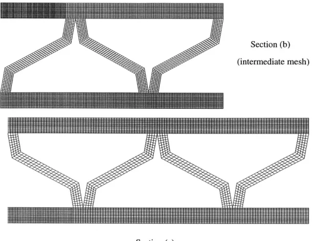
Two types of two-dimensional finite element models were generated for each projectile-target shield system. For the case with the monolithic and the double-layered shields, the target shields were modeled using four-node, axisymmetric elements with reduced integration (CAX4R), while for the case with BRAS shields, the model used is four-node, plain strain elements with reduced integration (CPS4R). Figures 2.4-2.6 show the finite element models for the double-layered shields with the plates spaced, the double-layered shields with different material combinations and the BRAS shields. For the double-layered shields with the plates spaced and that with the plates initially in contact, the impacted zone below the projectile was modeled by square elements with the size of 0.1 X 0.1mm, see Fig. 2.4. For the double-layered shields with different material combinations, the elements size varies from 0.2 X 0.2mm in the middle impact zone to 0.2 X 2mm near the out fringe, see Fig. 2.5. For the BRAS shields, the element size of the
impact zone is of 0.2 X 0.2mm, see Fig. 2.6. As indicated by the early study on mesh size effects, it was found that the numerical simulations based on such an element size agree well with experimental results [16].
For simplicity, the projectiles were considered as undeformable and were simply represented by rigid surfaces in our simulations. In reality, the projectiles would absorb
some kinetic energy and may break into pieces under shock wave loading, e.g. see Borvik et al. [17]. Therefore, assuming the projectile to be rigid would underestimate the ballistic limits of the shields.
Also, we have to correctly define the contact conditions between any two bodies because they may interact with each other. For the monolithic plates, the kinematic contact constraint was defined between the projectile and the impacted zone of the target shields. This problem becomes much more complex for the case with the double-layered shields and the BRAS shields. Obviously, the projectiles may sequentially get into contact with each layer and meanwhile the layers may interact with each other. Therefore, two types of contact constraints have to be defined. The kinematic contact
constraints were defined between the projectile and each layer, while the penalty contact constraint was defined between the layers. For all the possible contact interfaces, a constant frictional coefficient 0.1 was defined.
Fig. 2.4: The finite element model of a double-layered shield with the plates spaced impacted by a conical-nose projectile.
. . . .44 ... ......
Fig. 2.5: The finite element model of a double-layered shield with different material combinations impacted by a conical-nose projectile.
Section (a) Section (b) Section (c)
Section (a) (fine mesh)
Section (b) (intermediate mesh)
Section (c) (corse mesh)
Fig. 2.6: The finite element model of BRAS shield impacted by conical-nose projectile.
2.2
Plasticity and fracture models for tested materials
2.2.1 Weldox 460 E steel
For the double-layered shield with two plates spaced, the double-layered shield with two plates initially in contact and the BRAS shield, the target shields were assumed to be made of Weldox 460 E steel. As a class of rolled steels manufactured by SSAB, Sweden, Weldox steel is of high strength and of outstanding ductility. To study the mechanical properties of Weldox 460 E steel, a series of tensile tests were conducted by Borvik et al.
[18, 19]. In this thesis, the material constitute model proposed by Johnson and Cook [20] was used to describe the behaviors of Weldox 460 E steel under dynamic loading. The hardening rule including effects of the strain rates and temperature change is defined by
EO ~T -TO
where ff is the von Mises stress; E,> is the effective plastic strain; A, B, n, C, and m
are five material constants which need to be calibrated from tests; E,, and EO are the current and reference strain rate; Tn and To are the melting and room temperature; respectively. All the relevant material constants for Weldox 460 E steel are shown in Table 2.1. E (GPa) v p (kg/m3) FO (s-1) C 200 0.33 7850 5.OOx 10-4 0.0123 c, (J/kgK) Tm (K) To (K) m A (MPa) 452 1800 293 0.94 490 B (MPa) n D, D2 D3 383 0.45 0.0705 1.732 -0.54
To predict the material failure, a ductile fracture model was formulated by the equivalent plastic strain to fracture E, and the stress triaxiality ij, which is defined by the ratio of the mean stress a;m to the equivalent stress. The damage indicator D can be written as
D= _f -L dE (2)
0 E.I.(77)
A material point is considered to fail when D 1.0. The failed elements completely lose their load-carrying capability and are removed from the rest of the calculation. This fracture criterion was first suggested by Johnson and Cook [21] and was incorporated into our simulations. Also, Johnson and Cook suggested an exponential relationship between the effective plastic strain and the stress triaxiality:
f, = D, +D2exp (D3q) (3)
where DI, D2, and D3 denotes three material coefficients. Based on a series of tensile tests on round bars, Borvik et al. [18, 19] obtained test data for Weldox 460 E steel:
DI = 0.0705, D2 =1.732, and D3 = -0.54. Actually, Johnson-Cook fracture loci calibrated
from tensile tests were often extrapolated to the range of negative stress triaxialities in practical applications. Note that the ductility of materials under compression may be underestimated due to extrapolation. Here, the Johnson-Cook fracture locus was modified by introducing a cut-off value for the negative stress triaxiality at -1/3, see Fig. 2.7. The concept of the cut-off value was first introduced by Bao and Wierzbicki [22] to describe the sharp increase of the ductility of materials under compression. As demonstrated by Teng and Wierzbicki [11, 23], the cut-off value has a critical effect on the reconstruction of various fracture patterns in a number of high velocity impact problems.
5F
0 Test points S 4
Modified fracture locus with the cut-off value
Johnson-Cook fracture locus > 00 -1/3 -2 -1 0 1 Stress triaxiality
Fig. 2.7: Fracture loci for Weldox 460 E steel
2.2.2 Domex Protect 500 steel
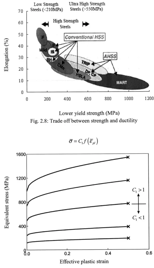
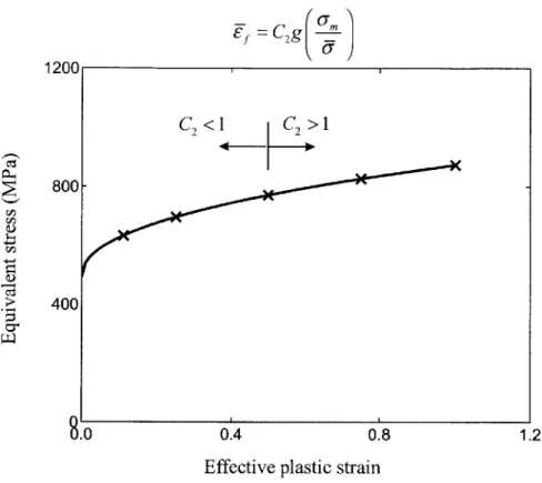
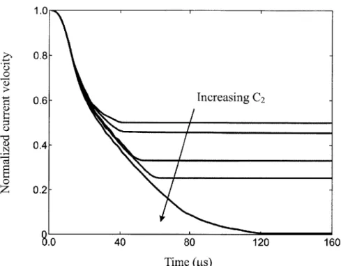
It is known that ductility and strength is two incompatible properties for traditional materials. High ductility always accompanies with low strength, and vice versa. It can be seen from Fig. 2.8, the trade off between strength and ductility of materials. Here two parameters, C1 and C2, are defined to facilitate our explanations. C, and C2 are the scaling
parameter of stress-strain curves and fracture strain respectively. Figure 2.9 shows the varies stress-strain curves with the same fracture strain, while Fig. 2.10 shows the same stress-strain curves with varies fracture strains. The meaning of C1 and C2 can be easily
understood from Fig. 2.9 and 2.10. Also, the trade off between strength and ductility can be rewrote using scaling parameter C1C2= const, see Fig. 2.11.
Low Strength
Steels (< 210MPa)
Ultra High Strength Steels (>'550NMPa) - Steel - Conventional H S$ -t 0 200 400 600 800 1000 1200 1600 800 400 f
Lower yield strength (MPa)
Fig. 2.8: Trade off between strength and ductility
6= C1f (P7) ... "o... KC, > 1 C, < I
c-0.2 0.4 0.6
Effective plastic strain
Fig. 2.9: Various stress-strain curves with the same fracture strain.
0 70 60 50 40 30 20 10 0 ri~ ri2 0.) I I I 1200|
&0
NJ
,C'g~j
0.4
Effective plastic strain
Fig. 2.10: The same stress-strain curves with various fracture strains.
4.01
C1C
Material in the lower Materi
1.0 2.0
2= const
layer
al in the upper layer
3.0 Scaling factor of flow stress, C1
Fig. 2.11: Relation between flow stresses and fracture strains C2<1 C>1 2 -1200 800 400 0.8 1.2 3.0 2.01 r0 I-0n 1.0 4.0 6.0
The perforation resistance of the monolithic plates varies with the stress-strain curve and fracture strain of materials. At first, the fracture strain is maintained to be the same, while the stress-strain curve is scaled with the base line stress-strain curve. Figure 2.12 shows the time history of the transient velocity of the projectile impacts at the target with materials of different stress-strain curve and the same fracture strain. Another condition is
scaling up the fracture strain and maintaining the stress-strain curve the same. Figure 2.13 shows the time history of the transient velocity of the projectile impacts at the target with materials of different yield strength and the same stress-strain curve. The plot of the normalized residual velocities of the projectile vs. the scaling parameters C, and C2 is shown in Fig. 2.14. 1.0 & 0.8-0.6 N 0.4-0.2- -Increasing C1 9.0 40 80 120 Time ([Ls)
Fig. 2.12: Time history of the transient velocity of the projectile impacts at the target with materials of different stress strain curve
0 * N 1.0 0.8 0.6 0.4 0.2 40 80 120 160 Time (ps)
Fig. 2.13: Time history of the transient velocity of the projectile impacts at the target with materials of different yield strength
,=C2 17-1. 0 0.8 0.6 0.4 0.2 0.5 1.0 C1 or C2 1.5
Fig. 2.14: Residual velocities vs. scaling parameters of yield strength and fracture strain Increasing
Variation of flow stresses
[ariation of fracture strain
-____________________________*
n
C2
60
In order to study the optimization effect of ductility and strength on perforation resistance, besides Weldox 460 E steel, another grade of metal of higher ductility and lower strength is used as the material for the double-layered shields. If the Weldox 460 E steel is considered as the base material, the modified material Domex Protect 500 steel can be introduced by scaling up twice the base line stress-strain curve and scaling down the base line fracture locus by half, i.e. C1 = 2, C2 = 0.5. Figure 2.15 shows the true
stress-strain curve of two types of armor steels studied in this thesis. In the following discussions, the high ductility material is represented by white box, while the low ductility material is represented by black box, see Fig. 2.15.
rJ~ H 2800 2400 2000 1600 1200 600 400 0 0 0.4 0.8 True strain 1.2 1.6
Fig. 2.15: The true stress-strain curve of two types of armor steels studied in this thesis Domex Protect 500
Weldox 460 E
-Chapter 3
Ballistic Resistance of the Double-layered
Shields with Two Plates Spaced and in
Contact
3.1 Heavy flat-nose projectile
In this section, the heavy flat-nose projectile is considered as the striker.
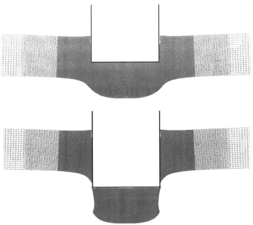
The first type of shield studied is the monolithic plate. Figure 3.1 shows a typical perforation process of the monolithic plate impacted by the heavy flat-nose projectile at VO = 285.4m/s. It can be observed that shear plugging is the predominant failure mode for
the monolithic target under normal impact by this projectile. The sharp corner of flat-nose projectile often induces crack formation and propagation through the shield thickness. Also, it was found that the target plate undergoes insignificant global deformation even at the impact velocity near the ballistic limit. The whole impacted zone beneath the
projectile is ejected as a plug. In order to verify the correctness of the numerical
simulation, some of the initial impact velocities in section 3 were selected to be identical to those in the impact test performed by Borvik et al. [12].
Fig. 3.1: The perforation process of the monolithic plate impacted by the heavy flat-nose
projectile at Vo = 285.4m/s.
The second type of shield considered is the double-layered shield with the plates in contact. Figure 3.2 shows the perforation process of the double-layered shield with the plates initially in contact impacted by the heavy flat-nose projectile at Vo = 285.4m/s.
Similar to the case of monolithic shied, the upper plate tends to fail by shear plugging and the plastic deformation is localized in the impacted zone. However, the failure mode of double-layered shield is different from that of monolithic plate. It is found that the deformation region of the lower plate extends well beyond the impacted zone. Also, thinning before fracture can be clearly observed in the lower plate. Another difference
from the monolithic plate is the pattern of crack formation and propagation. For the monolithic target, one single crack continuously grows through the whole thickness during the perforation process, while two separate cracks have to be formed for each part
in the double-layered shields. Generally speaking, crack initiation requires more energy dissipation than crack propagation.
I
I
Fig. 3.2: The perforation process of the double-layered shield with the plates initially in contact impacted by the heavy flat-nose projectile at Vo = 285.4m/s.
The third type of shield considered is the double-layered shield with the plates spaced. Figure 3.3 shows the perforation process of the double-layered shield with the plates spaced impacted by the heavy flat-nose projectile at Vo = 285.4m/s. In this case,
the upper plate suffers large bending deformation before contacting with the lower plate. It can be observed that the lower plate undergoes deep necking before failure. Tensile tearing is the dominating failure mode for both plates in this case.
Fig. 3.3: The perforation process of the double-layered shield with the plates spaced impacted by the heavy flat-nose projectile at Vo = 285.4m/s.
I
It can be concluded from the comparison that the transition of the failure mode from shear plugging in the monolithic plate to tensile tearing in the double-layered shield is accompanied with a considerable increase in plastic energy dissipation, particularly for the lower plate. In general, tensile tearing involves a larger deformed zone than shear plugging under the same impact condition. Figure 3.4 shows the time history of the plastic energy dissipation of the upper and lower plates among the three types of shields. The plastic energy absorbed by the lower plate of the double-layered shield with the plates spaced is almost twice as high as that absorbed by the corresponding part of the monolithic plate. 4 --- Lower plate -- Upper plate 3 Plates spaced Plates in contact Monolithic shield 0 0 50 100 150 200 Time (p.s)
Fig. 3.4: The time history of plastic energy dissipation of the three types of shields impacted by the heavy flat-nose projectile at Vo = 285.4m/s
(For the monolithic plate, the plastic energy for the upper and lower half was output separately.).
Apparently, large energy dissipation leads to low residual velocities of the projectile in the case with the double-layered shields. The residual velocity of the projectile vs. the initial impact velocity among all the three cases is plotted in Fig. 3.5. It can be observed
that, as the impact velocity approaches the ballistic limit, the double-layered shields become superior in resisting perforation over the monolithic plate. The ballistic limits of the three types of shields impacted by the heavy flat-nose projectile are given in Table 3.1. By replacing the monolithic plate with the double-layered shields of the same total thickness, the ballistic limit of the shield is improved by about 25.0%. This conclusion is confirmed by the impact tests conducted by Dey et al. [6]. According to test results, the double-layered shield was able to increase the ballistic resistance by about 30%. The present numerical prediction is also consistent qualitatively with Corran et al.'s test results [2] but contradicts to Radin and Goldsmith's test outcomes [3]. As Corran et al. [2] pointed out, the double-layered shield would become more effective than the
monolithic plate as the total thickness exceeded a critical value. Note, that the thickness of the shields studied by Radin and Goldsmith ranges from 1.6mm to 6.4mm, which is much smaller than the present case.
450 300 A 0 0 . 150 n Monolithic shield tes in contact tes spaced Pla Plal
Fig. 3.5: The initial
0 150 300 450
Initial impact velocity (mis)
impact velocity vs. the residual velocity for the three types of shields impacted by the heavy flat-nose projectile.
Monolithic plate Double-layered shield Double-layered shield with the plates in contact with the plates spaced 186.1 (1.00) 232.0 (1.25) 236.0 (1.27)
Table 3.1: The ballistic limits of the shields impacted by the heavy, flat-nose projectile (unit: m/s)
For the double-layered shields, it can also be concluded from Fig. 3.3 that an increase in the spacing between the two plates improves only the ballistic resistance. However, this conclusion is contrary to the test results obtained by Marom and Bodner [1]. As they point out, the beams in contact always have higher ballistic limits than the beams spaced. Note that in their study the beams were so widely separated that there was actually no interaction between two beams during the perforation process, while in the present case, the two plates in the double-layered shields strongly interact with one another. This contradiction indicates that there may exist an optimal spacing for the ballistic resistance of the double-layered shield.
3.2 Heavy conical-nose projectile
In the previous section, the surface contact between the projectile and the shield was assumed. Actually, it is more likely that the sharp corner of a projectile may first pierce a
shield. This type of perforation scenario is represented by introducing the heavy conical-nose projectile.
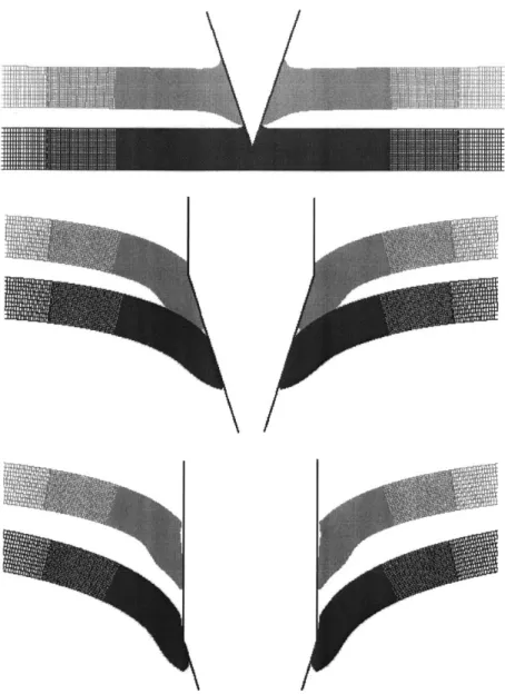
Figures 3.6-3.8 show the perforation processes of the three types of shields impacted normally by the conical-nose projectile. For the double-layered shield with the plates initially in contact, the lower plate experiences considerable bending deformation compared with the upper plate. The two plates, which are initially in contact, are
separated clearly during the perforation process. Among the three cases, the materials in the impacted zone are pushed aside as the projectile penetrates through the thickness. During the perforation process, no clear sign of crack formation and propagation is found. The failure mode for all three types of shields is a ductile hole enlargement, independent of the impact velocity. Therefore, the introduction of the double-layered shield does not induce the transition of the failure mode for the heavy conical-nose projectile. This is different from the preceding case with the heavy flat-nose projectile.
I I
I
Fig. 3.6: The perforation process of the monolithic plate impacted by the heavy conical-nose projectile at VO = 317.9m/s.
Fig. 3.7: The perforation process of the double-layered shield with the plates initially in contact impacted by the heavy conical-nose projectile at Vo = 317.9m/s.
Fig. 3.8: The perforation process of the double-layered shield with the plates spaced impacted by the heavy conical-nose projectile at Vo = 317.9m/s.
Figure 3.9 shows the plots of the initial impact velocity vs. the residual velocity for the three types of shields. Apparently, the predicted residual velocities for the
double-layered shields are always higher than those for the monolithic plate. Since neither large shear nor tensile stresses can be transferred between the two plates of the double-layered shield, its shear resistance is weakened. This should be the reason for the 8.0% decrease in the ballistic limits compared to the monolithic plate, see Table 3.2. This
conclusion agrees with the test results obtained by Radin and Goldsmith [3], Almohandes et al. [4], and Dey et al. [6].
600 U, U 0 U 400 F 200 I' 0 0 200 400
Initial impact velocity (mi/s)
600
Fig. 3.9: The initial impact velocity vs. the residual velocity for the three types of shields impacted by the heavy conical-nosed projectile
Monolithic plate Double-layered shield Double-layered shield with the plates in contact with the plates spaced
305.9 (1.000) 282.0 (0.992) 280.0 (0.915)
Table 3.2: The ballistic limits of the shields impacted by the heavy, conical-nose projectile (unit: m/s)
According to our simulation results, the predicted residual velocities for the double-layered shield with the plates in contact are a little higher than those with the plates spaced. However, the difference is so small that it is difficult to discern in Fig. 3.9. Again, the results here agree with the observations by Almohandes et al. [4] and Dey et
Monolithic shield Plates in contact Plates spaced
al. [6]. Therefore, it may be concluded that an increase in the spacing between the two plates would not considerably improve the ballistic resistance of double-layered shields.
3.3 Light flat-nose projectile
The projectile considered in this section is a flat-nose projectile of the mass Mo = lOg and the diameter d = 7.6mm. This striker is close in size to the smallest Fragment
Simulating Projectile (FSP) of 0.30" caliber specified in Military Standard
MIL-P-46593A [15]. Since the projectile is relatively light, a high initial impact velocity is required to completely perforate the shield. This leads to a different failure mode from shear plugging or tensile tearing.
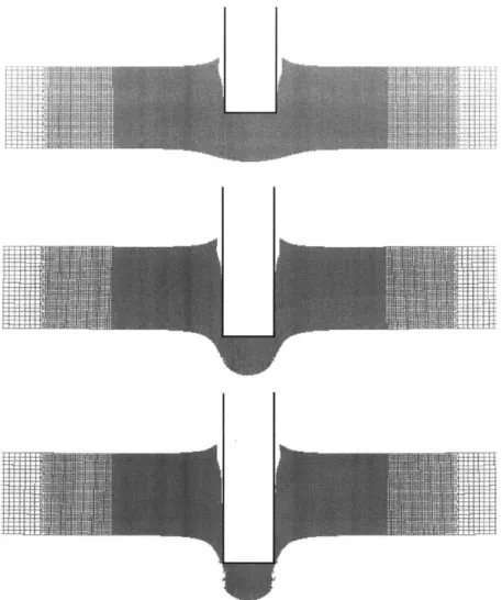
Figure 3.10 shows the perforation process of the monolithic plate at Vo = 600m/s. It can be observed that the materials in the impacted zone beneath the projectile are pushed aside and a cavity, whose diameter is larger than that of the projectile, is formed. In contrast, at a low initial impact velocity the cavity is of almost the same diameter through the target thickness, e.g. see Fig. 3.1. As the projectile approaches the bottom surface of the shield, shear plugging becomes the predominant failure mode and a plug of reduced thickness is ejected. Although the combined action of tension and shear is observed in the later process, ductile hole enlargement should be the dominating failure mode. Cavity formation contributes a large part of plastic energy dissipation. In contrast, in the case with the heavy flat-nose projectile, shear plugging is always observed in the monolithic plate and the ejected plug is of almost the same diameter as the original plate.
Fig. 3.10: The perforation process of the monolithic plate impacted by the light flat-nose
projectile at Vo = 600.0m/s.
Figure 3.11 shows the perforation process of the double-layered shield with the plates initially in contact impacted by the light flat-nose projectile at Vo = 600m/s. It can be observed that the dominating failure mode of the upper plate is ductile hole enlargement, this is similar to the monolithic plate. However, the lower plate experiences small
bending deformation and necking is observed clearly before fracture. Apparently, the failure mode of the case with the plates spaced is similar to that with the plates initially in contact, see Fig. 3.12.
Fig. 3.11: The perforation process of the double-layered shield with the plates initially in contact impacted by the light flat-nose projectile at Vo = 600.0m/s.
I
11
Fig. 3.12: The perforation process of the double-layered shield with the plates spaced impacted by the light flat-nose projectile at Vo = 600.0m/s.
Figure 3.13 shows the plots of the initial impact velocity vs. the residual velocity for the three types of shields. As the initial impact velocity approaches the ballistic limit, the advantage of the double-layered shields over the monolithic plate becomes smaller. According to our results, the ballistic limits of the double-layered shields are higher by
about 7.0% than that of the monolithic plate, see Table 3.3. The reason for increase in the ballistic limit of the double-layered shields should be attributed to the increase in the bending deformation of the lower plate. Of the same total thickness, the detail bending stiffness of the double-layered shield is only one quarter of that of the monolithic plate.
SoD A-A* 600 400 200 0 0 -N--Monolithic shield Plates in contact Plates spaced 200 400 600
Initial impact velocity (m/s)
900
Fig. 3.13: The initial impact velocity vs. the residual velocity for the three types of shields impacted by the light flat-nose projectile.
Monolithic plate Double-layered shield Double-layered shield with the plates in contact with the plates spaced
487.4 (1.00) 520.0 (1.07) 523.0 (1.07)
Table 3.3: The ballistic limits of the shields impacted by the light, flat-nose projectile (unit: m/s)
According to our results, the calculated ballistic limit of the double-layered shield with the plates spaced is slightly higher than that with the plates in contact. However, the variation in the spacing between the two plates is not able to considerably improve the ballistic resistance, because the failure mode is kept almost the same.
56
3.4 Light conical-nose projectile
The light conical-nose projectile of the mass 1 O.Og is considered as a simplification of a standard 7.62mm hard-core bullet. It is realized that a real bullet projectile is usually of the ogival-nose rather than the conical nose. However, Dey et al. [24] found from a series of tests that a conical-nose projectile has a very similar perforation capability to the ogival-nose one.
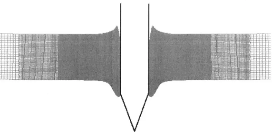
Figures 3.14-3.16 show the perforation processes of the three types of shields
impacted by the light conical-nose projectile at VO = 600.0m/s. It can be observed that all the three shields fail by ductile hole enlargement. The shields are subjected to little structural deformation and plastic deformation concentrates in the impacted zone beneath the projectile. According to our results, the failure mode keeps almost the same at a range of impact velocities. At the same time, this failure mechanism is almost identical to that of the previous case with the heavy projectile. Therefore, it can be concluded that, for the
conical-nose projectile, the double-layered shield would not introduce a new failure mode.
V
Fig. 3.14: The perforation process of the monolithic plate impacted by the light conical-nose projectile at Vo = 600.0m/s.
V
V
Fig. 3.15: The perforation process of the double-layered shield with the plates initially adjacent impacted by the light conical-nose projectile at Vo = 600.0m/s.
V
Fig. 3.16: The perforation process of the double-layered shield with the plates spaced impacted by the light conical-nose projectile at VO = 600.0m/s.
Figure 3.17 shows the plots of the initial impact velocity vs. the residual velocity for the three types of shields. The corresponding ballistic limits are listed in Table 3.4. It can be observed that the double-layered shield is slightly weaker in ballistic resistance. However, the difference between the effect of the monolithic plate and the
double-layered shields is so small that it can be neglected. At the same time, the
numerical results indicate that the increase in the spacing between the two plates does not improve the ballistic resistance of the shield.
800 U 0 600 400 200 0 0 200 400 600
Initial impact velocity (m/s)
goo
Fig. 3.17: The initial impact velocity vs. the residual velocity for the three types of shields impacted by the light conical-nose projectile.
Monolithic plate Double-layered shield Double-layered shield with the plates in contact with the plates spaced
525.9 (1.000) 524.5 (0.997) 522.5 (0.994)
Table 3.4: The ballistic limits of the shields impacted by the light, conical-nose projectile (unit: m/s)
A few armor piercing experiments has been performed on the double/multiple-layered shields impacted by the standard 7.62mm calibre bullet balls, e.g. Almohandes et al. [4], Gupta and Madhu [25]. According to their results, there is slight degradation in the ballistic resistance of the double/multiple-layered shields, compared to the monolithic plate of the same total weight. Those experimental results qualitatively agree with the present numerical prediction.
--- Monolithic shield Plates in contact Plates spaced
3.5
Comparison with experimental results
Besides numerical study, Borvik et al. [12, 13] also performed many experimental tests on the ballistic resistance of a Weldox 460 E steel shield under the impact of a flat-nose, a round-nose, and a conical-nose projectile. By conducting the tensile tests on round bars under various strain rates and temperature change [19], the strength and fracture properties of Weldox steels were calibrated. In this section, the experimental results published in the literature are used to verify the numerical procedures. The
geometrical dimensions of the projectile-target shield systems for the monolithic plates were taken to be identical to the one designed by Borvik et al. [12]. Therefore, the present numerical predictions can be directly verified by comparing to the experimental results.
The plots of the initial impact velocity vs. the residual velocity for the case with the monolithic plate under impact by the heavy flat-nose and conical-nose projectiles are shown in Fig. 3.18 and 3.19. It was observed that the numerical results agree well with the test results. Hence, the correctness of the present finite element procedure is
validated.
Recently, Dey et al. [6] performed 36 perforation tests on double-layered shields. In his experiments, the target shields made of Weldox 700 E steel were impacted by a flat-nose and a ogival-nose projectile at sub-ordnance velocities. According to his results, the ballistic resistance could be increased by about 30% by using the double-layered configuration instead of the monolithic plates in the case with the flat-nose projectile, see Fig. 3.20. This is in general in accordance with the present numerical results. However, the experimental data cannot be directly compared with the present numerical results, because the plasticity and fracture properties of Weldox 700 E steel is significantly different from those of Weldox 460 E steel, which is used in the present numerical simulations.
450 300 I. U4 0 150 U 0 150 300 450
Initial impact velocity (m/s)
Fig. 3.18: Comparison of the residual velocities between the numerical prediction and the experimental results for the monolithic plate impacted by the heavy flat-nose projectile.
600
400
0
200
0 200 400 600
Initial impact velocity (n/s)
Fig. 3.19: Comparison of the residual velocities between the numerical prediction and the experimental results for the monolithic plate impacted by the heavy conical-nose
projectile.
- Present numerical prediction p1 Experimental data
Present numerical prediction Experimental data
450 300 0 4)1~ 0 0 150 300 450
Initial impact velocity (in's)
Fig. 3.20: Comparison of experimentally obtained residual velocities between the monolithic and the double-layered shield.
IN . Monolithic shield Plates in contact
9 t E)