Publisher’s version / Version de l'éditeur:
Applied Optics, 47, 13, pp. C124-C130, 2008-05-01
READ THESE TERMS AND CONDITIONS CAREFULLY BEFORE USING THIS WEBSITE. https://nrc-publications.canada.ca/eng/copyright
Vous avez des questions? Nous pouvons vous aider. Pour communiquer directement avec un auteur, consultez la première page de la revue dans laquelle son article a été publié afin de trouver ses coordonnées. Si vous n’arrivez pas à les repérer, communiquez avec nous à PublicationsArchive-ArchivesPublications@nrc-cnrc.gc.ca.
Questions? Contact the NRC Publications Archive team at
PublicationsArchive-ArchivesPublications@nrc-cnrc.gc.ca. If you wish to email the authors directly, please see the first page of the publication for their contact information.
NRC Publications Archive
Archives des publications du CNRC
This publication could be one of several versions: author’s original, accepted manuscript or the publisher’s version. / La version de cette publication peut être l’une des suivantes : la version prépublication de l’auteur, la version acceptée du manuscrit ou la version de l’éditeur.
Access and use of this website and the material on it are subject to the Terms and Conditions set forth at
Estimation of the average residual reflectance of broadband
antireflection coatings
Tikhonravov, Alexander V.; Trubetskov, Michael K.; Amotchkina, Tatiana V.;
Dobrowolski, J. A.
https://publications-cnrc.canada.ca/fra/droits
L’accès à ce site Web et l’utilisation de son contenu sont assujettis aux conditions présentées dans le site LISEZ CES CONDITIONS ATTENTIVEMENT AVANT D’UTILISER CE SITE WEB.
NRC Publications Record / Notice d'Archives des publications de CNRC:
https://nrc-publications.canada.ca/eng/view/object/?id=49aab04c-51a4-4ea7-bf5c-767ceb63eec9 https://publications-cnrc.canada.ca/fra/voir/objet/?id=49aab04c-51a4-4ea7-bf5c-767ceb63eec9Estimation of the average residual reflectance of
broadband antireflection coatings
Alexander V. Tikhonravov,1,* Michael K. Trubetskov,1Tatiana V. Amotchkina,1 and
J. A. Dobrowolski2
1Research Computing Center, Moscow State University, Leninskie Gory, 119992 Moscow, Russia 2Institute for Microstructural Sciences, National Research Council of Canada, Ottawa, Ontario KlA OR6, Canada
*Corresponding author: tikh@srcc.msu.ru
Received 18 September 2007; revised 23 October 2007; accepted 24 October 2007; posted 24 October 2007 (Doc. ID 87616); published 29 November 2007
We deal with optimal two-material antireflection (AR) coatings for the visible and adjacent spectral regions. It has been shown before that, for a given set of input parameters (refractive indices of the substrate, ambient medium and high- and low-index coating materials, and for a given spectral width of the AR coating), such designs consist of one or more clusters of layers of approximately constant optical thickness and number of layers. We show that, through the analysis of many different optimal coatings, it is possible to derive two parameters for a simple empirical expression that relates the residual average reflectance in the AR region to the number of clusters. These parameters are given for all possible combinations of relative spectral bandwidth equal to 2, 3, and 4; low-index to ambient-medium index ratio equal to 1.38 and 1.45; and high-to-low index ratio equal to 1.4, 1.5, and 1.7. The agreement between the numerically and the empirically calculated values of residual average reflectance is excellent. From the information presented the optical thin-film designer can quickly calculate the required number of layers and the overall optical thickness of an AR coating having the desired achievable residual average reflectance. © 2008 Optical Society of America
OCIS codes: 310.1210, 310.6805.
1. Introduction
Antireflection (AR) coatings make up more than 50% of the total optical thin-film market [1]. It is not surprising, therefore, that a great number of publi-cations are devoted to this topic. The first book on thin-film optics, published in 1946 [2], was devoted almost entirely to AR coatings. There are at least several thousands of papers that deal with the de-sign, fabrication, and applications of various types of AR coating. Multiple references to the most essential publications in this area can be found in Refs. [3– 8]. During the past two decades researchers have fo-cused their efforts mainly around two-component AR coatings that consist of alternating layers of high-and low-index materials [3,7,8]. This was triggered by the tremendous progress in thin-film technology that
made possible the accurate production of two-component AR designs that consist of non-quarter-wave layer optical thicknesses. Currently quite complicated AR coatings of this type with several dozens of layers can be successfully manufactured [7]. The thin-film maximum principle [9] shows that, at normal angle of incidence, two-component AR de-signs with the highest and lowest available refractive indices form an optimal class of AR designs. This result has also been confirmed numerically [10]. However, it should be mentioned that, for an oblique angle of incidence, especially for AR coatings operat-ing over wide angular ranges, other types of design might be preferable [4 – 6].
The ability to predict the achievable residual re-flectance level in AR coatings designed to operate in given spectral bands would be a great asset to thin-film designers. This average residual reflectance de-pends on many design parameters. It is known from thin-film theory (Ref. [14], pages 17–20) that spectral
0003-6935/08/130C124-7$15.00/0 © 2008 Optical Society of America
properties of any coating depend on the ratios of re-fractive indices of all the layer materials and sur-rounding media. For two-component designs we should consider the ratio of high and low refractive indices, the ratio of substrate and ambient medium refractive indices, and the ratio of low refractive in-dex and ambient medium refractive inin-dex. For all the coatings, in particular for AR coatings, the design total optical thickness is an extremely important design parameter [15,16]. The computational exper-iments of many authors [3,17,18] show that the av-erage residual reflectance depends strongly on the width of the AR spectral region. It is evident that it is extremely difficult to obtain an analytical expression for the average residual reflectance because so many essential parameters are involved and because their dependencies are interconnected.
An attempt to predict the achievable performance of broadband AR coatings that was based on numer-ical and statistnumer-ical analyses was presented in Ref. [17], in which an empirical formula predicting the average residual reflectance of broadband AR coat-ings depending on the most essential parameters was given. According to this formula the average value of residual reflectance tends to zero with a growing total optical thickness of AR designs. Another version of such a formula is presented in Ref. [19].
Here we attempt to obtain a formula for estimation of the achievable average residual reflectance of broadband AR coatings. Because it is difficult to ob-tain such a formula entirely on the basis of rigorous theoretical considerations, we use an empirical ap-proach based on well-established specific properties of AR designs and also exploit some of our previous theoretical results. It is well known that spectral re-flectance curves of optimal AR designs exhibit specific Chebyshev-like oscillations around average residual reflectance levels [3,17,18]. With a growing design total optical thickness, specific layer clusters are formed in optimal AR designs [18]. Designs with a large number of layers have quasi-periodic groups of layer clusters whose origin was theoretically ex-plained with the help of the Fourier-transform theory [18]. In Section 2 we consider and compare the results of multiple computational experiments for designing AR coatings with various spectral widths and various input design parameters. These results obviously demonstrate cluster structures in optimal AR designs and empirically indicate the existence of limits on average residual reflectances of AR designs for all the combinations of design parameters considered.
In Section 3 we propose a simple two-parameter formula that expresses with high accuracy the aver-age residual reflectance of optimal AR designs as a function of the number of clusters. Our previous the-oretical results enable us to relate the number of clusters to the total optical thickness of a design and to other design parameters. From this formula we can derive an expression that permits one to estimate the relative decrease in the residual AR design re-flectance resulting from a further elaboration of the design structure. We believe that these expressions
and the two-dimensional plots for the lowest possible average residual reflectances presented in Section 3 will be useful for the design and manufacture of prac-tical broadband AR coatings. Final conclusions are presented in Section 4.
2. Numerical Study of Sequences of Optimal Antireflection Designs
As mentioned above, we consider single band normal incidence two-material AR coatings. Throughout this paper, the ambient medium is assumed to be air with
na⫽ 1 and the substrate is assumed to be glass with
ns ⫽ 1.52. Refractive indices of low- and high-index
materials nL and nH can have different values that
are specified later. The lower and upper limits of the AR spectral region are denoted by land u,
respec-tively.
It was shown in Ref. [11] that the optimization of AR designs with respect to the thicknesses of design layers is an optimization problem that is close to the optimization of convex functions. This is an impor-tant fact because any convex function has a single minimum that can be reliably found using various optimization methods. Thus, from a computational point of view, designing AR coatings is usually sim-pler than the design of optical coatings of other types. In our computational experiments we applied mod-ern versions of the needle optimization technique [13] that enable one to obtain not a single AR design but a series of optimal AR designs with various combina-tions of design total optical thicknesses and numbers of layers. These two design parameters are denoted below as TOT and N, respectively.
Modern design software makes possible the gener-ation of a whole series of AR designs with different
TOT and N values in a short period of time. Because
of this fact we were able to perform a numerical in-vestigation of multiple AR designs with various com-binations of refractive indices nHand nLand various
widths of AR spectral bands. From a theoretical point of view, ratios of refractive indices are more impor-tant than their absolute values [14]. In what follows we therefore choose to work with the ratios of high and low refractive indices HL⫽ nH兾nL and low and
ambient medium refractive indices La⫽ nL兾na. Along
with the above parameters, each AR design is also characterized by its average residual reflectance Rav,
which is defined by the equation
Rav⫽ 1 u⫺ l
冕
l u R()d, (1)where R共兲 is the reflectance of the design. The main goal of our computational experiments was to study the dependence of the average residual reflectance values Ravon the design total optical thickness TOT
and other design parameters. To achieve this goal we constructed several hundred AR designs with
differ-ent combinations of design parameters. It is obvi-ously impossible to present detailed information about all these designs here, but luckily the presen-tation of all the results is not necessary because there are some basic structural properties that are typical for all sets of optimal AR coatings with fixed HL, La
and u兾lvalues. These structural properties are
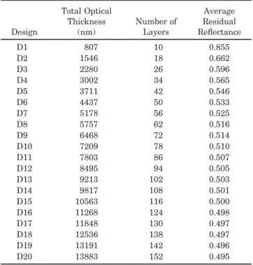
pre-sented in detail for one set of optimal AR designs. Table 1 presents the characteristics of twenty AR designs with various TOT values obtained for refrac-tive indices nH⫽ 2.35, nL ⫽ 1.45 and for the 400 –
1200 nm AR wavelength region. The design total optical thicknesses TOT, number of layers, and the average values of the residual reflectances Rav are
listed in columns 2– 4. As one would expect, Rav
val-ues decrease with an increase in design total optical thicknesses. The dependence of Rav on the design
parameters will be discussed later in more detail. It is necessary to stress that, for any combination of refractive indices and AR spectral bandwidths, a set of optimal AR designs is always arranged in such a way that total optical thicknesses and number of lay-ers of optimal designs are increased monotonically by nearly equal increments. This property is clearly seen in Table 1. It was discussed in detail in our previous paper [3], where the quantization of optimal AR de-signs was explained by the formation of special clus-ters of layers in optimal designs.
According to the third column of Table 1, the num-ber of layers of AR designs usually increases by eight from one optimal design to the next, because, for this particular AR problem, layer clusters are formed that consist of eight layers. The formation of new layer clusters is illustrated in Fig. 1, where the refractive-index profiles of the first five designs from Table 1
are shown. The refractive-index profiles of designs D1–D4 are presented in Fig. 1 in a discontinuous form to illustrate clearly the formation of layer clus-ters. One can see that there are groups of four layers at the substrate side and groups of six layers at the ambient medium side that were formed in the D1 design and then are repeated from one design to an-other with only small variations. Eight-layer clusters with nearly the same layers are formed inside the designs between these two groups of initial and final layers. The D2 design has one such cluster, D3 has two clusters, and so on.
In Ref. [3] the following equation for estimating the optical thickness Tcof layer clusters was obtained:
Tc⫽ u 2
冋
1 ⫹ 2 arcsin冉
HL⫺ 1 HL⫹ 1冊册
. (2)Note that uhere is the upper wavelength boundary
of the AR spectral band and HLis the ratio of the high
and low refractive indices. For our current values of these parameters, Eq. (2) results in a value for Tcthat
is equal to 691 nm, which is in excellent agreement with the average increment of 688 nm in the optical thicknesses of AR designs in the second column of Table 1.
Reflectances of the D1–D5 designs are shown in Fig. 2 by use of wavenumber spectral units. In Fig. 2 the wavenumber is defined by the expression 2兾, where is the wavelength of the incident light in vacuum. The spectral region from 400 to 1200 nm thus corresponds to from 52360 to 157080 cm⫺1 in the wavenumber scale. One can see that the spectral reflectance curves have specific oscillations inside the AR spectral band. The origin of these oscillations is explained in Ref. [20] on the basis of the general analytical properties of the spectral characteristics of optical coatings [21]. Because this topic has no direct bearing on the main goal of our paper, we do not discuss it here and refer the interested reader to Ref. [20]. In all other computational experiments with AR coatings analogous structural properties and cluster
Table 1. Parameters of the AR Designs for the 400 –1200 nm Spectral Region Design Total Optical Thickness (nm) Number of Layers Average Residual Reflectance D1 807 10 0.855 D2 1546 18 0.662 D3 2280 26 0.596 D4 3002 34 0.565 D5 3711 42 0.546 D6 4437 50 0.533 D7 5178 56 0.525 D8 5757 62 0.516 D9 6468 72 0.514 D10 7209 78 0.510 D11 7803 86 0.507 D12 8495 94 0.505 D13 9213 102 0.503 D14 9817 108 0.501 D15 10563 116 0.500 D16 11268 124 0.498 D17 11848 130 0.497 D18 12536 138 0.497 D19 13191 142 0.496 D20 13883 152 0.495
Fig. 1. Refractive-index profiles of the first five designs from Table 1 .
formations were observed. For each combination of refractive indices and AR spectral bandwidths we designed sets of AR coatings with as many as several hundred layers. In Table 2 we present only the inte-grated results of our computational experiments.
In the fourth and fifth columns of Table 2 we com-pare the theoretical and the experimental optical thicknesses of the layer clusters. Good agreement between these values is always observed. The num-ber of layers in the cluster is listed in the sixth col-umn of Table 2. One can see that the cluster thicknesses and the number of layers within them in general increase with an increase of the relative width of the AR spectral band. It is also seen from Table 2 that optical thicknesses of layer clusters are mainly dependent on the width of the AR spectral band and are much less dependent on the refractive indices.
Because the cluster structure is a basic property of optimal AR designs, it is reasonable to depict the dependence of Rav not on design total optical
thick-ness or on the number of layers in a design, but on the number of clusters in a design. In Figs. 3–5 we present the experimental dependence of Rav on the
number of design clusters for different AR spectral bands. Different markers are used to plot the results for different combinations of refractive indices. All the experimental data presented in Figs. 3–5 suggest that there are lower limits for the average residual reflectances Rav. These limits, of course, depend on
the refractive indices used in the AR designs as well as on the width of the AR spectral band.
Fig. 2. Reflectances of the first five designs from Table 1.
Table 2. Integrated Results for a Series of Optimal AR Designs for Different Combinations of Refractive Indices and AR Spectral Bandwidths
Spectral Range (nm) u兾l Refractive Indices nH, nL Optical Thickness of Clusters, Obtained Experimentally (nm) Optical Thickness of Clusters Predicted by the Theory (nm) Number of Layers in One Cluster 400–600 1.5 1.45, 2.35 372 346 4 400–700 1.75 1.45, 2.35 420 403 4 400–800 2.0 1.45, 2.03 465 443 6 400–800 2.0 1.45, 2.175 452 451 6 400–800 2.0 1.45, 2.466 478 467 6 400–800 2.0 1.38, 2.346 459 467 6 400–900 2.25 1.45, 2.35 520 518 6 400–1000 2.5 1.45, 2.35 590 576 6 400–1100 2.75 1.45, 2.35 640 642 8 400–1200 3.0 1.45, 2.03 687 664 8 400–1200 3.0 1.45, 2.175 698 677 8 400–1200 3.0 1.45, 2.465 709 700 8 400–1200 3.0 1.38, 2.346 720 700 8 400–1500 3.75 1.45, 2.35 900 864 10 400–1600 4.0 1.45, 2.03 919 885 10 400–1600 4.0 1.45, 2.175 930 903 10 400–1600 4.0 1.45, 2.465 955 934 10 400–1600 4.0 1.38, 2.346 949 934 10
Fig. 3. Average residual reflectances Ravof AR coatings designed for the AR spectral band from 400 to 800 nm with different refractive-index ratios: HL ⫽ 1.4, La ⫽ 1.45 (circles), HL ⫽ 1.5, La ⫽ 1.45 (triangles), HL ⫽ 1.7, La ⫽ 1.45 (squares), HL⫽ 1.7, La⫽ 1.38 (diamonds). The solid curves, calculated from Eq. (3), are in excellent agreement with the experimental data.
3. Empirical Equation for the Average Residual Reflectance of AR Designs
The results in Section 2 show that it is reasonable to relate the average residual reflectances of AR designs to the number of design clusters M. To approximate the experimentally obtained dependence of the aver-age residual reflectance Ravon the number of clusters
M we use the following two-parameter equation:
Rav⫽ R⬁b
1兾M. (3)
The parameter R⬁ represents the minimum achiev-able average residual reflectance for a given set of input design parameters. Both R⬁ and b depend on the refractive-index values as well as on the width of the AR spectral band. The parameters R⬁and b can be found by the least-squares method and are given in Table 3 for the twelve sets of input parameters corresponding to Figs. 3–5. Analytical dependencies
presented by Eq. (3) with continuous M values are represented by the solid curves in Figs. 3–5. Clearly there is excellent agreement between the experimen-tal Ravvalues and the values obtained from the
em-pirical Eq. (3).
Parameters R⬁ and b depend on the ratios of re-fractive indices HLand Laas well as on the ratio of
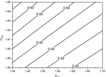
the boundary wavelengths of the AR spectral band. Table 3 shows that, for u兾l equal to 3 and 4, R⬁ exhibits a stronger dependence on these input pa-rameters than on b. We performed a great number of additional computational experiments to obtain more detailed information about the dependence of R⬁on the input design parameters. Results of these exper-iments are summarized in Figs. 6– 8 in which we present R⬁ values for the three ratios of boundary wavelengths of the AR spectral bands and for the different refractive index ratios HLand La. For the
sake of convenience R⬁values are presented as level curves. Equation (3) can be used to derive an expres-sion for the gain in optical performance when another
Fig. 4. Average reflectances Ravof AR coatings designed for the AR spectral band from 400 to 1200 nm with different refractive-index ratios: HL ⫽ 1.4, La ⫽ 1.45 (circles), HL ⫽ 1.5, La ⫽ 1.45 (triangles), HL⫽ 1.7, La ⫽ 1.45 (squares), HL⫽ 1.7, La ⫽ 1.38 (diamonds). The solid curves, calculated from Eq. (3), are in excellent agreement with the experimental data.
Fig. 5. Average values of residual reflectances Ravof AR coatings designed for the AR spectral band from 400 to 1600 nm with different refractive-index ratios: HL⫽ 1.4, La⫽ 1.45 (circles), HL⫽ 1.5, La⫽ 1.45 (triangles), HL⫽ 1.7, La⫽ 1.45 (squares), HL⫽ 1.7, La⫽ 1.38 (diamonds). The solid curves, calculated from Eq. (3), are in excellent agreement with the experimental data.
Table 3. Parameters R⬁and b Found by the Least-Squares Method for
the Twelve Sets of RavValues Presented in Figs. 3–5
u兾l HL La R⬁ b ln b 2 1.4 1.45 0.195 3.604 1.28 2 1.5 1.45 0.145 3.720 1.31 2 1.7 1.45 0.058 6.042 1.80 2 1.7 1.38 0.025 10.659 2.37 3 1.4 1.45 0.691 1.822 0.60 3 1.5 1.45 0.575 1.862 0.62 3 1.7 1.45 0.430 1.985 0.69 3 1.7 1.38 0.259 2.219 0.80 4 1.4 1.45 1.154 1.356 0.30 4 1.5 1.45 1.011 1.375 0.32 4 1.7 1.45 0.813 1.441 0.37 4 1.7 1.38 0.522 1.562 0.45
Fig. 6. Minimum achievable values of the average residual re-flectance Rav for the relative widths of the AR spectral band u兾l⫽ 2 and for different refractive-index ratios HLand La.
cluster is added to a particular AR coating design:
⌬Rav⬇ R⬁· ln b
M2. (4)
The sixth column of Table 3 presents ln b values for several sets of input parameters. One can see that only for u兾l⫽ 2 do these values exceed 1. To
illus-trate an application of Eq. (4), let us replace ln b in Eq. (4) by 1. Consider the relative decrease of the residual reflectance when the number of clusters in the AR design is increased from 3 to 4. With M ⫽ 3, Eq. (4) estimates this decrease to be 11% of the pre-vious value. If M ⫽ 5 the further addition of a cluster to the AR design will result only in a 4% reduction in the residual reflectance. It will be up to the optical coating engineer to decide whether such an increase in the complexity of the design structure is warranted by such a small improvement in the performance of the AR coating.
4. Conclusions
The empirical Eqs. (2)–(4), the data in Tables 2 and 3, and the data contained in Figs. 3– 8 provide the thin-film designer with all the information required to assist him in the design of wideband antireflection coatings for the visible and adjacent spectral regions. To design an AR coating for glass with a refractive index of 1.52 immersed in air, with a spectral width of u兾l⫽ 2, 3, or 4; with La⫽ 1.38 or 1.45; and with
HL⫽ 1.4, 1.5, or 1.7, it is sufficient to look up the
number of clusters required to achieve the desired residual reflectance in Figs. 3–5, and the optical thickness and number of layers in the cluster from Table 2. From this it is a simple matter to calculate the approximate overall thickness and the number of layers required in the AR coating. With this informa-tion one can obtain a satisfactory soluinforma-tion with most commercial thin-film design programs using materi-als that take into account the dispersion of the optical constants. For other values of Laand HL, the
param-eter R⬁ can be estimated from Figs. 6 – 8 and the value of parameter b interpolated from the values listed in Table 3. The residual reflectance in the AR region can then be evaluated with the aid of Eq. (3) for a reasonable value of the number of clusters M. Equation (4) serves to investigate the effect on Ravof
adding additional clusters. The optical thickness of the clusters can be obtained from Eq. (2). For other widths u兾l of the AR spectral region, interpolated
values of R⬁and b should also serve as a good starting point for numerical calculations.
It should be noted that refractive indices of coating materials exhibit a significant dispersion in wide spectral regions. In many publications on AR coat-ings nondispersive material indices are used and we also follow this tradition. Most of the calculations were performed with a low refractive index that was equal to 1.45. This refractive index was chosen be-cause most optical coating engineers use silica as the low-index material. In this research the wide spectral regions usually extended into the IR part of the spec-trum and a refractive index of 1.45 was deemed to be a reasonable average value for the refractive index of silica for such a broad spectral region. It is obvious that the same approach could be used to produce corresponding information for the design of wideband AR coatings in the infrared spectral region for semi-conducting substrate materials. A shortened version of this paper was first presented at the 2007 Optical Interference Coatings Topical Meeting [18].
This research is supported by the Russian Fund for Basic Research, project 07-07-00140-a.
References
1. N. Kaiser, “Optical coatings road-map,” presented at the In-ternational Workshop on Optical Coatings, Ottawa, Canada, 11 May 2006.
2. I. V. Grebenshchikov, L. G. Vlasov, B. S. Neporent, and N. V. Suikovskaya, Antireflection Coating of Optical Surfaces (State Publishers of Technical and Theoretical Literature, 1946) (in Russian).
3. J. A. Dobrowolski, A. V. Tikhonravov, M. K. Trubetskov, B. T. Fig. 7. Minimum achievable values of the average residual
re-flectance Rav for the relative widths of the AR spectral band u兾l⫽ 3 and for different refractive-index ratios HLand La.
Fig. 8. Minimum achievable values of the average residual re-flectance Rav for the relative widths of the AR spectral band u兾l⫽ 4 and for different refractive-index ratios HLand La.
Sullivan, and P. G. Verly, “Optimal single-band normal-incidence antireflection coatings,” Appl. Opt. 35, 644 – 658 (1996).
4. J. A. Dobrowolski, D. Poitras, P. Ma, H. Vakil, and M. Acree, “Toward perfect antireflection coatings: numerical investiga-tion,” Appl. Opt. 41, 3075–3083 (2002).
5. D. Poitras and J. A. Dobrowolski, “Toward perfect antireflec-tion coatings. 2. Theory,” Appl. Opt. 43, 1286 –1295 (2004). 6. J. A. Dobrowolski, Y. Guo, T. Tiwald, P. Ma, and D. Poitras,
“Toward perfect antireflection coatings. 3. Experimental re-sults obtained with the use of Reststrahlen materials,” Appl. Opt. 45, 1555–1562 (2006).
7. U. B. Schulz, U. B. Schallenberg, and N. Kaiser, “Symmetrical periods in antireflective coatings for plastic optics,” Appl. Opt. 42,1346 –1351 (2003).
8. U. B. Schallenberg, “Antireflection design concepts with equiv-alent layers,” Appl. Opt. 45, 1507–1514 (2006).
9. A. V. Tikhonravov, “Some theoretical aspects of thin film optics and their applications,” Appl. Opt. 32, 5417–5426 (1993). 10. P. G. Verly, J. A. Dobrowolski, and R. R. Willey,
“Fourier-transform method for the design of wideband antireflection coatings,” Appl. Opt. 31, 3836 –3846 (1992).
11. A. V. Tikhonravov and J. A. Dobrowolski, “Quasi-optimal syn-thesis for antireflection coatings: a new method,” Appl. Opt. 32,4265– 4275 (1993).
12. A. V. Tikhonravov, M. K. Trubetskov, and G. W. DeBell,
“Application of the needle optimization technique to the de-sign of optical coatings,” Appl. Opt. 35, 5493–5508 (1996). 13. A. V. Tikhonravov, M. K. Trubetskov, and G. W. DeBell,
“Optical coating design approaches based on the needle op-timization technique,” Appl. Opt. 46, 704 –710 (2007). 14. A. Thelen, Design of Optical Interference Coatings
(McGraw-Hill, 1988).
15. J. A. Dobrowolski, “Comparison of the Fourier transform and flip-flop thin-film synthesis methods,” Appl. Opt. 25, 1966 – 1972 (1986).
16. A. V. Tikhonravov, M. K. Trubetskov, T. V. Amotchkina, and M. A. Kokarev, “Key role of the coating total optical thickness in solving design problems,” Proc. SPIE 5250, 312–321 (2004). 17. R. Willey, “Predicting achievable design performance of broad-band antireflection coatings,” Appl. Opt. 32, 5447–5451 (1993). 18. A. V. Tikhonravov, M. K. Trubetskov, T. V. Amotchkina, and S. A. Yanshin, “Structural properties of antireflection coat-ings,” in Proceedings of Optical Interference Coatings on
CD-ROM, presentation WB5 (Optical Society of America, 2007).
19. R. Willey, “Refined criteria for estimating limits of broad-band AR coatings,” Proc. SPIE 5250, 393–399 (2004).
20. T. V. Amotchkina, “Analytical properties of spectral charac-teristics of antireflection optical coatings,” Vestnik MGU Ser. 3 Fiz. Astron. (posted 16 July 2007, in press).
21. A. V. Tikhonravov, P. W. Baumeister, and K. V. Popov, “Phase properties of multilayers,” Appl. Opt. 36, 4382– 4392 (1997).