HAL Id: hal-02505157
https://hal.sorbonne-universite.fr/hal-02505157
Submitted on 11 Mar 2020
HAL is a multi-disciplinary open access
archive for the deposit and dissemination of
sci-entific research documents, whether they are
pub-lished or not. The documents may come from
teaching and research institutions in France or
abroad, or from public or private research centers.
L’archive ouverte pluridisciplinaire HAL, est
destinée au dépôt et à la diffusion de documents
scientifiques de niveau recherche, publiés ou non,
émanant des établissements d’enseignement et de
recherche français ou étrangers, des laboratoires
publics ou privés.
Astronomy Astrophysics Multiple black hole system in
4C31.61 (2201+315)
J. Roland, C. Gattano, S. Lambert, F. Taris
To cite this version:
J. Roland, C. Gattano, S. Lambert, F. Taris. Astronomy Astrophysics Multiple black hole system
in 4C31.61 (2201+315). Astronomy and Astrophysics - A&A, EDP Sciences, 2020, 634, pp.A101.
�10.1051/0004-6361/201834740�. �hal-02505157�
https://doi.org/10.1051/0004-6361/201834740 c J. Roland et al. 2020
Astronomy
&
Astrophysics
Multiple black hole system in 4C31.61 (2201+315)
J. Roland
1, C. Gattano
2, S. B. Lambert
3, and F. Taris
31 Institut d’Astrophysique, UPMC Univ. Paris 06, CNRS, UMR 7095, 98 bis Bd Arago, 75014 Paris, France e-mail: roland@iap.fr
2 Laboratoire d’Astrophysique de Bordeaux, Univ. Bordeaux, CNRS, B18N, Allée Geoffroy Saint-Hilaire, 33615 Pessac, France 3 SYRTE, Observatoire de Paris, Université PSL, CNRS, Sorbonne Université, LNE, France
Received 29 November 2018/ Accepted 11 December 2019
ABSTRACT
Modeling trajectories of radio components ejected by the nucleus of 4C31.61 (2201+315) and observed by very long baseline inter-ferometry (VLBI) in the frame of the MOJAVE survey suggests that they are ejected from three different origins that possibly host three different supermassive black holes. These origins correspond to three stationary components, one of which one is the VLBI core. Most of the mass of the nucleus is associated with a supermassive binary black hole system whose separation is ≈0.3 milliarc second, that is, a distance of ≈1.3 parsec and the mass ratio is ≈2. In contrast, the mass ratio with respect to the third black hole is ≈1/100. The three origins lie within 0.6 milliarc second, or a distance of ≈2.6 parsec. Based in this structure of the nucleus, we explain the variations observed in the astrometric coordinate time series obtained from VLBI geodetic surveys. This study shows that it is possible to exploit large MOJAVE-like VLBI databases to propose more insights into the structure of the extragalactic radio sources that are targeted by VLBI in geodetic and astrometry programs.
Key words. astrometry – galaxies: jets – galaxies: individual: 2201+315
1. Introduction
Very long baseline interferometry (VLBI) observations of nuclei of extra galactic radio sources show that the ejection of VLBI components does not follow a straight line, but wiggles. These observations suggest a precession of the accretion disk that can be explained if the nuclei contain either a spinning single black hole (BH) or a binary black hole (BBH) system. We developed a minimization method by first modeling the ejection of a VLBI component by a spinning single BH, which produces the preces-sion of the accretion disk. Then we modeled the ejection of a VLBI component by a BBH system, taking the precession of the accretion disk and the motion of the BHs into account.
The method has been applied to 0420-014 (Britzen et al.
2001), 3C 345 (Lobanov & Roland 2005), 1803+784 (Roland
et al. 2008), 1823+568 and 3C 279 (Roland et al. 2013), and
1928+738 (Roland et al. 2015). Modeling VLBI ejections
pro-duces evidence that nuclei of extragalactic radio sources con-tain BBH systems. These systems can form when galaxies merge (Begelman et al. 1980), andBritzen et al.(2001) suggested that if nuclei of extragalactic radio sources contain BBH systems, the association of extragalactic radio sources with elliptical galax-ies can be explained. It also explains why quasars (quasi-stellar radio sources) represent about 5% of the quasi-stellar objects (QSO). For reviews for the formation of BBH systems in galaxy mergers, seeColpi & Dotti(2011),Colpi(2014), andVolonteri et al.(2016).
When a nucleus contains a BBH system, the two BHs can eject VLBI components, and both can be detected using VLBI observations. In this case, we observe the core and one station-ary component, and we observe two families of trajectories. This
is, for instance, the case for 3C 279 (Roland et al. 2013) and
1928+738 (Roland et al. 2015). However, it is not always the
case, and in some cases, only one BH can be detected using VLBI observations, the other being “inactive”.
In this article, we use for the Hubble constant Ho ≈
73 km s−1Mpc−1and D
L ≈ 1460 Mpc for the luminosity distance
of 2201+315 and model the ejection of the VLBI components
of 4C31.61 ≡ 2201+315 using data from the Monitoring Of Jets
in Active galactic nuclei with VLBA Experiments (MOJAVE),
that is, the 15 GHz observations and the definitions of the di
ffer-ent componffer-ents of Table 3 ofLister et al.(2019). The analysis
of MOJAVE data with our minimization method suggests that
the nucleus of 2201+315 contains three BHs associated with the
stationary components C0 (the core), C3, and C9 (see Fig.1).
Most of the mass of the nucleus is associated with the BBH sys-tem C0–C9, whose separation is RC0−C9= 0.296+0.066−0.020mas,
cor-responding to a projected linear distance= 1.3+0.26−0.09pc, and the
mass ratio is MC9/MCO = 2 ± 0.5. The mass of the third BH
is MC3/(MC0 + MC9) ≈ 1/100. The distance between C0 and
C3 is RC0−C3 = 0.557+0.124−0.124mas, which translates into ≈2.4 pc.
Calling G, the center of gravity of the system C0–C9, the dis-tance between component C3 and the center of gravity G is RG−C3= 0.369+0.124−0.124mas, that is, ≈1.6 pc (see Table1).
We show that component C6 is ejected from the core C0, component C7 is ejected from the stationary component C3, and component C13 is ejected from the stationary component C9. We deduce the characteristics of the BBH system constituted by the core C0 and the stationary component C9. We also deduce the characteristics of the third BH that is associated with the station-ary component C3. Finally, knowing the structure of the nucleus
of 2201+315, we discuss the influence of the variations in the
ratio of the flux densities of the three BHs and of the ejection of a new VLBI component on the coordinate time series obtained
by the analysis of geodetic VLBI observations (Gattano et al.
2018).
Open Access article,published by EDP Sciences, under the terms of the Creative Commons Attribution License (https://creativecommons.org/licenses/by/4.0),
Table 1. Distances between the different BH. System Separation C0–C9 RC0−C9= 0.296+0.066−0.020mas ≈1.3 pc C0–C3 RC0−C3= 0.577+0.124−0.124mas ≈2.4 pc West (mas) -0.5 -0.4 -0.3 -0.2 -0.1 0.0 0.1 North (mas) -0.6 -0.5 -0.4 -0.3 -0.2 -0.1 0.0 0.1 Core - C0 (M = 1) C3 ( M = 0.03) C9 (M = 2) G (center of gravity) L1 (Lagrange point)
Fig. 1.Structure of the nucleus of 2201+315. The analysis of MOJAVE
data with our minimization method suggests that the nucleus of 2201+315 contains three BHs. G is the center of gravity of the BBH system C0–C9 and L1 is the first Lagrange point of the BBH system C0–C9; this is the point where the gravitational forces of the BHs C0 and C9 are equal. In order to obtain a stable solution, the radii of the accretion disks around C0 and C9 have to be smaller than the distances L1–C0 and L1–C9, respectively.
2. Methods and data
2.1. Properties of the BBH system solution
To model the ejection of a VLBI component, we assumed that the VLBI component corresponds to the relativistic ejection of
an electron–positron (e−e+) plasma referred to as the beam. It
is surrounded by a subrelativistic electron–proton (e−p) plasma
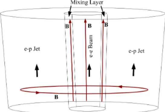
called the jet. The relativistic beam is responsible for the for-mation of VLBI components, their synchrotron radio emission, and inverse Compton emission in the UV, X-rays, and γ-rays. The subrelativistic electron–proton jet that carries most of the mass and kinetic energy ejected by the BH is responsible for the formation of kiloparsec jets, hot spots, and extended lobes. The magnetic field in the beam and the mixing layer between the beam and the jet is parallel to the flow, and the magnetic field in the jet rapidly becomes toroidal. This model is called the
two-fluid model (Fig.2; see alsoRoland et al. 2013, and references
therein). The beam can propagate along the magnetic lines and
is stable if the bulk Lorentz factor, γcof the ejected VLBI
com-ponent is γc < 30 and if the magnetic field in the beam and in
the mixing layer is grater than a critical value Bc. The beam and
the jet are perturbed by the precession of the accretion disk and the motion of the BHs.
When in addition to the radio, optical observations are avail-able that peak in the light curve, this optical emission can be modeled as the synchrotron emission of a point source ejected
in the perturbed beam, see Britzen et al.(2001) and Lobanov
& Roland(2005). This short burst of very energetic, relativistic
e±plasma is followed immediately by a very long burst of less
energetic relativistic e± plasma. This long burst is modeled as
Fig. 2.Two-fluid model. The outflow consists of an e−
− e+plasma, the beam, which moves at a highly relativistic speed and is surrounded by an e−
− p plasma, and of the jet, which moves at a mildly relativistic speed.
an extended structure along the beam and is responsible for the VLBI radio emission.
In the case of ejection by a spinning single BH, we found in
general that the surface χ2of the solution that corresponds to the
inclination angle is convex, indicating that there is no stable solu-tion. However, we found that it becomes concave when the ejec-tion is caused by a BBH system. For details on the model geom-etry, the perturbation of the VLBI ejected component, and the
coordinates of the ejected VLBI component, see AppendixA.
When the two BHs eject VLBI components, we observe two families of trajectories. We find by fitting the ejection of VLBI components of the two families that if one family is
charac-terized by the mass ratio M1/M2 = a, where M1 and M2 are
the masses of the two BHs, the second family is characterized by the inverse mass ratio 1/a, showing the consistency of the BBH model. The solution of the fit is not unique and shows a
degeneracy; the degeneracy parameter being Va, the propagation
speed of the perturbation of the jet and the beam. This means that χ2(Va) = constant, that is, χ2(Va) does not depend on the
value of Vawhen Va varies. It also means that there is a
possi-ble range of values for the BBH system period Tband the BBH
system mass M1+ M2.
2.2. Properties of the radio source 2201+315
The source has been observed using the Very Long Baseline
Array (VLBA) in the frame of the MOJAVE survey1at 15 GHz
(Lister et al. 2019) and at 43 and 86 GHz (Cheng et al. 2018). The positions of the components J1, J2, and J3 detected at 43
and 86 GHz are shown in Fig.8. The position of 2201+315
pro-vided by the MOJAVE survey is shown in Figs.3and4with the
stacked 15 GHz map and a plot of separation versus time, with the component names as provided by the MOJAVE survey. These observations reveal the stationary radio components C3 and C9, whose flux densities are variable with time. We show that these components can be linked with the BHs that eject VLBI
com-ponents. Source 2201+315 has been observed during more than
20 years by MOJAVE, and an important property of these
com-ponents is that they are detected during different periods of time.
Radio source 2201+3152is associated with a quasar whose
active galactic nucleus (AGN) class is low-spectral peak
1 See details at http://www.physics.purdue.edu/astro/
MOJAVE
2 Also known as 4C+31.63, B2 2201+31A, J220314.9+314538, or CGRaBS J2203+3145.
Fig. 3.15 GHz map of 2201+315 provided in the MOJAVE survey.
Fig. 4.Stationary components C3 and C9 added to the plot of separation
vs. time provided in the MOJAVE survey (Lister et al. 2019).
<1014Hz (LSP), and it is a quasar whose fractional linear
opti-cal polarization is consistently below 3% (LQP). Its redshift is z ≈0.2947 according toHo & Kim(2009).Hutchings & Morris
(1995) reported that Canada France Hawaii Telescope (CFHT)
3.6 m optical telescope images of 2201+315 indicated an
over-all elliptical shape, extended normal to the radio axis, but with a radial color gradient (redder with increasing distance), and some irregular knots within the host galaxy. The total
magni-tudes (R15.6 and V16.6) are close to those quoted inHewitt &
Burbidge (1993) and Hutchings & Neff(1992), and the small
differences are probably due to differing extensions of the host
galaxy that were measured. Healey et al. (2008) reported an
Rmag of MR≈ 14.33. The Gaia DR2 catalog (Brown et al. 2018)
gives a Gmag of 15.3969, a GBPmag of 15.4428, and a GRPmag
of 14.9321 (Brown et al. 2018). Gmag (wavelength range 330–
1050 nm), GBPmag (blue photometer, wavelength range 330– 680 nm) and GRPmag (red photometer, wavelength range 640–
1050 nm) are Gaia magnitudes defined inCarrasco et al.(2016).
The source has also been detected by the Fermi/LAT – γ-ray
space telescope (Acero et al. 2015). It is a strong X-ray AGN
observed by Swift (Maselli et al. 2010).
2.3. Stationary component C3
The stationary component C3 is detected at 15 GHz between
1995 and 2011 (Lister et al. 2019). The mean position of C3
is XC3 = −0.288 ± 0.055 mas and YC3 = −0.477 ± 0.111 mas
(see Fig. 1), and the distance between cores C0 and C3 is
RC3−C0 = 0.557 ± 0.124 mas (see Fig. 4). The flux density of
West (mas) -0.4 -0.3 -0.2 -0.1 0.0 0.1 North (mas) -0.8 -0.6 -0.4 -0.2 0.0 C9 10 C15 C16 Mean position Core Core C9 Mean position
Fig. 5.Stationary component C9, identified and observed between 2009
and 2011 (Lister et al. 2019). However, identification of the first points of other components indicates that the two first points of component C10, the three first points of component C15, and component C16, which are located at the same position as component C9, are probably associated with component C9.
C3 at 15 GHz is variable, but weaker than or equal to the flux
density of the core (see Fig.10). We show that component C3 is
responsible for the ejection of component C7. 2.4. Stationary component C9
The stationary component C9 has been identified and observed
between 2009 and 2011 (Lister et al. 2019). However, the
identi-fication of the first points of other components indicates that the first two points of component C10, the first three points of com-ponent C15, and comcom-ponent C16, which are located at the same position as component C9, are probably associated with
compo-nent C9 (see Figs.4and5). This means that component C9 is
detected between 2009 and 2017.
The mean position of C9 is XC9 = −0.082 ± 0.025 mas and
YC9 = −0.284 ± 0.061 mas (see Figs.1and5) and the distance
between cores C0 and C9 should be RC0−C9= 0.296±0.066 mas.
However, the error on the distance between cores C0 and C9
is not symmetrical because of the condition Rdisk,C0 < DL1−C0
(see Eq. (3) and Appendix B.2.1), and we adopt RC0−C9 =
0.296+0.066−0.020mas (see Fig.4) for the distance between the core and C9. A better determination of the distance between C0 and C9 and its error bars could be achieved during the fit of
compo-nent C6 (see AppendixB.2.1), but this is beyond the scope of
this article. Its flux density at 15 GHz is variable but often higher
than the flux density of the core (see Fig.12). It is detected at
15 GHz between 2009 and 2017.
We show that component C13 is ejected from the stationary component C9. Components C10, C15, and C17 are probably also ejected by the BH associated with component C9.
2.5. Components used to fit the model
We fit the precession model and the BBH model parameters using components C6, C7, and C13, that is, components that on the one hand, have enough observed points to have a well-defined trajectory, and on the other hand, have observed points in the first two or three mas to precisely define the origin of the component. We therefore did not fit components C1, C2, and C4, which have no observations in the first 3 mas (C1) and in the first 2 mas (C2 and C4). Component C5, which has a poorly defined trajectory, has not been fit either.
The observations at 15 GHz that we used for this study
cor-respond to 37 epochs and are reported in Table 3 ofLister et al.
(2019). We used the model fit data ofLister et al.(2019) to fit the coordinates X(t) and Y(t) of components C6, C7, and C13 using the precession and the BBH model. The results of the fits
of components C6, C13, and C7 are given in Sects.3.4,3.5, and
3.6, respectively. The positions of the stationary components C0,
C9, and C3, the positions of the moving components C6, C7, and C13, and the trajectories obtained from the fit of the BBH system are shown in Fig.7.
3. Structure of the nucleus of 2201+315
3.1. Stability condition
We describe an important constraint that can be used to fit an ejected VLBI component below. To obtain a stable solution in a BBH system, for instance, the BBH system C0–C9 (see Fig.1), the radii of the accretion disks around C0 and C9, that is, Rdisk,C0 and Rdisk,C9, must be smaller than the distances DL1−C0
and DL1−C9, respectively. Here L1 is the first Lagrange point of
the BBH system (the point where the gravitation forces of C0 and C9 are equal).
Calling Tbthe orbital period and Tpthe precession period of
the accretion disk, we can calculate the mass of the ejecting BH MC0, Tb, and Tpfor each value of Vathe propagation speed of the
perturbation along the jet and the beam based on the knowledge of the mass ratio MC0/MC9and the ratio Tp/Tb.
The rotation period of the accretion disk around C0, Tdisk,C0,
is given by (Britzen et al. 2001) Tdisk,C0≈ 4 3 MC0+ MC9 MC9 Tb Tb Tp · (1)
When we assume that the mass of the accretion disk is Mdisk,C0 MC0, the radius of the accretion disk Rdisk,C0is
Rdisk,C0 ≈ Tdisk,C02 4π2 GMC0 1/3 , (2)
and we must have the stability condition Rdisk,C0 < DL1−C0 = RCO−C9/(1 +
p
MC9/MC0), (3)
where DL1−C0is the distance between C0 and the first Lagrange
point L1, and RC0−C9 is the separation of the BBH system
C0–C9.
The radius of the accretion disk does not depend on Va,
which is the propagation speed of the perturbation along the beam and the jet.
3.2. Separation of the BBH systems
At the VLBI core, the VLBI jet becomes transparent to a given synchrotron frequency. The position of the VLBI core does not correspond to the position of the supermassive BH (SMBH), and the distance between the VLBI core and the SMBH depends on the observational frequency. At higher frequency, the VLBI
core is closer to the SMBH; see, for instance,Marscher et al.
(2008). Although the exact dependence of the distance of the
VLBI core to the SMBH with the frequency of observation is not known, the distance between the two VLBI cores that are detected at the same frequency provides a good estimate of the distance between the two SMBH when the ejection directions of
Fig. 6.Top: the distance between the two VLBI cores that are detected at
the same frequency provides a good estimate of the distance between the two SMBH, BH1 and BH2, if ejection directions of the VLBI jets are equal to within few degrees. Bottom: when the jets are ejected in oppo-site directions or in very different directions, then the distance between the two VLBI cores is very different than the distance between the two SMBH.
the VLBI jets are equal to within few degrees (see Fig.6). This
effect will produce an additional error on the distance
determi-nation of the two BH. If the distance between the core and the
BH is about 25 µas and the angle between the two jets is 3◦, the
additional error is ≈2 × 25 × sin(3◦)= 2.6 µas. When the jets are
ejected in opposite directions or in very different directions, the
distance between the two VLBI cores is very different than the
distance between the two SMBH (see Fig.6).
3.3. Parameter ranges we explored for the fit
In this section, we provide the parameter ranges we explored to fit the VLBI components C6, C7, and C13. In order to cover a wide range of possible inclination angles, we explored the
range 2◦ ≤ io ≤ 40◦. For the mass ratio of the BBH
sys-tem, we explored the range 10−7 ≤ M
1/M2 ≤ 10, where M1
is the mass of the BH ejecting the VLBI component. For the
ratio Tp/Tb, we explored the range 1 ≤ Tp/Tb ≤ 104. For the
propagation speed of the perturbation, we explored the range
0.001 c ≤ Va ≤ 0.45 c (we limit ourselves to nonrelativistic
hydrodynamics in this model). 3.4. Fit of component C6 3.4.1. Introduction
We studied the three different models given in Table2. We
calcu-lated the curve χ2(i
o), which corresponds to the χ2of the model
of the VLBI component ejection for a given inclination angle io.
The details of the calculations corresponding to the three models
are given in AppendixB. In this section, we present the results
of fitting the ejection of component C6 from the origin C0 by the BBH system C0–C9.
We found that component C6 cannot be ejected by a single spinning BH but must be ejected by a BBH system.
3.4.2. BBH system C0–C9 : Origin C0
The BBH system is constituted by core C0 and the stationary
component C9. Its separation is RC0−C9 = 0.3 mas. Component
C6 is ejected by the VLBI core, that is, component C0 (see Fig.7).
We found that the mass ratio MC0/MC9 is 0.1 ≤ MC0/
MC9< 1 (see Fig.B.3). Using the stability condition, Rdisk,C0<
D(L1−C0), we found that solutions with the mass ratio MC0/
Table 2. Different models investigated to fit C6.
Model Origin χ2(i
o)
Precession C0 Convex: No solution
BBH C0–C9 C0 Concave: Solution
BBH C0–C3 C0 Concave: Solution rejected
Table 3. Parameter ranges for the BBH system that ejects C6.
Va 0.001 c 0.45 c
Tb(Va) ≈6.2 × 10⁵yr ≈760 yr
(MC0+ MC9)(Va) ≈4.6 × 10⁴M ≈3.1 × 10¹⁰M
stable solutions. Moreover, the solution with MC0/MC9 ≈ 0.5
has the smallest χ2min. Thus, component C6 is ejected from
core C0 of the BBH system C0–C9, which is characterized by RC0−C9≈ 0.3 mas and MC0/MC9 ≈ 0.5.
The corresponding solution is characterized by χ2
min ≈ 36.9,
the inclination angle is io ≈ 6.7◦, the ratio Tp/Tb is ≈5.5, and
the angle between the accretion disk and the rotation plane of
the BBH system isΩ(C0) ≈ 3.1◦. The bulk Lorentz factor of
the VLBI component is γc ≈ 9.6, and the mean apparent speed
is Vap(C6) ≈ 8 c. The ejection time of the VLBI component is
to ≈ 2002.4.
Using the parameters of the solution, we gradually varied
Va between 0.001 c and 0.45 c. The function χ2(Va) remained
constant, indicating a degeneracy of the solution (see Fig.B.6).
We deduced the variation range of the C0–C9 parameters in the
BBH system that eject C6. They are given in Table3.
Based on the knowledge of the mass ratio MC0/MC9and the
ratio Tp/Tb, we calculated the mass of the ejecting BH MC0, the
orbital period Tb, and the precession period Tp for each value
of Va. We found that the radius of the accretion disk around C0
does not depend on Vaand is Rdisk,C0 = 0.106 mas = 0.46 pc.
The ratio Rdisk,C0/RC0−L1is Rdisk,C0/RC0−L1= 0.85.
3.5. Fit of component C13 3.5.1. Introduction
We studied the four different cases given in Table4. We
calcu-lated the curve χ2(i
o), which corresponds to the χ2of the model
of the VLBI component ejection for a given inclination angle io.
Details of the calculations corresponding to the four models are
given in Appendix C. In this section, we present the results of
fitting the ejection of component C13 from the origin C9 by the BBH system C0–C9.
3.5.2. BBH system C0–C9 : Origin C9
The BBH system is constituted by core C0 and the stationary
component C9. Its separation is RC0−C9 = 0.3 mas. Component
C13 is ejected by the stationary component C9 (see Fig.7).
We found that the mass ratio MC9/MC0is MC9/MC0> 1 (see
Fig.C.5). Using the stability condition, Rdisk,C9 < D(L1−C9),
we found that solutions with the mass ratio MC9/MC0 ≥ 3
have Rdisk,C9 ≥ D(L1−C9) and do not correspond to stable
solutions. Moreover, the solution with MC9/MC0 = 2 has the
smallest χ2min. Thus, component C13 is ejected from the
sta-tionary component C9 of the BBH system C0–C9, which is
Table 4. Different models investigated for the fit of C13.
Model Origin χ2(i
o)
Precession C0 Convex: No solution
Precession C9 Convex: No solution
BBH C0–C9 C9 Concave: Solution
BBH C0–C9 C0 Convex: No solution
Table 5. Parameter ranges for the BBH system that ejects C13.
Va 0.001 c 0.45 c
Tb(Va) ≈3.0 × 10⁵yr ≈360 yr
(MC0+ MC9)(Va) ≈2.0 × 10⁵M ≈13.7 × 10¹⁰M
characterized by RC0−C9= 0.3 mas and MC9/MC0= 2 ± 0.5. The
fit of component C13 ejected from the stationary component C9 provides the mass ratio inverse of the mass ratio provided by the fit of component C6 ejected from core C0. This showis that the BBH model is consistent.
The corresponding solution is characterized by χ2
min ≈ 9.3,
and the inclination angle is io ≈ 5.8◦. The ratio Tp/Tbis ≈10.2,
and the angle between the accretion disk and the rotation plane
of the BBH system isΩ(C9) ≈ 3.3◦. The bulk Lorentz factor of
the VLBI component is γc ≈ 7.3, and the mean apparent speed
is Vap(C6) ≈ 6 c. The ejection time of the VLBI component is
to≈ 2011.6.
Using the parameters of the solution, we gradually varied Va
between 0.001 c and 0.45 c. The function χ2(V
a) remained
con-stant, indicating a degeneracy of the solution (see Fig.C.8). We
deduced the range of variation of the BBH system parameters
ejecting C13. They are given in Table5.
We found that component C13 cannot be ejected by a single spinning BH but must be ejected by a BBH system.
We found that the radius of the accretion disk around C9 does
not depend on Vaand is Rdisk,C9= 0.140 mas = 0.61 pc. The ratio
Rdisk,C9/RC9−L1is Rdisk,C9/RC9−L1 = 0.79.
3.6. Fit of component C7 3.6.1. Introduction
We studied the three different models given in Table6. We
calcu-lated the curve χ2(i
o), which corresponds to the χ2of the model
of the VLBI component ejection for a given inclination angle io.
The details of the calculations corresponding to the three models
are given in AppendixD. In this section, we present the results
of fitting the ejection of component C7 from the origin C3 by the
BBH system (C0+C9)–C3.
We found that component C7 cannot be ejected by a single spinning BH but must be ejected by a BBH system.
3.6.2. BBH system (C0+C9)–C3 : Origin C3
The BBH system is constituted by the system C0+C9 and the
stationary component C3. Its separation is RG−C3 = 0.37 mas
(see Fig. 1). Component C7 is ejected from the stationary
component C3 (see Fig.7).
We found that the mass ratio MC3/(MC0 + MC9) is
Table 6. Different models investigated for the fit of C7.
Model Origin χ2(i
o)
Precession C0 Convex: No solution
BBH (C0+C9)–C3 C3 Concave: Solution
BBH C0–C9 C0 Concave: Solution rejected
West (mas) -2.0 -1.5 -1.0 -0.5 0.0 0.5 North (mas) -2.5 -2.0 -1.5 -1.0 -0.5 0.0 0.5 Core - C0 C3 C9 C6 - VLBI data C13 - VLBI data C7 - VLBI data C6 - BBH model C13 - BBH model C7 - BBH model
Fig. 7.Nucleus of 2201+315 with its three BHs. They are associated
with the core, i.e., component C0, and the stationary components C9 and C3. The VLBI components C6, C13, and C7 are ejected from the BHs C0, C9, and C3, respectively. We show the component positions provided byLister et al.(2019) and the trajectories calculated using the BBH model.
with the mass ratio MC3/(MC0+ MC9) < 0.05 have a minimum,
but solutions with MC3/(MC0+ MC9) ≥ 0.05 do not have a
min-imum because when io becomes smaller than about 4.8◦, the
radius of the accretion disk diverges and becomes larger than the
BBH system RG−C3(see Fig.D.2). We adopted the solution with
MC3/(MC0+ MC9) ≈ 0.01, which corresponds to the best
solu-tion. Thus, component C7 is ejected from the stationary compo-nent C3 of the BBH system (C0+C9)–C3, which is characterized
by RG−C3= 0.37 mas and MC3/(MC0+ MC9) ≈ 0.01.
The corresponding solution is characterized by χ2
min ≈ 38.4,
and the inclination angle is io ≈ 6.9◦. The ratio Tp/Tbis ≈10.7,
and the angle between the accretion disk and the rotation plane
of the BBH system isΩ(C0) ≈ 3.8◦. The bulk Lorentz factor of
the VLBI component is γc ≈ 7.1, and the mean apparent speed
is Vap(C7) ≈ 6 c. The ejection time of the VLBI component is
to ≈ 2005.4.
Using the parameters of the solution, we gradually varied
Va between 0.001 c and 0.45 c. The function χ2(Va) remained
constant, indicating a degeneracy of the solution (see Fig.D.3).
We deduced the parameter range of variation of the BBH system
that ejects C7. They are given in Table7.
We found that the radius of the accretion disk around C3 does
not depend on Vaand is Rdisk,C3= 0.020 mas = 0.09 pc. The ratio
Rdisk,C3/RC3−L10is Rdisk,C3/RC3−L10 = 0.59, where L10is the first
Lagrange point of the system (C0+C9)–C3.
3.7. BH system characteristics in 2201+315
The inclination angle of 2201+315 is 5.8◦ ≤ i
o ≤ 6.9◦. The
kiloparsec-scale radio map (Cooper et al. 2007) shows two
extended lobes, and the total extension of the source is about
75 arcsec. When we assume io ≈ 6.5◦, the total extension of the
extended lobes is about 2.9 Mpc. The structure of the nucleus is shown in Fig.1.
Table 7. Parameter ranges for the BBH system that ejects C7.
Va 0.001 c 0.45 c
Tb(Va) ≈9.2 × 10⁵yr ≈1100 yr
(MC0+C9+ MC3)(Va) ≈4.0 × 10⁴M ≈2.8 × 10¹⁰M
Table 8. Characteristics of the BH system, whose components are C9, C0 (core), and C3. 5.8◦ ≤ io ≤ 6.9◦ RC0−C9= 0.296+0.066−0.020mas ≈ 1.3 pc MC9/MC0≈ 2 ± 0.5 RG−C3= 0.369+0.124−0.124mas ≈ 1.6 pc MC3/MC0+C9≈ 0.01 Ω(C0) ≈ 3.1◦&Ω(C9) ≈ 3.3◦ Ω(C3) ≈ 3.8◦ Tp/Tb(C0) ≈ 5.5 & Tp/Tb(C9) ≈ 10.2 Tp/Tb(C3) ≈ 10.7
Rdisk(C0) ≈ 0.106 mas & Rdisk(C9) ≈ 0.140 mas
Rdisk(C3) ≈ 0.020 mas
2.8 × 10¹⁰M
≥ MC0+ MC9+ MC3≥ 2.0 × 10⁵M
800 yr ≤ Tb,C0−C9≤ 3.0 × 10⁵yr
1100 yr ≤ Tb,C0C9−C3≤ 4.1 × 10⁵yr
To obtain the final range of the parameters of the BH system C9–C0–C3, we intersected the ranges of the BBH system param-eters we found after the fits of C13, C6, and C7. The
character-istics of the BH system C9–C0–C3 are given in Table8whereΩ
is the angle between the accretion disk and the rotation plane of the BHs.
The BH system and the component trajectories of C6, C7,
and C13 using the BBH model we obtained in Sects.3.4,3.6,
and3.5are shown in Fig.7.
4. Discussion and conclusion
The analysis of MOJAVE model fit data with our minimization method suggests that none of components C6, C7, and C13 can be ejected by a single spinning BH, but that they are ejected by
BBH systems and that the nucleus of 2201+315 contains three
BHs. The three BHs are associated with the VLBI core C0 and
the stationary components C9 and C3 as defined byLister et al.
(2019). This source constitutes another example of a nucleus that
contains several BHs that are detected in radio and eject VLBI components.
Stationary VLBI components are frequently observed (Jorstad et al. 2017) and are generally assumed to be associated
with stationary or recollimation shocks (seeMizuno et al. 2015,
Martí et al. 2016,Hada et al. 2018and references therein), but in
the two-fluid model when the relativistic e−−e+beam dissipates
into the subrelativistic e−−p+jet, a VLBI component is observed
that moves subrelativistically. This appears as a quasi
station-ary VLBI component (see, e.g., component 1 of 1532+016;
Lister et al. 2019), and finally the stationary components can also be associated with BHs that eject VLBI components. The stationary components are not necessarily all associated with BHs or with recollimation shocks. To explain the MOJAVE
observations of 2201+315, we do not need stationary or
recolli-mation shocks.
As indicated inRoland et al.(2015), a BBH system can
West (mas) -0.6 -0.4 -0.2 0.0 North (mas) -1.4 -1.2 -1.0 -0.8 -0.6 -0.4 -0.2 0.0 0.2 C6 C13 C7 J1 J2 J3 C0 C3 C9 J1 J3 J2
Fig. 8.Positions of components J1, J2, and J3 detected at 43 and 86 GHz
by Cheng et al.(2018). The VLBI components C6, C13, and C7 are
shown.
of the accretion disk, the motion of the two BHs around the cen-ter of gravity of the BBH system, and the possible motion of the BBH system around either a third BH or another BBH sys-tem. This third perturbation produces a change in the VLBI jet direction of between 5 to 15 mas. It is observed for instance in the cases of 1928+738 (Roland et al. 2015), 3C 345 (Lister et al.
2019), BL Lac (Lister et al. 2019), and 3C 454.3 (Lister et al.
2019).
When we observe a change in VLBI jet direction between 5 to 15 mas, for example, the slow rotation of the BBH system, has to be modeled and the VLBI data have then to be corrected for this slow rotation, so that finally the ejection of the corrected data can
be modeled using a BBH system. This has been done byRoland
et al.(2015) in the case of 1928+738, which contains two BBH
systems. In the case of 2201+315, the mass of the third BH is far
lower than that of the two others, and the ejection of components C6 and C13 can be modeled using the BBH system C0–C9 and the
ejection of component C7 using the BBH system (C0+C9)–C3.
As indicated in the introduction, when the nucleus contains a BBH system, the two BHs can eject VLBI components and both can be detected using VLBI observations, but it is not
necessarily always the case. Roland et al. (2015) showed that
1928+738 contains two BBH systems: the two BHs of the first
BBH system are detected (associated with a stationary compo-nent) and eject VLBI components; only one BH of the second BBH system ejects VLBI components during the observations; no BH of the second BBH system is associated with a stationary component.
The source 2201+315 has been observed between 1995 and
2018 in the MOJAVE survey. While core C0 is detected during the whole period, component C3 is detected between 1995 and 2010 and component C9 is detected between 2009 and 2017. Because the stationary components C3 and C9 correspond the place in the VLBI jet that becomes transparent to a given
syn-chrotron frequency (see Sect.3.2), the disappearance of
compo-nent C3 in 2013 means that at least the ejection of the relativistic
e− e+ plasma (the beam) stopped in 2010; this does not mean
that the ejection of the subrelativistic e−p plasma (the jet) also
stopped in 2010. Component C9 started to be detected in 2009,
which means that the ejection of the relativistic e− e+ plasma
(the beam) started in 2010.
Source 2201+315 has been observed at 43 and 86 GHz by
Cheng et al.(2018). They detected three components J1, J2, and
J3. Their positions are shown in Fig.8. Component J1 probably
belongs to the family of trajectories defined by C13 and has been ejected from the stationary component C9. It is just as probable
Fig. 9.Coordinate time series of 2201+315 (here restricted to 1997–
2005) obtained after the analysis of geodetic VLBI data. The position is given as offsets on the local plane of the sky from the average posi-tion of the source on the whole observaposi-tion period of geodetic VLBI (1979–2018). Dots and gray bars show the estimated positions and their uncertainties for each of these sessions. The weighted rms are 0.24 mas in α cos δ and 0.34 mas in δ.
that component J3 belongs to the family of trajectories defined by C6 and has been ejected from core C0 or is ejected from the stationary component C3. For component J2, the situation is less clear because of the shift that is observed with the family of tra-jectories defined by C13, but it can probably be associated with the family of trajectories defined by C13 and has been ejected from the stationary component C9.
An interesting corollary of our study resides in the impor-tance of detecting and separating possible stationary components and determining their flux density ratios, and thereby explaining the position variations measured during geodetic VLBI sessions.
Radio source 2201+315 has been intensively observed in the
framework of the permanent geodetic VLBI program devoted to
absolute astrometry (Fey et al. 2015). In geodetic VLBI analysis,
the coordinates of the “radio center” can be estimated on aver-age over observing sessions of 24 h each, and session-wise coordinate time series can be obtained in this way. The radio center is not located at the brightest component of the radio source but can rather be seen as a barycenter of the brightness
distribution mitigated by the effect of the network geometry.
The accuracy of coordinates as determined by geodetic VLBI is typically a few dozen microarcseconds. This allows recording signatures of subtle changes in the source structure as small
vari-ations in the coordinates. Radio source 2201+315 was observed
in more than 1000 sessions since 1979, mainly between 1990
and 2010. In Fig.9each dot represents the position of the radio
center determined in one session of 24 h (seeGattano et al. 2018,
for more details). During some periods, dramatic changes in the coordinate time series can be observed. These variations can be explained by two types of variability that occur in the nucleus, that is, the ejection of a new VLBI component whose flux den-sity can be higher than the flux densities of the two stationary components, and in the case of a BBH, the variations in the ratio of the flux densities of the VLBI components associated with two BHs.
It is generally observed that changes in astrometric position
correspond to the direction of the VLBI jet (Moór et al. 2011).
However, if the direction of the BBH system is different from
the direction of the VLBI jet, these two types of variations will
produce changes in astrometric position in two different
direc-tions. During 1997–2005, only components C0 and C3 of the three stationary components were detected. The flux densities of the two component change with time. Generally, the flux density
Time 1998 2000 2002 2004 Flux densiy (Jy ) 0.0 0.5 1.0 1.5 2.0 2.5 3.0 3.5 C0 C3 C5 C6 C4
Fig. 10.Flux densites of core C0, the second BH, C3, and the flux
den-sities of components C4, C5, and C6 when they were close to the BBH system during the period 1997–2005. The flux densities are taken from
Lister et al.(2019). West (mas) -0.4 -0.2 0.0 0.2 North (mas) -0.6 -0.4 -0.2 0.0 0.2 C0 C3 C6 C5 C4 2002.9 2003.0 1998.2 1998.2 Core - C0 C3
Fig. 11.Positions of components C4, C5, and C6 in 1998.2 and ≈2003.
The VLBI coordinates are taken fromLister et al.(2019).
of the core, Sν(C0), is higher than the flux density of
compo-nent C3, Sν(C3). However, the flux densities of the core and C3
can change rapidly and significantly, and consequently, there are
periods where the ratio Sν(C0)/Sν(C3) can be Sν(C0)/Sν(C3) ≈
1. In 1998–1999, the flux density of the core was similar to the flux density of C3, and the flux density of the nucleus was dom-inated by the flux density of component C5, which was close
to C3 (see Figs. 10and11). Thus the mean astrometric
posi-tion deduced at 8 GHz is shifted to the south. Between 2001 and 2002, the flux density of the nucleus was dominated by the flux density of the core, C0, which increased with time, and the mean astrometric position deduced at 8 GHz is shifted to the north. However, in 2003, the flux density of the core, C0, was similar to the flux density of C3 and the flux density of the nucleus was dominated by the flux density of component C6,
which was close to C3 (see Figs. 10 and 11). Thus the mean
position deduced at 8 GHz is shifted to the south and we observe a quick change in the astrometric position time series. During the periods 2009 to 2012 and 2014 to 2015, the flux density of component C9 was higher than the flux density of the core (see
Fig.12). During these periods, the astrometric position is shifted
along the direction C0–C9, which is different from the VLBI
jet direction. Thus the astrometric position of 2201+315 moves
with time in two different directions. The mean astrometric
posi-tion of 2201+315 is located between the staposi-tionary components C0, C9, and C3 and does not correspond to any of their positions.
This result shows the importance of determining the structure of nuclei of extragalactic radio sources and especially of quasars
Time 2010 2012 2014 2016 Flux density (Jy ) 0.0 0.5 1.0 1.5 2.0 2.5 Core - C0 BH C9
Fig. 12.Flux densities of the core and component C9. The flux density
of component C9 is higher than the flux density of the core during the periods 2009 to 2012 and 2014 to 2015. The flux densites are taken from
Lister et al.(2019).
using VLBI observations at frequencies ≥15 GHz in order to detect and separate possible stationary components and to deter-mine their flux density ratio. This will allow explaining the time shifts of the position observed during geodetic VLBI observa-tions and Gaia observaobserva-tions. This also shows the importance of large MOJAVE-like VLBI databases for improving the under-standing of the apparent displacement of the radio center mea-sured by geodetic VLBI and thereby in the maintenance of the celestial reference frames.
Acknowledgements. We thank Prof. Lister who provided us with the new MOJAVE data before publication. We are also grateful to an anonymous ref-eree whose comments helped in improving this work. This research has made use of data from the MOJAVE database that is maintained by the MOJAVE team (Lister et al. 2019).
References
Acero, F., Ackermann, M., Ajello, M., et al. 2015,ApJS, 218, 23
Begelman, M. C., Blandford, R. D., & Rees, M. J. 1980,Nature, 287, 307
Britzen, S., Roland, J., Laskar, J., et al. 2001,A&A, 374, 784
Brown, A. G. A., Vallenari, A., Prusti, T., et al. 2018,A&A, 616, A1
Carrasco, J. M., Evans, D. W., Montegriffo, P., et al. 2016,A&A, 595, A7
Cheng, X. P., An, T., Hong, X. Y., et al. 2018,ApJS, 234, 17
Colpi, M. 2014,Space Sci. Rev., 183, 189
Colpi, M., & Dotti, M. 2011,Adv. Sci. Lett., 4, 181
Cooper, N. J., Lister, M. L., & Kochanczyk, M. D. 2007,ApJS, 171, 376
Fey, A. L., Gordon, D., Jacobs, C. S., et al. 2015,ApJS, 150, 58
Gattano, C., Lambert, S. B., & Le Bail, K. 2018,A&A, 618, A80
Hada, K., Doi, A., Wajima, K., et al. 2018,ApJ, 860, 141
Healey, S. E., Romani, R. W., Cotter, G., et al. 2008,ApJS, 175, 97
Hewitt, A., & Burbidge, G. 1993,ApJS, 87, 451
Ho, L. C., & Kim, M. 2009,ApJS, 184, 398
Hutchings, J. B., & Neff, S. G. 1992,ApJS, 104, 1
Hutchings, J. B., & Morris, S. C. 1995,ApJS, 109, 1541
Jorstad, S. G., Marscher, A. P., Morozova, D. A., et al. 2017,ApJ, 846, 98
Katz, J. I. 1997,ApJ, 478, 527
Lister, M. L., Homan, D. C., Hovatta, T., et al. 2019,ApJ, 874, 43
Lobanov, A. P., & Roland, J. 2005,A&A, 431, 831
Marscher, A. P., Jorstad, S. G., D’Arcangelo, F. D., et al. 2008,Nature, 452, 966
Martí, J. M., Perucho, M., & Gómez, J. L. 2016,ApJ, 831, 163
Maselli, A., Cusumano, G., Massaro, E., et al. 2010,A&A, 520, A47
Mizuno, Y., Gómez, J. L., Nishikawa, K.-I., et al. 2015,ApJ, 809, 38
Moór, A., Frey, S., Lambert, S. B., Titov, O. A., & Bakos, J. 2011,ApJS, 141, 178
Roland, J., Britzen, S., Kudryavtseva, N. A., Witzel, A., & Karouzos, M. 2008,
A&A, 483, 125
Roland, J., Britzen, S., Caproni, A., et al. 2013,A&A, 557, A85
Roland, J., Britzen, S., Kun, E., et al. 2015,A&A, 578, A86
Volonteri, M., Bogdanovi´c, T., Dotti, M., & Colpi, M. 2016,IAU Focus Meeting, 29, 285
Appendix A: Model to fit VLBI observations
Fig. A.1.Geometry of the problem. The planes X – η and west–north
are perpendicular to the line of sight. In the west–north plane, the axis η corresponds to the mean ejection direction of the VLBI component.Ω is the opening angle of the precession cone.
Before fitting components C6, C7, and C13, we recall the geom-etry, parameters, and basic equations of the model, which have
been developed in Britzen et al. (2001), Lobanov & Roland
(2005), andRoland et al.(2008,2013). Details can be found in
Roland et al.(2008,2013). A.1. Geometry of the model
We callΩ the angle between the accretion disk and the orbital
plane (XOY) of the BBH system. The component is ejected in a
cone (the precession cone) with its axis in the Z0OZplane and
its opening angle isΩ. We assumed that the line of sight is in the
plane (YOZ) and that it forms an angle iowith the axis Z0OZ(see
Fig.A.1). The axis η corresponds to the mean ejection direction
of the VLBI component projected on a plane perpendicular to the line of sight, so that the plane perpendicular to the line of
sight is the plane (ηOX). We call∆Ξ the rotation angle in the
plane perpendicular to the line of sight to transform the coordi-nates η and X into coordicoordi-nates N (north) and W (west), which are directly comparable with the VLBI observations. We have
W = −x cos(∆Ξ) + (z sin(io)+ y cos(io)) sin(∆Ξ), (A.1)
N= x sin(∆Ξ) + (z sin(io)+ y cos(io)) cos(∆Ξ). (A.2)
The sign of the coordinate W was changed fromRoland et al.
(2008) to use the same definition as in the VLBI observations.
A.2. General perturbation of the VLBI ejection
For VLBI observations, the origin of the coordinates is BH 1, that is, the BH that ejects the VLBI components. For the sake of simplicity, we assumed that the two BHs have circular orbits,
that is, e = 0. Therefore, the coordinates of the moving
com-ponents in the frame of reference where BH 1 is considered the ejection origin are (Roland et al. 2008)
xc= [Ro(z) cos(ωpt − kpz(t)+ φo) + x1cos(ωbt − kbz(t)+ ψo) − x1cos(ψo)] exp(−t/Td), (A.3) yc= [Ro(z) sin(ωpt − kpz(t)+ φo) + y1sin(ωbt − kbz(t)+ ψo) − y1sin(ψo)] exp(−t/Td), (A.4) zc= zc(t), (A.5)
where Ro(z) is the amplitude of the precession perturbation,
given by Ro(z)= Rozc(t)/(a+ zc(t)), with a= Ro/(2 tanΩ); ωpis
ωp= 2π/Tp, where Tpis the precession period, and kpis defined
by kp= 2π/TpVa, where Vais the speed of the propagation of the
perturbations; ωb is ωb = 2π/Tb, where Tb is the BBH system
period and kb is defined by kb = 2π/TbVa; Td is the
character-istic time of the damping of the perturbation, and x1and y1are
given by x1= y1= − M2 M1+ M2 × Tb2 4π2G(M1+ M2) 1/3 . (A.6)
We define with Rbinthe distance between the two BHs as the
separation of the BBH system. It is
Rbin= T2 b 4π2G(M1+ M2) 1/3 . (A.7)
The differential equation governing the evolution of zc(t) can
be obtained by defining the speed of the component,
v2c= dxc(t) dt !2 + dyc(t) dt !2 + dzc(t) dt !2 , (A.8)
where vc is related to the bulk Lorentz factor by vc/c =
p
(1 − 1/γ2 c).
Using Eqs. (A.3), (A.4), and (A.5), we find from Eq. (A.8) that dzc/dt is the solution of equation
A dzc dt !2 + B dzc dt ! + C = 0. (A.9)
The coefficients A, B, and C are calculated in Appendix A of
Roland et al.(2008). Equation (A.9) admits two solutions corre-sponding to the jet and the counter-jet.
A.3. Coordinates of the VLBI component
Solving Eq. (A.9), we determine the coordinate zc(t) of a
point-source component that is ejected relativistically in the perturbed
beam. Then, using Eqs. (A.3) and (A.4), we can find the
coordi-nates xc(t) and yc(t) of the component. In addition, for each point
of the trajectory, we can calculate the derivatives dxc/dt, dyc/dt,
and dzc/dt and then deduce cos θ, δc, Sν, and tobs(seeRoland
et al. 2013).
After calculating the coordinates xc(t), yc(t), and zc(t), they
can be transformed into the wc(t) (west) and nc(t) (north)
coor-dinates using Eqs. (A.1) and (A.2).
As explained in Britzen et al. (2001), Lobanov & Roland
(2005), and Roland et al. (2008), the radio VLBI component
has to be described as an extended component along the beam.
We call nradthe number of points (or integration steps along the
beam) for which we integrate to model the component. The
coor-dinates Wc(t) and Nc(t) of the VLBI component are then
Wc(t)= nrad X i=1 wci(t) /nrad (A.10)
and Nc(t)= nrad X i=1 nci(t) /nrad (A.11)
and can be compared with the observed coordinates of the VLBI component, which correspond to the radio peak intensity coordi-nates provided by model-fitting during the VLBI data reduction process.
A.4. Model parameters
In this section, we list the possible free model parameters. They
are: io the inclination angle; φo the phase of the precession at
t= 0; ∆Ξ the rotation angle in the plane perpendicular to the line
of sight (see Eqs. (A.1) and (A.2));Ω the opening angle of the
precession cone; Rothe maximum amplitude of the perturbation;
Tpthe precession period of the accretion disk; Tdthe
character-istic time for the damping of the beam perturbation; M1the mass
of the BH ejecting the radio jet; M2the mass of the secondary
BH; γcthe bulk Lorentz factor of the VLBI component; ψo the
phase of the BBH system at t = 0; Tb the period of the BBH
system; tothe time at which the VLBI component is ejected; Va
the propagation speed of the perturbations; nrad the number of
steps to describe the extension of the VLBI component along
the beam;∆W and ∆N the possible offsets of the origin of the
VLBI component.
The parameter nradis known when the size of the VLBI
com-ponent is known. In this article we fit comcom-ponents C6, C7, and
C13 assuming that their projected size on the sky is= 0.1 mas.
This means that practically, the problem we have to solve is a 15 free-parameter problem.
We have to investigate the different possible scenarios with
regard to the sense of the rotation of the accretion disk and the sense of the orbital rotation of the BBH system. These
possibil-ities correspond to ±ωp(t − z/Va) and ±ωb(t − z/Va). Because
the sense of the precession is always opposite to the sense of
the orbital motion (Katz 1997), we study the two cases denoted
by+− and −+, where we have ωp(t − z/Va), −ωb(t − z/Va) and
−ωp(t − z/Va), ωb(t − z/Va), respectively.
A.5. Method for solving the problem
This method is a practical one that provides solutions, but the method is not unique and does not guarantee that all possible solutions are found. We calculate the projected trajectory on the plane of the sky of an ejected component and determine the parameters of the model to simultaneously produce the best fit with the observed west and north coordinates. The parameters we found minimize
χ2
t = χ2(Wc(t))+ χ2(Nc(t)), (A.12)
where χ2(Wc(t)) and χ2(Nc(t)) are the χ2calculated by
compar-ing the VLBI observations with the calculated coordinates Wc(t)
and Nc(t) of the component. For instance, to determine the
incli-nation angle that provides the best fit, we minimize χ2
t(io).
The concave parts of the surface χ2(i
o) contain a minimum.
We can find solutions without a minimum; they correspond to the convex parts of the surface χ2(i
o) and are called mirage solutions.
To illustrate the properties of the surface χ2(io), we plot in
Fig.A.2a possible example of a profile of the solution χ2(i
o).
FigureA.2shows two possible solutions for which χ2(Sol1) ≈
χ2(Sol2). Solution 2 is more robust than solution 1, that is, it is
the deepest one, and we adopted this solution.
Fig. A.2.Example of a possible profile of the solution χ2(i
o). There are two possible solutions for which χ2(Sol1) ≈ χ2(Sol2). They correspond to the concave parts of the surface χ2(i
o). However, solution 2 is more robust than solution 1, i.e., it is the deepest one, and we adopted this solution.
We define the robustness of the solution as the square root
of the difference between the smallest maximum close to the
minimum and the minimum of the function χ2. A solution of
robustness 3 is a 3 σ solution, that is, 3 σ ⇔ ∆χ2= 9.
The main difficulties we have to solve are the following: to find all possible solutions, to eliminate the mirage solutions, to find the most robust solutions.
One parameter allows us to determine the possible solutions.
This fundamental parameter is the ratio Tp/Tb, where Tpand Tb
are the precession period of the accretion disk and the binary period of the BBH system, respectively.
To find the possible solutions, for a given inclination angle and for several values of Tp/Tb (say Tp/Tb = 10, 30, 100. . . ),
we calculate the function χ2(M1/M2), for 10−7≤ M1/M2≤ 100
in a first step, and then for a given value of M1/M2determined
previously, we calculate χ2(T
p/Tb) for 1 ≤ Tp/Tb≤ 10 000. The
determination of M1/M2 does not depend on the choice of the
inclination angle. Because we investigate a wide range for the
parameters M1/M2 and Tp/Tb, we expect to be able to find all
possible solutions.
In a second step, for different values of M1/M2 found
pre-viously, assuming that Tp/Tb is a free parameter, we calculate
χ2(i
o). When the solution is found, it is not unique, but is a
fam-ily of solutions. The solution shows a degeneracy, and we show below that the parameter for studying the degeneracy, that is, to find the range of parameters that provide the family of
solu-tions, is Va, the propagation speed of the perturbation along the
beam.
Generally, for any value of the parameters, the surface χ2(λ),
where λ can be any of the free parameters of the system, io,
M1/M2, or Tp/Tb, for instance. is convex and does not present
a minimum. Moreover, when we are in the convex part of the
surface χ2(λ), one of the important parameters of the problem
can diverge. The important parameters of the problem that can
diverge are: the bulk Lorentz factor of the e±beam, which has
to be γc ≤ 30. This limit is imposed by the stability criterion
for the propagation of the relativistic beam in the subrelativistic e−−p jet; the radius of the accretion disk, which has to be smaller
than the distance between the distance between the BH and the first Lagrange point (see Sect.3.1); the ratio Tp/Tb, which has to
be >1, when Tp/Tb = 1 the radius of the accretion disk becomes
equal to the separation of the BBH system; and the total mass of the BBH system.
Appendix B: Fit of component C6
We studied the three different models given in Table2. We
calcu-lated the curves χ2(i
o), which corresponds to the χ2of the model
of the ejection of the VLBI component for a given inclination angle io.
B.1. Precession model: Origin C0
In this section we model the ejection of the VLBI component C6 assuming a single spinning BH, that the VLBI ejection is per-turbed by the precession of the accretion disk, and that the ejec-tion origin is core C0. The direcejec-tion for the precession rotaejec-tion
is chosen to be+.
We found that the possible range for the inclination angle is
limited to 2◦ ≤ io ≤ 11.6◦. The bulk Lorentz factor γcexceeds
30 and diverges when io > 11.6◦. The curve γc(io) is shown in
Fig.B.1.
B.2. BBH C0–C9 model: Origin C0
In this section we model the ejection of the VLBI component C6 assuming a BBH system that consists of core C0 and the
station-ary component C9. Its separation is RC0−C9= 0.3 mas, the VLBI
ejection is perturbed by the precession of the accretion disk and the motion of the BHs, and the ejection origin is core C0. The directions for the precession rotation and the BBH rotation are
chosen to be+ and −, respectively.
Following the method given in AppendixA.5, we calculated
the function χ2(M
C0/MC9) for io= 8◦and Tp/Tb= 10. We found
that the mass ratio is 0.1 ≤ MC0/MC9 < 1 (see Fig.B.3), that is,
component C6 ejected from core C0 is ejected by the smallest BH of the BBH system C0–C9. It is possible to constrain and
determine the mass ratio MC0/MC9when the radius of the
accre-tion disk around C0, Rdisk,C0is smaller than the distance DL1−C0
to obtain a stable solution (see Sect.3.1and Eqs. (2) and (3)). Then we calculated χ2(Tp/Tb) and χ2(io) for various values
of MC0/MC9and found that solutions with MC0/MC9≥ 0.6 have
Rdisk,C0 ≥ DL1−C0 and do not correspond to stable solutions.
Moreover, we found that for solutions with MC0/MC9 ≤ 0.5
the solution with MC0/MC9 ≈ 0.5 has the smallest χ2min, that
is, the solution that provides the best fit of the VLBI compo-nent C6 corresponds to the BBH system C0–C9 characterized by RC0−C9 = 0.3 mas and MC0/MC9 = 0.5. The corresponding
solution is characterized by io≈ 6.7◦, Tp/Tb ≈ 5.5 andΩ ≈ 3.1◦.
The curves χ2(i
o) corresponding to the mass ratios
MC0/MC9 = 0.1, 0.5 and 0.8 are shown in Fig. B.4. The
curves (Rdisk,C0/DL1−C0)(io) corresponding to the mass ratios
MC0/MC9= 0.1, 0.5 and 0.8 are shown in Fig.B.5.
We found that the curve χ2(io) is convex. It does not have a
minimum, that is, there is no stable solution. The curve χ2(i
o) is
shown in Fig.B.2.
B.2.1. Separation of the BBH system C0–C9
We showed in Sect.2.4that from the mean position of C9, that
is, XC9 = −0.082 ± 0.025 mas and YC9 = −0.284 ± 0.061 mas,
the distance between the core C0 and C9 should be RC0−C9 =
0.296 ± 0.066 mas. However, the solution corresponding to RC0−C9 = 0.300 mas is characterized by Rdisk,C0/DL1−C0 = 0.85,
and when we reduce RC0−C9, we will have Rdisk,C0/DL1−C0 > 1.
We found that we must have RC0−C9 ≥ 0.280 mas, thus the
dis-tance between C0 and C9 is RC0−C9 = 0.296+0.066−0.020mas, that is,
the errors are asymmetrical.
Fig. B.1.Precession model. Component C6 is ejected from core C0: the
bulk Lorentz factor γc(io).
io 2 4 6 8 10 12 14 Chi2(io) 210 220 230 240 250 260 270 280
Fig. B.2.Precession model. Component C6 is ejected from core C0: the
function χ2(i
o). The curve χ2(io) is convex.
MC0/MC9 0.0001 0.001 0.01 0.1 1 Chi2(M C0/M C9) 37 38 39 40 41
Fig. B.3.BBH model C0–C9 characterized by RC0−C9= 0.3 mas.
Com-ponent C6 is ejected from core C0: the function χ2(M
C0/MC9). The curve χ2(M
C0/MC9) obtained for io = 8◦ and Tp/Tb = 10. The mass ratio is 0.1 ≤ MC0/MC9< 1.
When the solution is known, we can determine the best dis-tance between C0 and C9 and its error. We can choose 30 points, for example, whose positions are close to the C9 position within
the errors∆X = 0.025 mas and ∆Y = 0.061 mas. For each point,
we calculate its new distance to C0 and the new offset of the
VLBI data, and then we calculate the function χ2(i
o). Then we
will be able to deduce the best value of the distance between the two BHs and its error. However, this is beyond the scope of the article.
io 5 10 15 20 25 30 Chi2(io) 35 40 45 50 55 MCO/MC9 = 0.1 MCO/MC9 = 0.5 MCO/MC9 = 0.8
Fig. B.4.BBH model C0–C9 characterized by RC0−C9= 0.3 mas.
Com-ponent C6 is ejected from core C0: the functions χ2(i
o). The curves χ2(i
o) obtained for different values of the mass ratios MC0/MC9 = 0.1, 0.5 and 0.8. All the curves are concave and show a minimum, but the solution corresponding to MC0/MC9= 0.8 is not stable because the cor-responding ratio (Rdisk,C0/DL1−C0)(io) is higher than 1 (see Fig.B.5). For solutions with MC0/MC9 ≤ 0.5 the solution with MC0/MC9 ≈ 0.5 has the smallest χ2
min, i.e., the solution that provides the best fit of the VLBI component C6 corresponds to the BBH system C0–C9 characterized by
RC0−C9≈ 0.3 mas and MC0/MC9≈ 0.5. io 5 10 15 20 25 30 Rdisk/D(L1-C0) 0.0 0.2 0.4 0.6 0.8 1.0 1.2 MCO/MC9 = 0.1 MCO/MC9 = 0.5 MCO/MC9 = 0.8
Fig. B.5.BBH model C0–C9 characterized by RC0−C9= 0.3 mas.
Com-ponent C6 is ejected from core C0: the functions (Rdisk,C0/DL1−C0)(io). The curves (Rdisk,C0/DL1−C0)(io) corresponding to the mass ratios MC0/MC9 = 0.1, 0.5 and 0.8 are shown. Solutions with MC0/MC9≥ 0.6 have Rdisk,C0≥ DL1−C0and do not correspond to stable solutions. B.2.2. Solution family
Using the parameters of the solution, we gradually varied Va
between 0.001 c and 0.45 c. The function χ2(V
a) remained
con-stant, indicating a degeneracy of the solution (see Fig.B.6). The
corresponding ranges of the parameters of the BBH system are given in Sect.3.4.
B.3. BBH model C0–C3: Origin C0
In this section we model the ejection of the VLBI component C6 assuming the BBH system consists of core C0 and the stationary
component C3. Its separation is RC0−C3 = 0.56 mas, the VLBI
ejection is perturbed by the precession of the accretion disk and the motion of the BHs, and the ejection origin is C0. The direc-tions for the precession rotation and the BBH rotation are chosen
to be+ and −, respectively.
We searched for the solution with RC0−C3 = 0.56 mas and
MC0/MC3 = 0.5 to compare it with the solution found
previ-ously in AppendixB.2. The curve χ2(i
o) is shown in Fig.B.7. It Va 0.001 0.01 0.1 Chi2(Va) 35.5 36.0 36.5 37.0 37.5 38.0 38.5
Fig. B.6.BBH model C0–C9 characterized by RC0−C9 = 0.3 mas and
MC0/MC9 = 0.5. Component C6 is ejected from the core C0: the func-tion χ2(V
a). χ2(Va) remained constant, indicating a degeneracy of the solution. io 5 10 15 20 25 Chi2(io) 38 39 40 41 42 43
Fig. B.7.BBH model C0–C3 characterized by RC0−C3≈ 0.56 mas and
MC0/MC3 ≈ 0.5. Component C6 is ejected from core C0: the function χ2(i
o). The curve χ2(io) has a a minimum, but the corresponding solution has a χ2
minlarger than the χ 2
minof the solution of the fit of C6 assuming it is ejected by the BBH system C0–C9 characterized by RC0−C9≈ 0.3 mas and MC0/MC9= 0.5 (see Fig.B.4). Moreover, it is a very weak solution, i.e., its robustness is ≤ 1 (see AppendixA.5) and is rejected.
has a minimum, but the corresponding solution has a χ2
min≈ 39.1
larger than the χ2
min≈ 36.9 of the solution of the fit of C6
assum-ing it is ejected by the BBH system C0–C9 characterized by RC0−C9 = 0.3 mas and MC0/MC9 = 0.5 (see Fig. B.4).
More-over, it is a very weak solution, that is, its robustness is ≤ 1 (see
AppendixA.5) and is rejected.
Appendix C: Fit of component C13
We studied the four different cases given in Table4. We
calcu-lated the curves χ2(i o).
C.1. Precession model: Origin C0
In this section we model the ejection of the VLBI component C13 assuming a single spinning BH, the VLBI ejection is per-turbed by the precession of the accretion disk, and the ejection origine is core C0. The direction for the precession rotation is
chosen to be+.
We found that the possible range for the inclination angle is limited to 2◦≤ io≤ 13.9◦. The bulk Lorentz factor γcexceeds 30
Fig. C.1.Precession model. Component C13 is ejected from the core C0: the bulk Lorentz factor γc(io).
io 2 4 6 8 10 12 14 16 Chi2(io) 14.6 14.8 15.0 15.2 15.4 15.6 15.8 16.0 16.2 16.4
Fig. C.2.Precession model. Component C13 is ejected from the core
C0: the function χ2(i
o). The curve χ2(io) is convex, it does not have a minimum, i.e., there is no stable solution.
We found that the curve χ2(io) is convex, it does not have a
minimum, that is, there is no stable solution. The curve χ2(i
o) is
shown in Fig.C.2.
C.2. Precession model: origin C9
In this section we mode the ejection of the VLBI component C13 assuming a single spinning BH, the VLBI ejection is perturbed by the precession of the accretion disk, and the ejection origin is the stationary component C9. The direction for the precession
rotation is chosen to be+.
We found that the possible range for the inclination angle is
limited to 2◦ ≤ i
o ≤ 14.7◦. The bulk Lorentz factor γcexceeds
30 and diverges when io > 14.7◦. The curve γc(io) is shown in
Fig.C.3.
We found that the curve χ2(io) is convex, it does not have a
minimum, that is, there is no stable solution. The curve χ2(i
o) is
shown in Fig.C.4.
C.3. BBH model C0–C9: Origin C9
In this section we model the ejection of the VLBI component C13 assuming that the ejection origin is the stationary compo-nent C9 and that it is ejected by the same BBH system that has ejected C6, that is, the BBH system C0–C9, whose
sepa-ration is RC0−C9 = 0.3 mas. The VLBI ejection is perturbed by
the precession of the accretion disk and the motion of the BHs, and the ejection origin is core C0. The directions for the
preces-io 2 4 6 8 10 12 14 Gamma(io) 5 10 15 20 25 30
Fig. C.3.Precession model. Component C13 is ejected from the
station-ary component C9: the bulk Lorentz factor γc(io).
io 2 4 6 8 10 12 14 16 Chi2(io) 13.0 13.5 14.0 14.5 15.0 15.5 16.0 16.5
Fig. C.4.Precession model. Component C13 is ejected from the
sta-tionary component C9: the function χ2(i
o). The curve χ2(io) is convex, it does not have a minimum, i.e., there is no stable solution.
sion rotation and the BBH rotation are chosen to be + and −,
respectively.
First, we calculated the function χ2(M
C0/MC9) for io = 8◦
and Tp/Tb = 10. We found that the mass ratio is MC9/MC0≥ 1.0
(see Fig.C.5), that is, component C13 ejected from the stationary
component C9 is ejected by the largest BH of the BBH system.
It is possible to constrain and determine the mass ratio MC9/MC0
when the radius of the accretion disk around C9, Rdisk,C9 is
smaller than the distance DL1−C9 to obtain a stable solution (see
Sect.3.1).
Then we calculated χ2(Tp/Tb) and χ2(io) for various
val-ues of the mass ratio MC9/MC0, that is, MC9/MC0 = 1,
2, and 3. The curves corresponding to χ2(io) are shown in
Fig.C.6. We found that solutions with MC9/MC0 ≥ 3.0 have
Rdisk,C9 ≥ DL1−C0 and do not correspond to stable solutions.
The curves (Rdisk,C9/DL1−C9)(io) corresponding to the mass ratios
MC9/MC0 = 1, 2, and 3 are shown in Fig. C.7. Moreover,
we found that for solutions with MC9/MC0 ≤ 2.0 the solution
with MC9/MC0 = 2.0 has the smallest χ2min, that is, the
solu-tion that provides the best fit of the VLBI component C13
cor-responds to the BBH system C0–C9 with RC0−C9 = 0.3 mas and
MC9/MC0 = 2.0 ± 0.5 assuming that component C13 is ejected
from the stationary component C9. The solution is characterized by by the inclination angle io≈ 5.8◦, the ratio Tp/Tb≈ 10.2, and
the angleΩ ≈ 3.3◦.
Using the parameters of the solution, we gradually varied
Va between 0.001 c and 0.45 c. The function χ2(Va) remained
MC9/MC0 0.0001 0.001 0.01 0.1 1 10 Chi2(M C9/M C0) 9.2 9.4 9.6 9.8 10.0 10.2
Fig. C.5.BBH model C0–C9 characterized by RC0−C9≈ 0.3 mas.
Com-ponent C13 is ejected from the stationary comCom-ponent C9: the function χ2(M
C9/MC0) obtained for io = 8◦and Tp/Tb = 10. The mass ratio is MC9/MC0≥ 1.0. io 10 20 30 40 Chi2(io) 9.0 9.2 9.4 9.6 9.8 10.0 10.2 10.4 10.6 10.8 11.0 MC9/MC0 = 1.0 MC9/MC0 = 2.0 MC9/MC0 = 3.0
Fig. C.6.BBH model C0–C9 characterized by RC0−C9= 0.3 mas.
Com-ponent C13 is ejected from the stationary comCom-ponent C9: the functions χ2(i
o) obtained for different values of the mass ratios MC9/MC0 = 1, 2 and 3. All the curves are concave and show a minimum, but solutions corresponding to MC9/MC0≥ 3 are not stable because the correspond-ing mass ratios (Rdisk,C9/DL1−C9)(io) are higher than 1 (see Fig.C.7).
The corresponding ranges of the parameters of the BBH system are given in Sect.3.5.
C.4. BBH model C0–C9: Origin C0
In this section we model the ejection of the VLBI component C13 assuming that the ejection origin is core C0 and that it is ejected by the same BBH system that has ejected C6, that is,
the BBH system C0–C9, whose separation is RC0−C9 = 0.3 mas,
and the mass ratio is MC0/MC9 = 0.5. The VLBI ejection is
perturbed by the precession of the accretion disk and the motion of the BHs, and the ejection origin is core C0. The directions for
the precession rotation and the BBH rotation are chosen to be+
and −, respectively.
First, we calculated the function χ2(MC0/MC9) for io = 8◦
and Tp/Tb = 100. We found that the mass ratio is 1.0 ≤
MC0/MC9 ≤ 10 (see Fig.C.9), that is, component C13 ejected
from the core is ejected by the largest BH of the BBH sys-tem. This result contradicts the result found for the mass ratio
MC0/MC9 ≈ 0.5. during the fit of component C6 ejected from
the core C0 of the same BBH system C0–C9 (see AppendixB.2).
This result shows already that component C13 cannot be ejected from core C0 of the BBH system C0–C9.
io 10 20 30 40 Rdisk/D( L1-C9) 0.0 0.2 0.4 0.6 0.8 1.0 1.2 MC9/MCO = 1.0 MC9/MCO = 2.0 MC9/MCO = 3.0
Fig. C.7.BBH model C0–C9 characterized by RC0−C9= 0.3 mas.
Com-ponent C13 is ejected from the stationary comCom-ponent C9: the functions (Rdisk,C9/DL1−C09)(io) corresponding to the mass ratios MC9/MC0= 1, 2, and 3. Solutions with MC9/MC0 ≥ 3 have Rdisk,C9≥ DL1−C9and do not correspond to stable solutions.
Va 0.001 0.01 0.1 Chi2(Va) 8.5 9.0 9.5 10.0 10.5 11.0 11.5
Fig. C.8.BBH model C0–C9 characterized by RC0−C9 = 0.3 mas and
MC9/MC0 = 2. Component C13 is ejected from the stationary com-ponent C9: the function χ2(V
a). χ2(Va) remained constant, indicating a degeneracy of the solution.
MC0/MC9 0.0001 0.001 0.01 0.1 1 10 Chi2(M C0/M C9) 11.0 11.5 12.0 12.5 13.0 13.5 14.0 14.5
Fig. C.9.BBH model C0–C9 characterized by RC0−C9≈ 0.3 mas.
Com-ponent C13 is ejected from core C0: the function χ2(M
C0/MC9) obtained for io= 8◦and Tp/Tb= 100. The mass ratio is 1.0 ≤ MC0/MC9< 10.0. This result shows that component C13 cannot be ejected from core C0 of the BBH system C0–C9.
However, we calculated χ2(Tp/Tb) and χ2(io) for
MC0/MC9 = 0.5 (the value of the mass ratio found during
the fit of component C6). The curve χ2(i
o) corresponding to
the mass ratio MC0/MC9 = 0.5 is shown in Fig. C.10. The