Design Space Exploration and Optimization Using Modern
Ship Design Tools
by
Adam T. Jones
B.S. Nuclear and Radiological Engineering Georgia Institute of Technology, 2006
Submitted to the Department of Mechanical Engineering and
Engineering Systems Division
in partial fulfillment of the requirements for the degrees of
Naval Engineer
and
Master of Science in Engineering Management
at theMASSACHUSETTS INSTITUTE OF TECHNOLOGY June 2014
@Massachusetts Institute of Technology 2014. All rights reserved.
A uthor ... Certified by... Accepted by ... MASSACHUSETTS INSTITUTE OF TECN 1 ')LOGY
AUG
152014
1
I
L
1R
Signature redacted
Department of lechanical Engineering and Engineering Systems Division May 14, 2014
Signature redacted
Jerod Ketcham As e Professor of the Practice DepartDeat? 7-1- Mechanical Engineering TgesnaIu rdtirA
' k Hale
Director, System Design and Management Fellow Program Engineering Systems Division Thesis Supervisor
Signature
redacted-A ccepted by ...
- ' David Hardt
Chairman, Department Committee on Graduate Students Department of Mechanical Engineering
Design Space Exploration and Optimization Using Modern
Ship Design Tools
by
Adam Jones
Submitted to the Department of Mechanical Engineering and
Engineering Systems Division
on May 13, 2014, in partial fulfillment of the requirements for the degrees of
Naval Engineer and
Master of Science in Engineering Management
Abstract
Modern Naval Architects use a variety of computer design tools to explore feasi-ble options for clean sheet ship designs. Under the Naval Sea Systems Command (NAVSEA), the Naval Surface Warfare Center, Carderock Division (NSWCCD) has created computer tools for ship design and analysis purposes. This paper presents an overview of some of these tools, specifically the Advanced Ship and Submarine Evaluation Tool (ASSET) version 6.3 and the Integrated Hull Design Environment (IHDE). This paper provides a detailed explanation of a ship design using these ad-vanced tools and presents methods for optimizing the performance of the hullform, the selection of engines for fuel efficiency, and the loading of engines for fuel efficiency. The detailed ship design explores the design space given a set of specific requirements for a cruiser-type naval vessel.
The hullform optimization technique reduces a ships residual resistance by using both ASSET and IHDE in a Design of Experiments (DoE) approach to reaching an optimum solution. The paper will provide a detailed example resulting in a 12% reduction in total ship drag by implementing this technique on a previously designed hullform. The reduction of drag results in a proportional reduction in the amount of fuel used to push the ship through the water.
The engine selection optimization technique uses MATLAB to calculate the ideal engines to use for fuel minimization. For a given speed-time or power-time profile, the code will evaluate hundreds of combinations of engines and provide the optimum en-gine combination and enen-gine loading for minimizing the total fuel consumption. This optimization has the potential to reduce fuel consumption of current naval warships by upwards of 30%.
Thesis Supervisor: Jerod Ketcham
Title: Associate Professor of the Practice Naval Construction and Engineering, De-partment of Mechanical Engineering
Thesis Supervisor: Patrick Hale
Title: Director, System Design and Management Fellows Program, Engineering Sys-tems Division
Acknowledgments
I would like to thank, first and foremost, Professor Jerod Ketcham for guiding me through writing this thesis. He provided knowledge, vision, and attention to detail. His efforts in pushing me to producing a quality product are apparent. I would like to also thank Patrick Hale for his leadership in the System Design and Management program. Without such strong leadership, the program would not be what it is today. The method of systems thinking that I learned from this program contributed heavily to building this thesis. I would also like to thank my classmates for inspiring and supporting me through the rigors of the Naval Architecture and System Design and Management programs over the past three years. Finally, I would like to thank my friends and family for their encouragement and support during my time at MIT.
Contents
1 Description of Tools Used 17
1.1 Leading Edge Architecture for Prototyping Ships (LEAPS) . . . . 17
1.2 Advanced Ship and Submarine Evaluation Tool (ASSET) . . . . 18
1.2.1 Huilform Utility . . . . 19
1.2.2 Machinery Wizard . . . . 19
1.2.3 Ship Synthesis Tool . . . . 19
1.2.4 Focus Utility . . . . 20
1.3 Inegrated Hull Design Environment (IHDE) . . . . 20
1.4 JMP 11 Statistical Software . . . . 20
2 Starting with ASSET 6.3 21 2.1 Basic Interface Setup ... 21
2.2 Opening a Ship Model . . . . 22
2.3 Saving in ASSET 6.3 . . . . 23
2.4 First Trip Around the Design Spiral -Synthesis Modules . . . . 25
3 Ship Requirements for an Example Cruiser 29 3.1 Requirements . . . . 29
3.2 Payloads and Adjustments Table (P&A Table) . . . . 31
4 The Hullform Utility 33 4.1 Shaper Tab ... 34
4.1.2 Fullness Factors . . . . 37
4.1.3 Angle Factors . . . . 37
4.2 Choosing Principle Hull Dimensions with the Goal of Reducing Hull Resistance . . . . 38
4.2.1 Speed (V) to Length (L) Ratio (VL) . . . . 39
4.2.2 Displacement (D) to Length Ratio (DL) . . . . 39
4.2.3 Beam to Draft Ratio (B./T.) . . . . 39
4.2.4 Prismatic Coefficient (C,) . . . . 39
4.2.5 Maximum Section Area Coefficient (C,) . . . . 40
4.2.6 Half Entrance Angle (IE). . . . . 40
4.2.7 Transom Area Ratio (TA) . . . .. . .. . 40
4.2.8 Transom Width Ratio (TW) . . . . 41
4.3 Importing a Hull using the Hullform Utility . . . . 41
5 Hull Geometry Module 45 6 Hull Subdivision Module 49 7 Deckhouse Module 53 8 Hull Structures Module 57 9 Appendage Module 59 10 Resistance Module 63 10.1 Resistance Module Description ... 63
10.2 Running the Resistance Module for the First Time . . . . 67
11 Propulsor Module 69 11.1 Propulsor Module Description ... 69
11.2 Running the Propulsor Module for the First Time . . . . 72
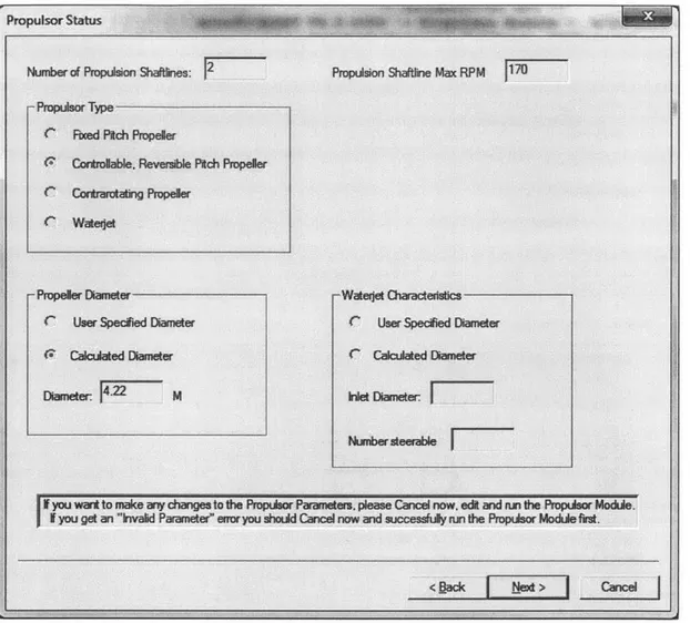
12 Machinery Wizard and Machinery SC Module 73 12.1 Propulsor Status ... ... 73
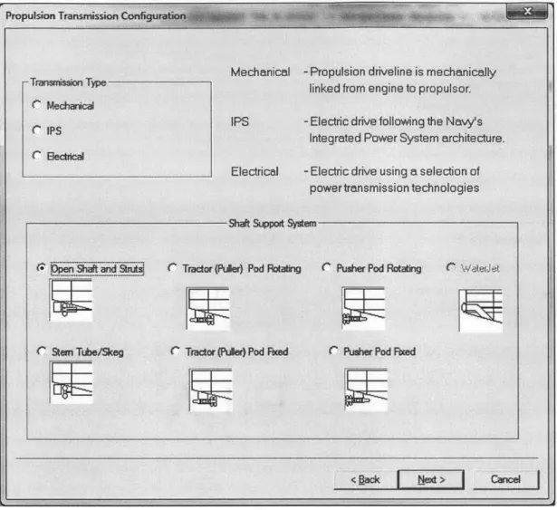
12.2 Propulsion Transmission Configuration . . . . 74
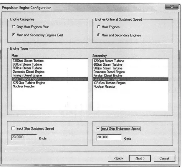
12.3 Propulsion Engine Configuration . . . . 77
12.4 Ship Service Configuration . . . . 79
12.5 Propulsion Arrangement Selection . . . . 81
12.6 The Mechanical Propulsion Ship . . . . 81
12.6.1 Propulsion Arrangement Positioning . . . . 81
12.6.2 Main Propulsion Engine Specifications . . . . 84
12.6.3 Secondary Propulsion Engine Specifications . . . . 87
12.6.4 Ship Service Engine Specifications . . . . 88
12.7 The IPS Ship . . . . 88
12.7.1 Ship Service Power Conversion Module Specifications . . . . . 88
12.7.2 Propulsion Motor Module Specifications . . . . 88
12.7.3 Main Power Generation Module Specifications . . . . 89
12.7.4 Propulsion Bus Cable Specifications . . . .. 90
12.7.5 Electrical and IPS Propulsion Arrangement Positioning . . . . 91
12.8 Auxiliary Propulsion Specifications . . . . 91
12.9 Running the Machinery Module . . . . 92
13 Auxiliary Systems Module 95 14 Weight Module 99 15 Space Module 101 16 Synthesis 103 17 Meeting the Remaining Requirements 107 17.1 Payloads and Adjustments Table . . . . 108
17.2 Requirements to be Entered Directly . . . . 109
17.3 Finalizing the Hullform . . . . 111
17.4 Topside Design . . . . 114
17.6 Deckhouse Finalized . . . 17.7 P&A Table Finalized . . . 17.8 Final Checks . . . .
18 Troubleshooting
18.1 Hullform Utility Tricks . . . . 18.2 Engine Selection . . . . 18.3 Transverse Bulkheads . . . . 18.4 Deckhouse Tricks . . . . 18.5 ASSET Warnings . . . . 18.6 Topside Design . . . . 18.7 The ASSET Help Function ...
19 Hullform Optimization
20 Engine Selection for Fuel Efficiency A Payloads and Adjustments Table
. . . . . . . . . . . . 129 131 134 141 142 143 143 143 144 145 145 147 153 159
List of Figures
2-1 Create a new ASSET Databank ... 23
2-2 Create a new model. . . . . 23
2-3 New model information . . . . 24
2-4 Synthesis Modules . . . . 25
2-5 Module flowchart . . . . 27
4-1 Hullform Utility . . . . 33
4-2 Opening a hullform database . . . . 34
4-3 Hullform utility - hullform tabs . . . . 34
4-4 Half entrance angle (IE) depiction . . . . 40
4-5 Hullform utility - the Shaper function . . . . 42
5-1 Hull Geometry Module Error . . . . 45
5-2 Model Editor . . . . 46
5-3 ASSET Help . . . . 47
5-4 "Go to Next Invalid Parameter" button . . . . 47
6-1 Add Machinery Rooms . . . . 51
6-2 List View button . . . . 51
6-3 Machinery Room arrangements . . . . 52
6-4 Deck plan veiw number 1 - hull subdivision module graphical report . 52 8-1 Hull deck support types and locations . . . . 58
9-2 Horn rudder . . . . 60
9-3 Integral rudder . . . . 61
11-1 The extent of the Wageningen B-series screws. . . . . 70
11-2 The geometry of the Wageningen B-series screws. . . . . 71
12-1 Machinery Wizard flow chart . . . . 74
12-2 Machinery Wizard - propulsor status . . . . 75
12-3 Machinery Wizard - propulsion transmission configuration . . . . 76
12-4 Efficiency comparison of pusher pod vs. puller pod . . . . 77
12-5 Machinery Wizard - propulsion engine configuration . . . . 78
12-6 Machinery wizard -ship service configuration . . . . 80
12-7 Machinery wizard - mechanical propulsion arrangement selection . . . 82
12-8 Machinery wizard - mechanical propulsion arrangement table . . . . . 83
12-9 Machinery wizard - mechanical propulsion arrangement positioning . 84 12-10Machinery wizard - mechanical propulsion arrangement positioning continued . . . . 85
12-11Machinery Wizard - main propulsion engine specifications . . . . 86
12-12Resistance Module printed report number 2 - Speed-Power Matrix . . 87
12-13Machinery wizard -ship service power conversion module specifications 89 12-14Machinery wizard -propulsion motor module specifications . . . . 90
12-15Machinery wizard -auxiliary propulsion module specifications . . . . . 92
17-1 Opening the Model Editor . . . 107
17-2 The Find function in the Model Editor . . . 108
17-3 Adding rows to the P&A Table in the Editor . . . 109
17-4 Cartoon drawing of major ship components . . . 115
17-5 Forward profile view of AGS and VLS . . . . 115
17-6 Aft profile view of hangar and VLS . . . 116
17-7 Longitudinal bulkhead table entry 1 of 2 . . . 117
17-9 Hull Subdivision Graphic Report - deck plan view . . . . 118
17-lOLarge object space table entry 1 of 2 . . . 118
17-11Large object space table entry 2 of 2 . . . . 119
17-12Plan for the deckhouse design . . . . 121
17-13Plan for the deckhouse design -top view . . . . 121
17-14Deckhouse 3D view . . . . 123
17-15Final P&A Table . . . . 132
17-16Floodable length for 95% permeability . . . . 136
17-17Floodable length for 85% permeability . . . . 136
17-18Final Ship - floodable length for 95% permeability . . . . 138
17-19Final Ship - floodable length for 85% permeability . . . . 138
17-20Final Ship - floodable length for 70% permeability . . . . 139
19-1 Example Speed-Time Profile . . . . 20-1 Standard SFC vs. power curve for diesel and gas turbine engines [161 20-2 Example power-time profile [7] . . . . 20-3 Results for a ship with only one type of engine compared to the DDG 51 and the DDG 1000 with the example power-time profile [7] . . . . . . . 149
154 155
List of Tables
3.1 Requirements ... 29 10.1 Holtrop and Mennen principle hull characteristics . . . . 66
Chapter 1
Description of Tools Used
In this document:
1. "Quotations" indicate a function or a button that the user can select. 2. Bold text indicates an entry that the user will make.
3. Italics text indicates an entry from the Model Editor. 4. Typewriter text indicates a file name entry.
1.1
Leading Edge Architecture for Prototyping Ships
(LEAPS)
The Leading Edge Architecture for Prototyping Ships (LEAPS) was designed and is maintained by the Naval Surface Warfare Center, Carderock Division (NSWCCD). It is "a product model repository used by the Naval Sea Systems Command" (NAVSEA). LEAPS provides a means for analysis of ships on many different levels. It is a major design tool used in concept studies, analysis of alternatives, and operational scenarios. [12]
The LEAPS environment is compatible with several of the tools used in this paper. It was designed so that the ship evaluation tools would be able to perform detailed analysis on ship models. In the LEAPS environment, there are analysis tools for
resistance assessments, seakeeping, intact and damaged stability, cost, arrangements,
etc. The LEAPS environment allows the user to quickly move the ship model from one tool to the next for analysis.
1.2
Advanced Ship and Submarine Evaluation Tool
(ASSET)
The Advanced Ship and Submarine Evaluation Tool (ASSET) is a ship design tool that attempts to create a model of a ship based on user inputs. It uses parametric data
from previously designed ships and it contains common naval architecture equations
to determine the ships feasibility. It is compatible with the LEAPS environment and was also created by NSWCCD. The version used for this paper is ASSET 6.3.0.8 The main source for this document is the ASSET User's Manual [13].
A naval architect must pay careful attention to the model to assure it meets the
desired standards. This document will attempt to point out both the benefits and
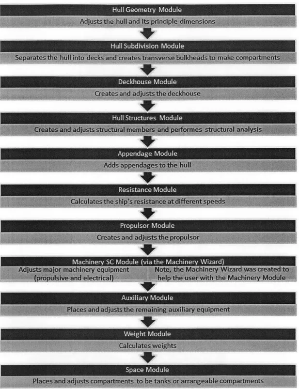
limitations of using such a complicated program. ASSET uses a series of Modules (see
Figure 2-4) to generate or alter certain parts of the ship model. These modules contain internal calculations that perform steps such as creating ship geometry, arranging components, evaluating stability, etc. to ensure feasibility for each respective category.
This paper will step through each of these Modules in detail to explain their inner workings so the designer can have a better understanding of the tool.
When working in ASSET, it is wise to use the "Save As" feature often, especially before big changes are made to the model. The message window at the top of the program contains useful information. It explains what the program is doing behind
the scenes, it posts warnings and errors, and it can provide other useful information. Check this window often and especially when problems arise to try to troubleshoot.
1.2.1 Hullform Utility
ASSET 6.3 contains a tool that was created to quickly make minor adjustments to hullforms. This tool is called the Hullform Utility. This tool is not used to create new hulls. It requires the user to import a pre-made hull from a library. The 2N Department at MIT stores a hullform library (titled Hullf ormLibraryV63 .pdbIndex)
on computers that have ASSET installed. This library contains a wide assortment of hulls. Some of the hulls have been built or are being built currently and some of the hulls are for design studies only. The major hull lines and the general shape of the hull cannot be transformed in the Hullform Utility, but the principle dimensions and major angles can be adjusted. This will be explained in greater detail in Chapter 4.
1.2.2
Machinery Wizard
The Machinery Wizard is a tool in ASSET 6.3 that simplifies the process of arrang-ing the ship machinery usarrang-ing the Machinery Module. When run for the first time, the Machinery Wizard populates many items in the Model Editor that explain the machinery equipment and machinery rooms. The Machinery Wizard is a great tool for making quick adjustments to those machinery elements of the ship without having to adjust multiple variables in the Model Editor. Chapter 12 explains this tool and provides an example of how to use the Machinery Wizard.
1.2.3
Ship Synthesis Tool
The Ship Synthesis tool in ASSET 6.3 is the final step in creating a complete working model. The Synthesis Modules will be explained individually in this paper and once all of them are able to run successfully, the Ship Synthesis tool will attempt to get all-of the outputs of the model to agree within a certain tolerance. For example, if the Hull Subdivision Module creates machinery rooms that are 10m long and the Machinery Module requires the machinery rooms to be 12m in length, the Ship Synthesis tool will adjust that parameter and iterate through the modules again until they can agree on a proper length for the machinery room. When a Ship Synthesis has run
successfully, ASSET will list any warnings or errors in the message window to alert
the user of anything that may deem the ship unfeasible. By successfully completing
a Ship Synthesis, the user can be more confident in the feasibility of the design, but
it does not necessarily mean that the ship is a good one. Chapter 16 will discuss the Ship Synthesis process and give an example of using the Ship Synthesis tool.
1.2.4 Focus Utility
Once a ship has completed the Ship Synthesis process, it can be run through the Focus Utility in ASSET 6.3. The Focus Utility's goal is to create a file that will be recognized in the LEAPS environment. Other advantages to running the Focus Utility include the ability to export three-dimensional drawings of the hull, decks,
bulkheads, and major components of the ship into common file formats that are
readable to commercial software.
1.3
Integrated Hull Design Environment (IHDE)
The Integrated Hull Design Environment (IHDE) is another NSWCCD program that is compatible with the LEAPS environment. IHDE can perform resistance assess-ments and seakeeping analysis by using Computational Fluid Dynamics. This paper will use IHDE to optimize a hullform by minimizing resistance. Chapter 19 will
explain this process.
1.4
JMP 11 Statistical Software
JMP statistical software (version 11) was used as a tool to aid with the Design of Experiments (DoE) approach to the hullform optimization in chapter 19. It is com-mercially available from the company SAS.
Chapter 2
Starting with ASSET 6.3
This paper is designed for a user who has a background in the basics of naval archi-tecture. The paper will follow the design spiral approach of creating a ship with a given set of requirements listed below. The intent is to explain the thought process behind design decisions and how they affect the design process. This is by no means the only way to design a ship using ASSET. Every design involves different challenges and this paper tries to capture and discuss some of those challenges.
2.1
Basic Interface Setup
The basic setup for the ASSET 6.3 interface has a tool bar across the top row. Below that is a message window that stretches across the entire screen. The message window explains the major processes that are being run. It also displays warnings and errors throughout the process so the designer can quickly check the model for feasibility. When warnings appear, the modules will still run, but the feasibility may be in question. It is up to the designer to decide if the warnings are pertinent. Errors will cause a process to stop running. Until fixed, the process will not be able to run. Sometimes, since ships are extremely complex systems, errors can be very difficult to pinpoint. This is why it is recommended to "Save As" often.
Below the message window are a row of buttons. They are as follows: "New bank", "Open Databank", "New Current Model", "Open Current Model from
Data-bank", "Save Current Model to DataData-bank", "Toggle Module Run Manager", "Tog-gle Model Editor", "Tog"Tog-gle Synthesis Manager", "Tog"Tog-gle Report Manager", "Cut", "Copy", and "Paste". The first five buttons are database and model tools and the next four buttons toggle tools on and off so they appear in the main window (which takes up the majority of the screen). A database is simply defined as a collection of ship models. When designing a ship, the user will likely use the "Save As" feature often. This feature must be selected from the File menu. When "Save As" is used, a new model is created in the current database. The bottom row of the ASSET window shows the Model Type, Databank, and Model that is currently open.
The tools that can be toggled will be the main features used in ASSET. The Module Run Manager tool brings up the Tools, Synthesis Modules, and Analysis Modules. As modules are run (by double clicking) reports will be generated and stored below each module. The Model Editor tool is in a hierarchical format that allows the user to adjust the models properties. There are thousands of properties that the user has control over, the modules are set up to make this process simpler. The Synthesis Manger is used once all of the modules are created. When the Ship Synthesis is run (as discussed in Chapter 16), reports will be stored in the Synthesis Manger. They are also stored in the fourth and final tool the Report Manager. This tool is just a quick way to view all of the reports that the Ship Synthesis tool creates. All of the reports that are created by the modules are created when Ship Synthesis is run and they are stored in both the Synthesis Manager and the Report Manager.
2.2
Opening a Ship Model
Begin by creating a databank or using an existing databank. In this case, a new databank is created and titled Cruiser-Tutorial. Figure 2-1 shows the location of the "Create New Databank" button.
A new ship (Current Model) is then created titled Baseline Ship. Figure 2-2 shows the "Create New Model" button. When a new model is created, Figure 2-3 appears. Fill out the information and click "OK".
Figure 2-1: Create a new ASSET Databank
Figure 2-2: Create a new model
2.3
Saving in ASSET 6.3
It cannot be overstated that it is important to save early and save often when using ASSET 6.3. Clicking the floppy disc button, which is located next to the "Open Model" button, will save the current model under its current name. There is also a "Save" option in the File drop-down menu. "Save As" will create a new model in the current database. This feature should be used when attempting significant changes
a W
61RIENE
.Re Run View Options lffimdow Help
Figure 2-3: New model information
to the current model. Since it is very difficult to reverse a step once changes have been made, the "Save As" feature should be used often with newer users.
It is important to note the difference between saving the model and saving the data stored in the Model Editor. The Model Editor is used to store detailed information about the ship (over 1500 variables are stored in the Model Editor). When opening the Model Editor to make changes, the user will not be able to open the Ship Synthesis tool, the Module Run Manager, or the Reports Manager. When exiting the Model Editor, ASSET will ask if you would like to save the changes. This will not save the model! This will only save the information entered in the Model Editor. If you exit ASSET without saving the model as described above, the changes will be lost.
New Model Infornation OK
Model Type: Cancel
New Model
Name-Baseline Ship
New Model Classification Level: UNCLASSIFIED
New Model Distribution Restriction-INONE
New Model Distribution Conditions: 101Y
2.4
First Trip Around the Design Spiral
-
Synthe-sis Modules
ASSET allows the user to run a series of Synthesis Modules that will allow the user to create a ship concept. Chapter 4 will discuss the Hullform Utility and how to begin with a hull in ASSET. Then, chapters 5 through 15 will discuss each of the modules in the order that they appear in Figure 2-4.
Figure 2-4: Synthesis Modules
a module for the first time, it will request that the user input certain aspects of the
ship so that the module can successfully run.
Since this is the first trip around the design spiral, many of the choices that can be
made will be left up to ASSET. This can be done by using the CALC option, which means that ASSET will use parametric data to guess values for certain parameters. As subsequent loops are taken around the design spiral, the user should change certain parameters from CALC to GIVEN. ASSET will no longer attempt to adjust a parameter if you define it as GIVEN. The user should be careful when taking this step as it could lead to potential errors. The ship calculations are not always reversible! That means that if the user switches a parameter from CALC to GIVEN, then runs the module, then switches that same parameter back to CALC, the ship may not return to its original state. If an error arises when running the module, that error may not be solved when simply switching the one parameter back. It cannot be emphasized enough how important it is to "Save As" so that this issue does not cause ships to be completely redesigned. This is also why the user is strongly suggested to maintain a design log detailing the exact changes that are made to the model.
Chapter
3
Ship Requirements for an Example
Cruiser
3.1
Requirements
Table 3.1 shows the requirements for the Cruiser being designed.
Variable Goal Threshold Metric
Value Value
Sustained Speed 32 27 knots
Endurance Range - 7500 nm at 20 knots
Endurance Duration
/
- 60 daysStores
Weapons Capacity - 128
#
of VLS cllsService Life Allowance - 10% % of light ship displacement
- 1.0 feet of KG margin
- 20% % of non-propulsive
electri-cal capacity
Crew Size - 250 crew
Table 3.1: Requirements
Required payloads and other requirements:
9 MK 41 VLS (64 cells forward, 64 cells aft; supports ESSM, SM, VLA, TLAM)
" 2 x Quad Harpoon SSM Launcher (fully loaded)
* 2 x Mk 32 Surface Vessel Torpedo Tubes (SVTT; six rounds in tubes)
" AMDR Volume Search (S Band) Radar and SPY-3 Multifunction (X Band) Radar (22-foot array)
" 2 x Mk 16 Close-In Weapons System (CIWS; 16000 rounds in lockers)
" SQS-60/61 Hull Mounted Sonar System
* SQR-20 Towed Sonar
" SLQ-25A Nixie Torpedo Decoy System
" LAMPS Mk III: Hangar for 2 aircraft + 2 VTUAV, RAST, Refueling
" Total Shipboard Computing Environment C4I System " Advanced Integrated Electronic Warfare System (AIEWS)
* Mk 36 Decoy Launching System (DLS) with 4 Launchers and 100 rounds in magazines
* Advanced Identification Friend or Foe (IFF) " Compensated fuel tanks are not permitted " Deckhouse material is steel only
" Average deck height in the hull is a minimum of 9.5 feet.
" Deckhouse blast overpressure resistance is a minimum of 3 psi.
" A Collective Protective System (CPS) is required.
" Maximum allowed draft is 35 feet.
* Transverse Metacentric Height divided by Beam (GMT/B) is between 0.09 and 0.122
" Available volume is greater than required volume for tanks (by not more than 5%)
" Available arrangeable area is greater than required arrangeable area (by not more than 10%)
" Installed electrical power is greater than required electrical power (by not more than 10% with one generator offline in the worst condition)
" Installed propulsive power is greater than required propulsive power (by not more than 5%)
* Intact longitudinal hull girder strength criteria is met in accordance with Ship Design Standards 100-1 [9J
" Intact stability criteria are met in accordance with the Navy Ship's Technical Manual (NSTM), Chapter 96 -Weights and Stability [11]
" Floodable length criteria is met in accordance with Design Data Sheet (DDS) 079 - Stability and Buoyancy of U.S. Naval Surface Ships [4]
" Shock requirements are met in accordance with Military Specification (MIL-S) 901D [10]
3.2
Payloads and Adjustments Table (P&A Table)
The P&A Table (given in Appendix A) includes the data that ASSET will use to account for the added ship payloads. It accounts for added weights at specific loca-tions, deckhouse area required, other arrangeable area required, and power required. The P&A Table includes items such as weapons, sensors, sonar, aviation equipment, and other non-essential systems that will be placed on the ship.
Often, there are times when the Ship Synthesis tool cannot get certain values to converge. This is when the naval architect must then start to investigate the reasons for the trouble. This is the main driver for this paper being set up the way that it has
been. Chapter 18 will describe many common situations that can cause the Synthesis to fail. During the first trip around the design spiral, ASSET will be given most of the power in determining specific aspects of the ship. This will increase the chances of a successful Synthesis at the end. The "Save As" function will be utilized at this point and small changes will be made as we step around the design spiral again. This process will be repeated and incremental changes will be made to the ship to ensure that the model stays within the bounds of the Synthesis tool.
Chapter 4
The Hullform Utility
This chapter will present an approach to designing a hull using the Hullform Utility. When determining which pre-made hullform to use on a new ship design and open the Hullform Utility shown in Figure 4-1. Next, open a hull of interest by clicking the "Open Hullform" button shown in Figure 4-2. Then click on the Hullform Information tab shown in Figure 4-3 once the hull has loaded. A short description of the hull is included under this tab and should assist the user in making a selection on which hull to use. BI lomodations Machinery Wwand 3D Viewer Payimad Utility Focus Utility FigS1theure 41dufts
Figure 4-2: Opening a hullform database
Hufonu Infomabon SHnutrmn kmaon
Figure 4-3: Hullform utility - hullform tabs
4.1
Shaper Tab
The portion of the Hullform Utility where the hull transformation takes place is the Shaper tab. This is where the user has the ability to adjust several key dimensions of the chosen hullform. The Hullform Shape Controls include Linear Dimensions, Full-ness Factors, and Hullform Angle Factors. There are thirteen adjustable dimensions:
1. Length Linear Dimension Factor 2. Width Linear Dimension Factor 3. Depth Linear Dimension Factor
4. Longitudinal Fullness Factor Forward of Midships 5. Longitudinal Fullness Factor Aft of Midships
7. Vertical Fullness Factor Below the Design Waterline
8. Starboard Transverse Fullness Factor
9. Port Transverse Fullness Factor
10. Bow Angle Factor
11. Stern Angle Factor
12. Starboard Angle Factor 13. Port Angle Factor
These can be adjusted to achieve a hull with the desired properties. The user has the ability to adjust the Hullform Shape Controls from -1.000 to +1.000. When adjusting in the positive direction, the factor that is being adjusted will change by the percentage entered. For example, when changing the Length Linear Dimension Factor to 0.100, the Length Overall (LOA) and the Length on the Waterline (LWL) will go up by a factor of 10%. When adjusting in the negative direction, the factor will only change by one half of that percentage. For example, when changing the Width Linear Dimension Factor to -0.100, the Beam at Waterline will only go down by 5%. When the "Linked" buttons are selected, all of the dimensions in that box will be adjusted at the same time by the same amount with the one exception of the Bow and Stern Hullform Angle Factors that are not able to be linked. Sections below will describe the exact parts of the hull that are changed when adjusting the Hullform Shape Controls. Adjusting these shape controls can be an art and can have great results if done with careful attention to detail. An example of how to use these tools to optimize a hullform will be given in Chapter 19.
The Shaper tab also includes real-time drawings of the hull showing the plan, profile, and body plan view of the hull. Principle dimensions of the hull, which are also updated in real time, can be shown for two different drafts at the same time. These drafts are located at the Design Waterline, which is initially chosen by the
original huliform designer but can be changed by the user, and another reference draft (simply called Draft located on the bottom right of the window).
The Solid 3D tab can be used to view the hull in three dimensions as changes are made. The remaining tabs can be used to see other parameters that change as a hull is being adjusted. Sectional Area Curves, Stability Curves, Lines Drawings, and a comparison of the original hull and the transformed hull are all included so that the user can make well-informed decisions on hullform adjustments.
If the hull is adjusted in the Shaper tab and then saved (either by the "Save" button or by selecting Save in the File menu), the changes will be saved and, when that hull is opened again, the values in the shaper tab will reset to zero. If you do not want to change the original hullform, it is recommended to use the "Save As" function to create the new hull. It is also recommended to maintain a record of the values that were changed in order to be able to repeat the changes to the original hullform. That way, all of the changes can be made to the original hullform and the special features of the hull (such as the bow dome and specific lines that the shaper tab does not change) will not be drastically altered from the original design. The Shaper is meant to make small adjustments to a hull; it is not meant to transform one type of hull into another.
4.1.1 Linear Dimension Factors
The Linear Dimensions Factors are simple stretching/shrinking factors that adjust the principle dimensions of the hull. The Length control will adjust the ship length at all transverse locations by the desired amount. The Width control will adjust the Beam at all depths by the amount desired. Similarly, the Depth control will adjust the depth at all longitudinal locations. Simply stated, these factors stretch or shrink the ship to the desired bounds.
4.1.2
Fullness Factors
There are three fullness factors: Longitudinal, Vertical, and Transverse. Each of these contains two locations at which to apply the fullness factors. These two locations are determined by a cutting plane in each direction: midships for the Longitudinal Fullness Factor, the design waterline (DWL) for the Vertical Fullness Factor, and the center-line for the Transverse Fullness Factor. These six shape controls are a little more complicated than the previous set. The Fullness Factors will adjust the hull to become more boxy (more barge-like) when increased and thinner (more streamlined) when decreased. The fullness factors can be used intelligently to allow for more or less arrangeable area on the ship with the compromise of being more or less streamlined. Another way to look at the trade-off would be to add more or less displacement with the effect of increasing or decreasing the form drag.
Adjusting the Fullness Factors can be thought of as filling-in or removing volume in the chosen direction. The Longitudinal Fullness Factor has very little effect on the beam and draft of the ship and only slightly changes the LOA. The displacement volume and weight can change significantly, however. The Vertical Fullness Factor has little effect on the beam or the LOA, but can change the depth slightly. Again, the displacement and weight can change significantly. The Transverse Fullness Factor has little effect on the principle dimensions of length, width, and depth. It mainly affects the volume of the hull in the transverse direction. The user has the ability to adjust these factors and watch how they affect the hull in real time. If there is any question as to what the factor adjusts, the user can see the effects immediately. Adjusting these shape controls can be an art and can have great results if done with careful attention to detail.
4.1.3
Angle Factors
The Hullform Angle Factors adjust the angles of the outer portions of the hull: the bow near the forward perpendicular (FP), the stern near the aft perpendicular (AP), and the port and starboard angles near the point of entry into the water. These
factors will only affect the regions close to the described portion. Adjusting the bow
and stern angle factors essentially tilt the FP or AP. A positive value tilts the top of the FP or AP away from centerline and a negative value tilts them toward centerline.
Adjusting the Port and Starboard Angle Factors allows the user to add flare to a
hull or to make the hull more tumblehome shaped. A positive value tilts the top
of the hull flare angle away from midships and a negative value tilts the hull flare
toward midships. Again, if the user has a hard time picturing what the effect will be when adjusting these parameters, there is a picture that will be updated with each adjustment of the factors.
4.2
Choosing Principle Hull Dimensions with the
Goal of Reducing Hull Resistance
When trying to adjust the Hullform Shape Controls, the user is confronted with a large range of possibilities. The design space that is allowed under these controls is very large and needs to be narrowed somehow to give the desired results. One method that narrows the design space is an approach proposed by Fung [5]. This method was designed using a regression analysis on a large set of hullforms. Eight characteristic factors are considered when designing a hull and each is chosen with the goal of producing a stable, yet streamlined hull. Minimizing hull resistance and therefore the power required to propel the ship is the goal of this method.
When starting Fing's method, the designer should know one or more of a few key parameters about the design: the approximate displacement, the design speed (most
often the maximum speed), and the overall length. Depending on the flexibility of the requirements, each of these three parameters can be tuned to fit the values that the
method suggests. The method uses the dimensions and steps through eight factors
that will give specific ranges to other key principle dimensions. They are listed in order of their effect on the overall residual resistance, the first having the strongest effect.
4.2.1
Speed (V) to Length (L) Ratio (VL)
Based on the regression analysis, Fung found that the ideal range for the speed to length ratio (VL) is approximately 1.3 - 1.4 in order to minimize residual resistance. Equation 4.1 shows how to calculate VL, where V is the speed in knots and L is the length in feet.
v L = V (4.1)
4.2.2
Displacement (D) to Length Ratio (DL)
The next term, displacement to length ratio (DL), is suggested to fall within the range of approximately 70-80. DL is calculated using Equation 4.2, where D is the displacement in long tons and L is the length in feet. Given the length range from the previous calculation, the displacement has a broad range: 3575 LT to 15,500 LT.
D
D L = D (4.2)
(0.01L)3
4.2.3
Beam to Draft Ratio (B,/T.)
B, is the beam of the ship at its maximum section and T, is the draft of the ship at the same longitudinal location as B,. (B,/T2) should be made to be approximately 3 to 3.5, where 3 is ideal. This can be adjusted quite easily in the Hullform Utility.
4.2.4
Prismatic Coefficient (C)
The prismatic coefficient (Cp) is the quotient of the volume and the product of the LBP and the maximum sectional area (Equation 4.3). A prismatic coefficient of approximately 0.58 to 0.6 should be the goal when adjusting ship parameters. The fullness factors can be a quick way to adjust C, without causing major changes to the other principle dimensions.
V = displaced volume of the hull A, = maximum transverse sectional area LBP= length between perpendiculars
4.2.5 Maximum Section Area Coefficient (Cx)
The maximum section area coefficient (C,) (Equation 4.4 is the maximum sectional area divided by the product of the beam and the draft. This value should fall within the range of 0.75 to 0.80 to achieve a low drag hull.
CX = A (4.4)
BT
4.2.6 Half Entrance Angle (IE)
The half entrance angle is the angle located on the waterplane that the ship makes with the centerline and the hull-water interface. The ideal value for the half entrance angle falls around 8-9 degrees. Figure 4-4 depicts the half entrance angle.
Waterline Run Paralel WasdNe Watwlinm Enrne
WataMneln LWL
Half angle of nrn Halfwigle ofentanem_
Figure 4-4: Half entrance angle (IE) depiction
4.2.7 Transom Area Ratio (TA)
The transom area ratio (TA) is the ratio of the transom area to the maximum section area (A.). A transom area ratio of less than 10% is the goal. This means that the goal is to have a small-area transom compared to the maximum sectional area.
4.2.8
Transom Width Ratio (TW)
The transom width ratio (TW) is the ratio of the transom width to B.. A transom width ratio of greater than 75% is desirable. This may seem counter-intuitive when comparing to the ideal TA in section 4.2.7. When looking at these two ratios together, it is clear that the ideal transom is wide, yet shallow.
Some of the values above are not directly controllable using the Hullform Utility. Those values are controlled by the original hullform design. These properties should be considered when selecting a hullform to modify in the Hulform Utility.
Once a baseline ship has been created, there may be some final adjustments that can be made in order to improve the hydrodynamic performance of the hull. Chapter 19 will explore one method of hullform optimization once a baseline ship has been developed.
4.3
Importing a Hull using the Hullform Utility
The hullform that will be used in this example is titled FSC1 for the Future Sur-face Combatant. Double click on Hullform Utility (Figure 4-1) and open an existing database (Figure 4-2). Open Hullf ormLibraryV63.pdbIndex, choose the HFT..Master Library, and then select HFT-FSC1 under the hullform list.
Based on the requirements and the payloads of the ship (found in the P&A Table
- Appendix A), we can make a guess as to what we expect the size of the ship to be. This surface combatant appears to have similar capabilities to the DDG 1000, which has a displacement of about 17,000 LT. There is one major difference between the DDG1000 and this design, however. This cruiser will not be designed with an Integrated Power System (IPS). This difference means that our final ship should have a displacement less than that of the DDG 1000 due to the absence of electrical conversion equipment and main propulsion motors.
Figure 4-5 shows the controls the user can adjust to change the shape of the hull (on the left hand side of the window). These can be found in the Shaper tab. The dimensions have been adjusted to create a ship with a nominal displacement of about
15,000 LT. This is the first major decision that will almost certainly require another
look later in the design spiral. The first trip around the design spiral will give us more information that we can use to adjust these parameters later. After designing the ship in the first design spiral, we will have a better idea if the hull needs to be larger or smaller. Adjusting the hull will adjust the arrangeable area and volume directly. It will also adjust the resistance of the ship, which results in different maximum speeds.
Foe Vier el
7 740(M ) T =6.5M8 (m)
X 95.191 (m) X 951%1 (m)
LOA 19.8(M). 190n(M)
Lw~dLength an WL 181A3 (m) 181A (m):
DphBeam at WL 2.8 m 03 m
LoWWa i NO F wmFa Draft 72W0 (M) 6.M0 (W
Depth at MidW-hips 14.M0 (M) 14M10(m)
Deiplacement Weght ... .. .. .. .. .. .. 153M8 .. ..(ti 11632 (t)
ao. CPvm 09243 0.5921 ( LN hWd .9 s00 .. gur. 4-. H...r t t t tde te i %,W9 am ttwto
of te hl (hiFigbue 4-5: sHulpformtili the Sheraper functio ngl ttebw
ta rfl with )I ti xmpee the Linear Dimension Factorsadajs hmt d olume0 tod the
orgi a F C hull... Zoom.... in on the.... profile vi w to se.hr.teinlcio .oito
th hl i lcte cmard oth hrzota asedlne(te"Daf"lite nFh
bottom rih.Siete""sPha h oiotlln athsteifeto on
of te hll thik aout he hipexiingthe ate ata frwad anle t te bw i
the "Draft" to 7.800m. Notice that this produces a Displacement Weight of about 15,300 MT. We will start with this hull for our baseline ship. Again, only change the following Hullform Shape Controls:
" Length Dimension Factor = 0.100
" Width Dimension Factor = 0.100
" Depth Dimension Factor = 0.100
This hullform will be saved in a new library called Cruiser-Tutorial-Library. Click "Save Hullform As..." under the File menu, click the "New Library..." button, type CruiserTutorial-Library (or whatever name you would like to call your new hullform library), and click "OK." It will be titled Cruiser 1.0 so that future changes can be made directly to that model. In the New Hullform Name box, type the name that you would like to give the new hull (in this case, Cruiser 1.0). Click "OK" and wait. Ignore the error message that might appear. The hullform will be saved in the new library that was created. In order to bring the ship into ASSET, you must re-open the hull by clicking "Open Database" under the File menu and selecting the new hull that was just saved (you may see a window appear asking to save, but you already did that if you followed the steps. Click "Discard".)
Once the hullform has been loaded, without making any changes to the hull, click the red arrow with the blue and white background (top right corner) to import the hullform into ASSET. The DWL may change based on the inflection point on the bow, but that should not be cause for concern at this point in the design. The DWL is simply a reference point and does not affect the position of this ship in the water during the design. It simply affects the reporting of principle dimensions on the DWL on some ASSET reports.
The final decision in the Hullform Utility is whether to add a step to the hull or not. This step refers to a topside drop in the level of the main deck. A step may be added to the bow, the stern, or both. To make the design simpler and prevent the possibility of having too little freeboard in the aft section of the ship, a step will not
be added. Should the user decide to add a step, the Hullform Utility will ask where to place the step and how deep the step will be.
Click "Continue" and "Start" to load the hull in ASSET. The hull can be saved (which usually causes an error to appear) or discarded (which will not result in a loss of data as long as no changes were made after the hull was re-loaded).
Chapter 5
Hull Geometry Module
The Hull Geometry Module is the first module to be run once the hullform has been loaded into the model from the Hullform Utility. The main goal of the Hull Geometry Module is to define the geometry of the hull. The module will perform general naval architecture calculations to determine some principle dimensions of the ship and provide reports detailing these principle dimensions. When running the Synthesis Modules in ASSET, there will be WARNING messages and ERROR messages that appear in the message window. If the module does not have enough information to successfully run, an error message will appear. Sometimes, the module will then open the Model Editor and show the user which variable is causing the module to fail. Occasionally, it will not be clear as to what is causing the failure. Refer to Chapter 18 for tips on how to handle this issue.
To run the module, double click on the Hull Geometry Module to open it. The following error (Figure 5-1) appears:
RoM uf Geomety Modk i
This module requtires tha at a mifnimum the following parameters b populated:
Ship Type Description
Select "OK" and the Model Editor (Figure 5-2) in ASSET will open to the Ship Type Description. Select SC for Surface Combatant. When performing these steps,
if at any point you are curious as to what the options are for each line in the Model Editor, you can right click and click on Definition to open the help file (Figure 5-3) that explains what each option means. We are choosing SC so that the parametric
data for surface combatants will be used when ASSET makes calculations.
Sh P-C fters &bit Charateistia -QShp Commint Table D cunvs Of Form -DWdAM SShwpBehaviorm E Ship Gmeotety q*hi Sodtem
Figure 5-2: Model Editor
Figure 5-4 shows the button that will automatically take you to the next parameter that ASSET needs to have substantiated in order to run the module.
After reaching the final invalid parameter, ASSET will ask if you would like to close the Model Editor. Click "Yes" and when it asks to store, click "Yes" again. "Store" means temporarily save the work that was done in the editor the store function does not save the model in the databank, you must click the "Save" button to do this. Also, remember that "Save As" is a different function and it creates a new model in the databank that you are working with. Run the Hull Geometry Module again. The module successfully runs. You can see this by looking at the messages box at the top of the window and also by noting that a list of reports now appears under the hull geometry module. These reports include both printed and graphic reports that contain a great deal of information. Notice that the principle dimensions of the hull that was created in the hullform utility are the same with a few exceptions. When
exec
-td Bedc Fawad PA
Cwtas fdad ISee I Ship Type Desciption Type: Inickator ASSET 5.3
The parmter ShIR Tvog Description deses the type skip based an the missim requirament ofthe slip. This paeeseteris used to select equatien options witb de modules dsa vy wh the slip type. Valid vabses of tis
=idicateor-SC
SdRa Cossbata TngatesDestmyers,& Criers).
TENDER
Sbips wiended to provide obbe maiteuance and rapai sappont
SE AUF
Seasft ships provide pea-to-pont traospotation of caWo cludkng dry Ad liqid cargoes, and oops for at of the U.S. iinwy servies. These slips we usafly desipgated with a pefiu "T( es. -T-ACS, T-AVB, T-AH etc..
Fwadhrs
slips. This .pti n must be specifed when a wel deck is ideistifed ethe LarMe ObWct Space TUNREP
dez w repleaset andlogistik suppoet ships.
CARRIER
Amrcrft canem (M. CNN).
Figure 5-3: ASSET Help
Figure 5-4: "Go to Next Invalid Parameter" button
leaving the hullform utility earlier, ASSET increased the draft of our hull to 8.36m, which made the bare hull displacement go up to 19,890 LT. This is much larger than we originally intended, so we may need to go back to visit this in order to create a better model. For the time being, we will ignore this issue and continue to create a working model.
When some modules are run, ASSET will create values for parameters found in the Model Editor. Sometimes default values are assigned and other times temporary values are assigned. These can be seen in the message window. Warnings will also show up in this window. Save the model to permanently save the data that was just created by running the Hull Geometry Module. When opening a model in which modules have previously run, the modules will need to be re-run in order to generate the reports. The information was stored in the Model Editor when saved, so the ship will not be altered. Warnings will reappear each time the module is run. Next, we will run the Hull Subdivision Module.
Chapter 6
Hull Subdivision Module
The Hull Subdivision Module has the goal of separating the hull into compartments by creating decks and transverse bulkheads.
When double clicking this module, ASSET requests that you fill in the Aviation
Facilities Indicator and the Hull Subdivision Indicator. Click "OK" and the Model
Editor will open again.
Aviation Facilities Indicator should be set to MINOR AVN since we are required
to have two helicopters in our design. The other options are NONE and MAJOR AVN. The former should be selected if no aviation facilities are required and the latter should be chosen only for aircraft carriers or amphibious assault ships. Hull
Subdivision Indicator will be set to CALC. This option can be one of the most
helpful selections early on in ship design because it determines where the transverse bulkheads will be placed. If you set this to GIVEN, then you will be expected to enter and adjust the transverse bulkheads on your own. By letting ASSET calculate these locations, you are utilizing one advantage of the program, which is its ability to quickly adapt to design changes.
If CALC is chosen for the Hull Subdivision Indicator, ASSET will determine the placement of the transverse bulkheads. The first bulkhead is placed at 5% of the length between perpendiculars (LBP) as a collision bulkhead. The second bulkhead is then placed at the Machinery Room Aft Bulkhead Location, which marks the aft end of the most aft machinery room (as a percentage of LBP). The default value for
this variable is 0.70. ASSET will need machinery room information to continue with the transverse bulkhead placement.
The remaining transverse bulkheads are placed using the Transverse Bulkhead
Spacing. This variable is the percentage of the LBP that ASSET will separate the
remaining transverse bulkheads throughout the rest of the ship. Next, ASSET will place the decks in the ship with a separation distance between 7.5 and 10 feet.
In the Cruiser example, the engine room (machinery rooms or MRs) arrangements must be defined. This model will be initially made to look similar to a DDG51, there will be 4 MRs 2 main machinery rooms (MMRs) and 2 auxiliary machinery rooms (AMRs). The order of the MRs from bow to stern will be AMR, MMR, MMR, and AMR. For survivability purposes, two transverse bulkheads will separate the MMRs, so there will be a compartment between those two. In order to create these, you must right click on the Machinery Room label on the left hand side, "Create Multiple Instances", and choose "3 instances". 6-1 shows this step. This will create 3 more machinery rooms (one was already created when the editor opened).
To view the MRs that you just created, and to edit them all at once, click on the button shown in 6-2
Clicking the button immediately to the right of the one that was just selected will adjust the width of the columns to make viewing easier. It can be toggled between three different settings when in list view. MRs are listed in order from bow to stern. 6-3 shows the table entries that should be completed to arrange the MRs as described above. In column 1, enter AMR, MMR,MMR, and AMR. In column 3, enter 1, 2, and 1 ASSET will fill in the remaining values in the table.
Run the Hull Subdivision Module again. Now the Hull Subdivision Module can run successfully. Notice that the reports that appear once the module has run include transverse bulkhead and deck locations. These locations have not been finalized yet, though. They might change when the Ship Synthesis tool runs. It is good practice when designing the ship to check the reports from the module regularly. Once each module successfully runs, the reports will appear directly below the module under the label "Run... [timestamp]". There are printed reports and graphical reports.
M
M C Vahue trits -Ship Requiemen Ship Cbaracteisics ship 0whaic" ShipcometryMolded Forrm ews
s paceVevM
Hull Subdvsion
vews of COWMpW*Wnt E4 J wws Of M&chry Row r*
SMachinvy VCG MCIa
Machinery CCnSate unnace
Machiney Create nu*pentne
D moth ~Add toF IXVOrites 4k~I
Arrament WstSisan
M&Chiry RomM 6 instances
Det Drive!e A 7 instances
LIsepmrate ipsev
PropuQlPo DNVm 9 instces
Propkion DaWv 10 in0Anes
L Air CAndiionwin F
Figure 6-1: Add Machinery Rooms
] + Madhver Room Type 0
aiw"ROOM OOMM02 Value Uns
Otry Roo
Figure 6-2: List View button
Becoming familiar with these reports will allow the user to be able to quickly find information about the ship. Figure 6-4 is an example report from the Hull Subdivision
Figure 6-3: Machinery Room arrangements Module. monoSC/ASSET ** UNCLASSIFIED ANY ** V6.3.0000 - HullSubdivision Module - 4/17/2014 12:32:11 DATABANK-TutorialDatabank SHIP-Ship 3.3 GRAPHIC DISPLAY NO. 1 - HULL DECKS AND PLATFORMS
DECK AREA, TOTAL SHIP TOTAL HULL 01 LEVEL (DECK NO. 1) M2 2442.3 ARR AREA, M2 4952.9 VOLUME, M3 28193. -F-i-1 FP .0 0.9 0.8 0.7 0.6 0.5 0.4 0.3 0.2 0.1 0.0 I I I SCALE 0 20 40 60 M
Figure 6-4: Deck plan view number 1 -hull subdivision module graphical report
MMR1 r- -i A-R2 MMR2 AMI I P
Chapter 7
Deckhouse Module
The next module that will be run is the Deckhouse Module. As the name implies, this module creates and adjusts the Deckhouse. The Deckhouse Geometry
Indica-tor can be set to GIVEN, REVISE, or GENERATE. GIVEN implies that the
user will input the parameters in the Deckhouse Compartment list in the Model Edi-tor. REVISE should be chosen if there is currently a defined deckhouse that needs modification. The parameters that will adjust the deckhouse in this mode are the
Deckhouse Size Indicator, the Deckhouse Input Indicator, and the Deckhouse Beam Link Indicator. The Deckhouse Size Indicator uses the Deckhouse Forward Limit, the Deckhouse Aft Limit, and/or the Total Deckhouse Arrangeable Area Required to set
the limits on the size of the deckhouse. The Deckhouse Input Indicator determines how the deckhouse compartments are referenced (either from the lower and upper corners or from the lower corners and the side angles). The Deckhouse Beam Link
Indicator determines whether or not the deckhouse corners should be adjusted if the
beam of the ship changes. Finally, if GENERATE is chosen for the Deckhouse
Geometry Indicator, the following parameters are used to automatically generate the
deckhouse:
" Deckhouse Forward Limit " Deckhouse Aft Limit