HAL Id: hal-00647492
https://hal.archives-ouvertes.fr/hal-00647492
Submitted on 2 Dec 2011
HAL is a multi-disciplinary open access
archive for the deposit and dissemination of
sci-entific research documents, whether they are
pub-lished or not. The documents may come from
teaching and research institutions in France or
abroad, or from public or private research centers.
L’archive ouverte pluridisciplinaire HAL, est
destinée au dépôt et à la diffusion de documents
scientifiques de niveau recherche, publiés ou non,
émanant des établissements d’enseignement et de
recherche français ou étrangers, des laboratoires
publics ou privés.
RFI mitigation at Nanc¸ay Observatory: Impulsive
Signal Processing
Dalal Ait-Allal, Cedric Dumez-Viou, Rodolphe Weber, Grégory Desvignes,
Ismaël Cognard, Gilles Theureau
To cite this version:
Dalal Ait-Allal, Cedric Dumez-Viou, Rodolphe Weber, Grégory Desvignes, Ismaël Cognard, et al.. RFI
mitigation at Nanc¸ay Observatory: Impulsive Signal Processing. S. A. Torchinsky, A. van Ardenne,
T. van den Brink-Havinga, A. van Es, A.J. Faulkner. Widefield Science and Technology for the SKA
SKADS Conference 2009, ISBN 978-90-805434-5-4, pp.201 - 205, 2010. �hal-00647492�
SKADS C 2009
S.A. Torchinsky, A. van Ardenne, T. van den Brink-Havinga, A.J.J. van Es, A.J. Faulkner (eds.) 4-6 November 2009, Chˆateau de Limelette, Belgium
RFI mitigation at Nanc¸ay Observatory:
Impulsive Signal Processing
D. Ait-Allal
1, C. Dumez-Viou
1, R. Weber
2, G. Desvignes
3, I. Cognard
3, and G. Theureau
1,31 Observatoire de Paris, Station de radioastronomie, F-18330 Nanay, France 2 University of Orlans, Site Galile, 12 rue de Blois, 45067 Orlans cedex 2, France
3 Laboratoire de Physique et Chimie de l’Environnement et de l’Espace, UMR 6115 CNRS, F-45071 Orlans Cedex 02, France
Abstract. Radio astronomy has protected frequency bands for free observations. However, it is often necessary to observe outside of those sanctuaries. For example, it is the case for HI radio-sources with high red-shifts that are observed into radar-allocated frequency bands. A radar pulse blanker based on statistical analysis has been implemented in a FPGA. Several tricks has made the implementation possible at a low hardware cost. Pulsar is another kind of impulsive signal which needs specific processing. In the proposed approach, the cyclostationarity is used to discriminate between radio-frequency interference (RFI) pulses and pulsar pulses.
1. Introduction
Nanc¸ay Decimeter Radio telescope, a single antenna telescope, suffers from local ground based Radar RFI while observing red-shifted H1 recombination lines and pulsars. Pulsar also produces periodic pulses which can be measured with dedi-cated backends. Radar interferences enter the receiver through low gain side lobes located in the back of the antenna or in the high gain main lobe after direct reflection on an airplane.
Some work has been done to detect and remove such RFI (Ellingson 2003, Dong 2004). However, the complexity of im-plementation of such algorithms in FPGA logic was a dead-lock. To allow HI surveys in this frequency band, an ana-log waveform blanker has been built and operated in Nanc¸ay Observatory (Weber et al. 2005). However, only strong pulses could be removed, resulting in unworkable results.
In the first half of this paper, we present a digital radar pulse detector based on a power criterion that triggers wave-form blanking. Such detector is the most robust that can be thought from a signal processing point of view, i.e. you bring the least information possible about the RFI to detect. Here, the RFI is detected by an excess of energy during some pe-riod of time. Nevertheless, detection performances are usually very poor. Thus, we included several elaborations that do not strongly bear upon implementation cost but provide significant improvements.
In the second half of this paper, we present another RFI de-tector dedicated to pulsar observations. It will be implemented in the new coherent dedispersion receiver located in the Nanc¸ay Radio Telescope also described in this paper.
2. Pulsed-RFI detection with a power detector
In order to be efficient, the power detector needs a robust esti-mation of the decision threshold. Outlayer samples that go past this level are considered as interferences and trigger the blank-ing of the correspondblank-ing data bloc before it enters the spectral
estimation process. The issue is that the same bloc of data is used for threshold estimation and detection.
2.1. Threshold calculation
Uncorrupted complex data samples follow a normal distribu-tion law since they result from the observadistribu-tion of a radioastro-nomical source more or less buried under system noise, both ideally following a Gaussian distribution. Thus, the instanta-neous power of data samples follows a χ2distribution with two
degree of freedom.
Usually, power detectors are based on a Gaussian model. Actually, there are several disadvantages to use such approach. First, 2 parameters are needed to model the Gaussian distri-bution, mean and standard deviation. Further more, standard deviation estimation requires prior mean estimation. The error made on the mean estimate will affect the standard deviation estimate as well. Finally, in terms of logical resources and data bus width, the implementation cost of such approach could be an issue (Hampson et al. 2002).
Our approach is based on the χ2 distribution model. So,
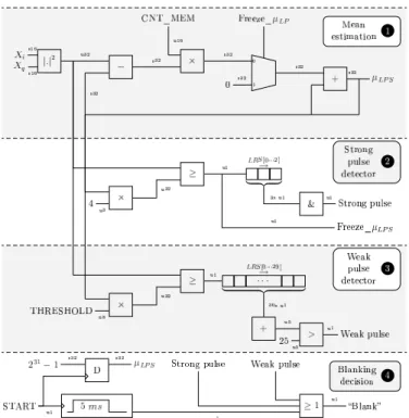
only one parameter (the mean µ) is needed to fully define the signal statistics. Consequently, the threshold value S is calcu-lated like S = Cµ with C a parameter defined by the user. The mean value is recursively estimated (see Fig. 2-1). To make this estimation robust against outliers due to RFI, the strongest sam-ples are systematically discarded. The effect of this clipping on mean estimation can be theoretically derived (Dumez-Viou 2007) and the proper correction is included in the parameter C. From this basic scheme, two improvements are proposed to enhance the performances for strong and weak radar pulses.
2.2. False alarm rate reduction
In detection systems, a given threshold defines a false alarm rate: samples that should not be classified as RFI, trigger the detector because they lie in the right tail of the uncorrupted
2 D. Ait-Allal, et al.: RFI mitigation at Nanc¸ay Observatory: Impulsive Signal Processing
signal distribution, over the threshold value. This value has to be chosen such that false alarm rate is kept at a reasonably low level. Detecting weaker radar pulses can be achieved with a reduced threshold value leading automatically to an unbearable rate of false alarm. Moreover, for synchronisation reasons (see section 2.3), our detector blanks the whole bloc of data even if only one outlier has been detected in that bloc. This approach worsens the false alarm issue. For example, if the threshold is set to 4µ to produce a 2.75% false alarm rate, a 2048-sample bloc configuration will systematically triggers the detector and the receiver returns no usable results.
To overcome this issue, notice that the time distribution of such false alarms over the whole observation is uniform. Let α be the false alarm rate. Then, the probability to get N consecu-tive uncorrupted samples that trigger the detector is αN. Thus,
triggering the blanker if three consecutive samples go past the threshold sets a new false alarm rate of (2.75%)3=2.1×10⁻³
% leading to the blanking of only 6.4% of the data blocs.
The hardware required to handle the previous modifications is limited to a one-bit wide (N − 1)-bits deep shift register to store the results of the comparisons between samples and threshold, and a N-bits AND gate. This approach (S = 4µ, N = 3, α = 2.75%) is used to detect strong radar pulses (see Fig. 2-2).
For weak radar pulses, looking at N consecutive samples lead to poor detection performances. Indeed, radar bursts get more and more buried under the system noise. However, tests have shown that counting the number of detection in a time window is better. Thus, for our weak pulse detector (see Fig. 2-3), we set the threshold to 0.8125µ, the time window to 30 samples and the triggering number of detection to 25. Using binomial law and tabulated χ2distribution, a false alarm rate of
1.2 × 10⁻³
% is achieved, resulting in the blanking of 4% of the data blocs.
In term of implementation, rather than adding the 30 bits for each new sample, we recursively calculate the sum. The balance (-1, 0 or +1) of ’1’ entering and ’1’ leaving the shift register is added to the previous count. The hardware now ex-tends to a one-bit wide 30-bits deep shift register, a 1-bit sub-tractor and a 2-bit/5-bit adder.
Improving a basic power detector implies including some a priori knowledge. We focused on the pulse length that is one of the basic characteristics shared by many radar systems. This way, the detector is still generic but provides better per-formances for a slight increase in hardware costs.
The performances of our detectors are shown in Fig. 1. The blue curves annotated SP (respectively, WP) corresponds to the behaviour of the strong pulse detector (respectively, weak pulse detector). The results ot two other previous studies have been also included in the figure. Niamsuwan et al. (2005) are based on a simple pulse detector for 2 different setting (PP30 and PP90). Dong et al. (2004) results are based on a much more advanced algorithm that gives better performances for its finest setting (AD05 and AD10). However, it includes a lot of in-formation about a specific radar pulse shape. Any radar pulse whose shape gets to far from the model will not be detected as easily.
Fig. 2. Hardware for the radar pulse blanker. LRS is a Logical Right Shift unit. s.. and u.. specify the databuses width for signed and un-signed operands.
2.3. Constrained Blanking
Blanking data blocs of waveform is not harmless. It was care-fully studied in Niamsuwan et al. (2005). In our design, we simply blank data blocs that are synchronized with the data blocs used to perform spectral analysis. Thus, no discontinu-ities are present in the data bloc sent to the FFT. The drawback of such method is that frequency resolution (i.e. FFT size) im-poses the granularity of the blanking. For our design, this leads to an unnecessary amount of blanked data (coarse-grained). For other designs, this might lead to fine-grained blanking that can be adjusted to will with simple glue logic.
2.4. Hardware ressources
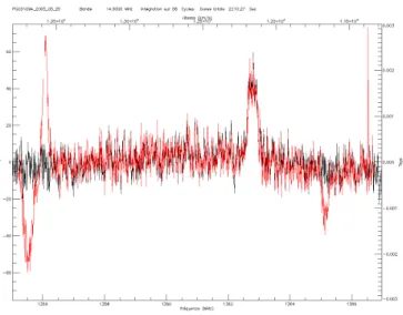
The hardware that computes the mean estimation and the de-tection of strong and weak pulses if presented in the figure 2. The design operates at a maximum sampling rate of 145 Ms/s. However, we only used it at 14 Ms/s which implies no more than 3 radars in the observing frequency band. The overall blanking rate is about 4% but this figure could significantly increase for a wider band carrying many more radars. The logical gates used to implement the algorithm occupies 4% of a 3 Mgates FPGA (Virtex II from Xilinx) and 2 of the 96 18×18-multipliers available. The design has been used to ob-serve radio-galaxies with flux densities as low as 5 mJy. No radar residuals could be seen on the base line as shown on fig-ure 3.
The next section will present another RFI mitigation appli-cation.
Fig. 1. Probability of detection of several detectors as a function of radar pulse Interference to Noise Ration (INR). AD05 and AD10 refer to Dong et al. (2004). PP30 and PP90 refer to Niamsuwan et al. (2005). WP and SP refer to the proposed hardware.
Fig. 3. Observation of PGC051094 with (black) and without (red) blanking.
Fig. 4. Pulsar pulse profile: (a) Time representation of the aver-age power pulse profile of the pulsar J0034-0721 after coherent de-dispersion but with RFI signals. (b) Time representation of the aver-age power pulse profile of the pulsar J0034-0721 after coherent de-dispersion and with RFI signals blanked (with other RFI mitigation scheme).
3. Pulsar application
The quality of pulsar observations is limited by RFI gen-erated by various (and growing) Telecommunications activi-ties. Figure 4 gives an example of the distortion induced by RFI on pulsar observation. This section will present the inno-vative pulsar instrumentation based on Graphical Processing Units (GPU) which has been designed at the Nanc¸ay Radio Astronomical Observatory. In addition, first simulated results on RFI cyclostationary detectors, which will be implemented on the system, will be described.
3.1. Hardware Implementation
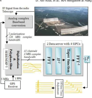
During their travel through the interstellar medium (ISM), these pulsar pulses are progressively attenuated and spread over time (i.e. pulse higher frequency component will arrive ear-lier than the pulse lower one). This phenomenon, named as dispersion, makes these pulses barely detectable without a de-disperion processing. Figure 5 shows the signal dataflow from the radio telescope to the final de-dispersed pulses. The differ-ent steps are described below:
1. The Analog System [Demorest et al. (2007)]: two or-thogonal polarization signals from the radio telescope are downconverted through a custom circuit board quadrature downconverter (QDC). Each QDC handles one polariza-tion and performs a quadrature demodulapolariza-tion providing 128 MHz complex bandwidth which is sent to the SERENDIP5 Spectrometer for digitalization and channelizing.
2. The SERENDIP5 Spectrometer [Demorest et al. (2007)]: SERENDIP5 has been designed by the CASPER group in Berkeley. For this application, it contains four 8-bit analog to digital converters (ADCs) that can be clocked up to 200MHz. A logic programmable device (Virtex 2 XC2V4000 from Xilinx) is used to perform a 32 channel polyphase filter bank (PFB). The channel output bandwidth is 4 MHz complex. An additional Xilinx device (Virtex 2 XC2V1000) is used as a reconfigurable backend processor which can pass data to an independent computer.
3. Data servers: This is the innovative part of the design. The two data severs have two main processings steps. The first one is to read the raw data in from the SERENDIP5 spectrometer and reorganize them from a channel-order to single-channel time ordered chunks. This step is controlled by four micro processors, that send these chunks to four GPUs (Graphic Processing Unit- NVIDIA 88 GTX 128 parallel processors) for the final processings step. The data are then read by the dedispersion program that performs the following tasks:
– Convert raw data from binary to floating point. – Apply a Fourier transform of appropriate length (8192
bins).
– Multiply by the frequency response of de-dispersion fil-ter and the taper function.The taper function is used to avoid aliasing in the low-pass filtering. The combina-tion of the inverse of the dispersion transfer funccombina-tion and the taper function is known as the chirp function. – Inverse Fourier transform back to the time domain.
4 D. Ait-Allal, et al.: RFI mitigation at Nanc¸ay Observatory: Impulsive Signal Processing
Fig. 5. Description of the instrumentation for pulsar observations which is in operation since July 2008 at Nanc¸ay Observatory. The top right hand corner picture is the giant decimetre radio telescope of Nanc¸ay. The GPS receiver provides SERENDIP5 clock synchro-nization through a one pulse per second (1PPS) signal and oscillator synchronization through a 5 MHz reference clock.
– Detect the data to get power versus time, and crossmul-tiply polarization terms.
4. Time adjustment: offline resynchronisation of all the chan-nels.
This coherent de-dispersion pulsar receiver is operational since July 2008 at Nanc¸ay Observatory and it outperforms the per-formances of the previous system based on a cluster of 77 bi-processor Athlon 1.2 GHz. In the next section, a RFI mitiga-tion technique, which is able to separate pulsar pulses from RFI pulses, is presented.
3.2. RFI Cyclostationary Detector
The proposed detector is based on RFI specific properties named cyclostationarity (Serpedin et al. 2005; Gardner et al. 2006; Feliachi et al. 2010). Indeed, most of telecommuni-cations signals present a hidden periodicity which is usually scrambled by the intrinsic signal randomness. For example, this hidden periodic characteristic can be generated by the carrier frequency or the baud rate of the incoming RFI.
In Weber et al. (2007), we have studied the statistics of a cyclostationary detector based on the following criteria:
Cα s = 1 N N−1 X n=0 s(n)2e−i2παn (1) where α is the frequency related to the hidden periodicity (α is also called the cyclic frequency), s(n) is the input signal. Cα
s is
called the conjugate cyclostationary detector.
0 1000 2000 3000 4000 5000 6000 7000 8000 0.2 0.4 0.6 0.8 1
Conjugate Cyclostationary detector Csα with α=2fc
time(µs) Cs α 0 1000 2000 3000 4000 5000 6000 7000 8000 1 1.5 2 2.5 Power Detector time (µs) Power Time−frequency plane time(µs) frequency(MHz) 0 1000 2000 3000 4000 5000 6000 7000 8000 0 1 2 3 4 (a) ok ok (c) wrong wrong (b) ok wrong wrong detection threshold detection threshold
Fig. 6. Detection of impulsive broadband RFI signals (located at t ≃ 1200µs and t ≃ 5000µs) by using the conjugate cyclostationary detec-tor. 4 pulsar pulses are also visible. a) Time-frequency representation. b) Power detector (N=256 samples). c) Conjugate cyclostationary de-tector (N=256 samples).
In Figure 6, an application of such detector in the case of pulsar observation is presented. For the simulation, we have considered a BPSK (Binary Phase Shift keying) RFI. The pul-sar signal has been generated by a model that we have proposed in Ait Allal et al. (2009). The results show that the cyclosta-tionary detector detects only the bursts while the power detec-tor cannot make the difference between bursts and pulsar.
Depending on where this detector will be implemented in the system, different type of RFI can be detected. Three possi-bilities have been identified on the system architecture defined on Figure 5:
– At the input of the polyphase filter bank, just after the dig-italisation. This configuration is appropriate for impulsive or burst broadband RFI.
– Just after the polyphase filter bank.
– Just after the FFT, in the coherent de-dispersion process. This configuration is appropriate for narrow band and con-tinuous RFI.
By simulation, we have shown that cyclostationary detec-tors can be a very interesting alternative to power detecdetec-tors for pulsar observations.
4. Conclusions
Two RFI detectors have been presented, each of them is adapted to a specific RFI context. It is possible to reduce the ef-fect of RFI on radioastronomical observations if a priori knowl-edge on the RFI can be exploited efficiently.
Acknowledgements. The authors would like to thank Pierre Colom, DS4-T3 task leader, Observatoire de Paris, France, Philippe Ravier, Rachid Harba and Rym Feliachi, all from the University of Orl´eans, France, for supplying them with helpful materials and remarks. The authors also want to thank the European Commission Framework Program 6, Project SKADS (contract no 011938), the R´egion Centre for funding part of this work.
References
Ait Allal, D., Weber, R., Cognard, I., Desvignes, G., Theureau, G. 2009, “RFI mitigation in the context of Pulsar coherent de-dispersion at the Nanc¸ay radio astronomical Observatory,” in Proc. EUSIPCO 2009, Glasgow, Scotland Dong, W., Jeffs B.D., Fisher J.R., “Kalman Tracking and
Bayesian Detection for Radar RFI Blanking” RFI2004, Workshop in Mitigation of Radio Frequency Interference in Radio Astronomy, Penticton, Canada, july 2004
Demorest, P.B. 2007, “Measuring the Gravitational Wave Background using Precision Pulsar Timing,” thesis, Chapter 3, University of California, Berkeley.
Dumez-Viou, C., “Radioastronomical sources restoration from hostile radioelectric environment: Implementation of real-time detectors for dynamic spectra analysis”, PhD thesis, http://tel.archives-ouvertes.fr/tel-00319939/ fr/, September 2007
Ellingson, S.W. and Hampson G.A., “Mitigation of radar in-terference in L-band radio astronomy. Astrophysical Journal Supplement Series, 147:167-176, 2003
Feliachi, R., Dumez-viou, C., Weber, R., Boonstra, A.J 2010, in Proc. Wide Field Science and Technology for the SKA, Limelette, Belgium, S.A. Torchinsky et al. (eds), ASTRON, ISBN 978-90-805434-5-4
Gardner, W.A., Napolitano, A., Paura, L. 2006, “Cyclostationarity: Half a century of research,” Signal Processing, 86
Hampson, G.A., “Implementation of the Asynchronous Pulse Blanker” june 2002. http://esl.eng.ohio-state.edu/ ˜rstheory/iip/docserv.html
Lorimer, D., Kramer, M., “Handbook of Pulsar Astronomy,” Cambridge, United Kingdom: Cambridge University Press, 2005.
Niamsuwan, N., Johnson, J.T., Ellingson, S.W., “Examination of a simple pulse-blanking technique for radio frequency in-terference mitigation. RADIO SCIENCE, 40(3), june 2005 Serpedin, E., Panduru, F., Sari, I., Giannakis, G.B. 2005,
“Bibliography on cyclostationarity,” Signal Processing, 85 Weber, R., Bretteil, S., Coffre, A., Colom, P.,
Dumez-Viou, C., Couratier, P.,Denis, L., G´erard, E., Kenfack, G., Picard, P., Kerdraon, A., Lecacheux , A., Ravier, P., Thomas and P. Zarka, I., “Theoretical and Practical Radio Frequency Interference Mitigation Developments at Nanc¸ay Observatory” URSI 2005
Weber, R., Zarka, P., Ryabov, V.B., Feliachi, R., Grießmeier, J.M., Denis, L., Kozhyn, R.V., Vinogradov, V.V., Ravier, P. 2007, “Data pre-processing for decametre wave-length exoplanet detection: An example of cyclostationary RFI detector,” in Proc. EUSIPCO 2007, Poznan, Poland