Publisher’s version / Version de l'éditeur:
Vous avez des questions? Nous pouvons vous aider. Pour communiquer directement avec un auteur, consultez la première page de la revue dans laquelle son article a été publié afin de trouver ses coordonnées. Si vous n’arrivez pas à les repérer, communiquez avec nous à PublicationsArchive-ArchivesPublications@nrc-cnrc.gc.ca.
Questions? Contact the NRC Publications Archive team at
PublicationsArchive-ArchivesPublications@nrc-cnrc.gc.ca. If you wish to email the authors directly, please see the first page of the publication for their contact information.
https://publications-cnrc.canada.ca/fra/droits
L’accès à ce site Web et l’utilisation de son contenu sont assujettis aux conditions présentées dans le site LISEZ CES CONDITIONS ATTENTIVEMENT AVANT D’UTILISER CE SITE WEB.
Fire Study (National Research Council of Canada. Division of Building Research),
1972-03
READ THESE TERMS AND CONDITIONS CAREFULLY BEFORE USING THIS WEBSITE. https://nrc-publications.canada.ca/eng/copyright
NRC Publications Archive Record / Notice des Archives des publications du CNRC :
https://nrc-publications.canada.ca/eng/view/object/?id=ac4d53d4-6966-475c-bc6d-159089957d1b https://publications-cnrc.canada.ca/fra/voir/objet/?id=ac4d53d4-6966-475c-bc6d-159089957d1b
NRC Publications Archive
Archives des publications du CNRC
For the publisher’s version, please access the DOI link below./ Pour consulter la version de l’éditeur, utilisez le lien DOI ci-dessous.
https://doi.org/10.4224/40001358
Access and use of this website and the material on it are subject to the Terms and Conditions set forth at
A Numerical procedure to calculate the temperature of protected steel
columns exposed to fire
NATIONAL RESEARCH COUNCIL O F CANADA DIVLSION O F BUILDING RESEARCH
-.
.
-
z[:L~.
v-* p-
-f -r $7 3L -
A NUMERICAL PROCEDURE T O CALCULATE T H E TEMPERATURE O F PROTECTED S T E E L COLUMNS
EXPOSED T O F I R E
T.
T. L i e and T.Z.
H a r m a t h y F i r e Study NO. 2 8 of t h e Division of Building R e s e a r c h OTTAWAarch
1972
A NUMERICAL PROCEDURE TO CALCULATE THE TEMPERATURE O F PROTECTED STEEL COLUMNS
EXPOSED TO FIRE by
T. T. Lie and T. Z. Harmathy
ABSTRACT
A numerical technique has been developed for the calculation of
the t e m p e r a t u r e history of protected s t e e l columns in fire. This technique was used for the theoretical simulation of s e v e r a l f i r e t e s t s . A comparison of experimental and theoretical information clearly
showed that the technique i s capable of yielding acceptable accuracy. Some basic assumptions used in previous works have been examined in the light of s e v e r a l numerical studies. It has been
proved that the mechanism of heat t r a n s f e r between the protection and s t e e l c o r e h a s little effect on the s t r u c t u r a l performance of the s t e e l core, and that every p e r cent of moisture in the protection i n c r e a s e s the t i m e of f i r e endurance of the column by about t h r e e p e r cent. INTRODUCTION
Columns a r e the most c r i t i c a l s t r u c t u r a l elements in a building in that their collapse can lead t o the l o s s of the entire structure. T h e r e - fore, the performance of protected s t e e l columns in f i r e h a s long a t t r a c - ted considerable attention in various countries. The conventional
method of obtaining information on this subject i s by standard f i r e endur- ance tests. The possibility of making realistic theoretical estimates h a s been hampered by two factors: (i) the lack of knowledge concerning t h e r m a l properties of the commonly used protecting m a t e r i a l s at elevated t e m p e r a t u r e s and certain rheological properties of steel, and (ii) the complexity of the mechanism of heat flow, especially through physico- chemically unstable solids.
The f i r s t of these difficulties i s not s o serious now a s it was 10-1 5 years ago. During the past decade information has accumulated on the t h e r m a l and rheological properties a t elevated t e m p e r a t u r e s of
many important building materials, among them s t e e l and concrete. The difficulties related to the complexity of heat flow analysis have also been greatly reduced by having the calculations performed by high-speed
computers. Thus many f i r e performance problems that not long ago had t o be solved by experiment can now be solved by numerical techniques.
In previous publications by the Division of Building Research, some numerical techniques have already been described for the calculation of the t e m p e r a t u r e history of various one- and two-dimensional configurations typically employed in walls and floors, and of the deformation history of s t e e l supporting elements, such a s beams, joists, etc. In this paper a numerical procedure will be described which can be used for predicting the temperature h i s t o r y of another important group of building elements, protected s t e e l columns. It will be seen that the r e s u l t s a r e also ap- plicable t o the estimation of the point of failure of these elements in "standard" f i r e s .
PREVIOUS WORK
A considerable amount of theoretical work h a s already been done during the past ten y e a r s in connection with the f i r e performance of protected s t e e l columns. These works represented various approaches t o obtaining analytical solutions of the problem of heat conduction through the protective insulation into the s t e e l core. It was unavoidable, t h e r e - fore, that numerous simplifying assumptions w e r e employed with r e s
-
pect to both the m a t e r i a l p r o p e r t i e s and the heat t r a n s m i s s i o n mechanisms. Consequently, the applicability of the derived formulas i s limited t othose c a s e s in which the assumptions used a r e closely satisfied.
With respect to the modeling of heat transmission mechanisms, the following concepts w e r e employed ( s e e Fig. 1):
(a) The t h e r m a l conductivity of s t e e l i s infinite; in other words, the
t e m p e r a t u r e in the s t e e l c o r e i s uniform over the entire volume ( 1 -8). (b) The thickness of the insulation in relation t o i t s circumference i s
s o s m a l l that the heat flow through it can be regarded a s one-dimen- sional (1 -8).
(c) The t h e r m a l r e s i s t a n c e between insulation and the s t e e l is negligible (1-8).
(d) The t e m p e r a t u r e of the exposed surface of the insulation i s equal t o the f i r e t e m p e r a t u r e (2-4,
6,
8).(e) The variation of the t e m p e r a t u r e a c r o s s the insulation i s approximately l i n e a r (1, 5, 7).
(f) The t h e r m a l conductivity and heat capacity of the insulation can be characterized by constant values within the t e m p e r a t u r e ranges that a r e of i n t e r e s t (2-4, 6-8).
(g) The t h e r m a l capacity of the insulation i s negligible (1, 5, 7).
(h) The a i r enclosed by the protection h a s the s a m e temperature a s t h e s t e e l (2, 33, o r its capacity is negligible (1, 4-8).
(i) The influence of moisture in the insulation i s negligible (4,
6,
8), o rthe m o i s t u r e i s concentrated and evaporated at the inner surface of the insulation (2, 3).
Of course, some of these assumptions, e. g. assumptions (a) and (h), a r e fully justifiable f r o m a practical point of view, and, therefore,
will a l s o be used in the present studies. Yet, with the u s e of m o r e
adaptable numerical techniques, it will no longer be n e c e s s a r y to retain those highly r e s t r i c t i v e assumptions that w e r e previously introduced only t o render the problems amenable t o theoretical solutions.
In the p r e s e n t studies an attempt will be made t o u s e the fewest assumptions possible concerning m a t e r i a l behaviour and heat t r a n s -
m i s siori mechanisms. The unavoidable presence of m o i s t u r e in some
protective m a t e r i a l s will a l s o be taken into account, even though only in a simplified manner. The r e s u l t s will be compared with information obtained f r o m t e s t s . Some of the r e s u l t s will further be utilized t o check out the accuracy of simplifying assumptions used in previous studies.
It should also be mentioned that the applicability of the technique
t o be described i s not limited to protected s t e e l columns.
In
fact,it can be applied t o any assembly consisting of a c e n t r a l c o r e of relatively high t h e r m a l conductivity, surrounded by a square -shaped envelope of much lower conductivity, which is exposed t o radiative heating on a l l
four sides.
It
can also be used for the calculation of the t e m p e r a t u r ehistory of monolithic columns o r beams. NUMERICAL PROCEDURE
The heat t r a n s p o r t in and at the boundaries of the insulation will be formulated with t h e aid of a finite difference method originally described
in Ref.
9
and l a t e r elaborated upon in Ref. 10. This method has been applied t o the solution of f i r e resistance problems in Refs. 11, 12 and1 3 .
The f i r s t step in applying this method t o the present problem i s t o divide the cross-sectional a r e a of the insulating protection into a l a r g e number of elementary regions by the u s e of a two-dimensional network. Since the t h e r m a l conductivity of s t e e l i s normally at l e a s t 20 t i m e s higher than that of the protection, the idealization that the temperature of the s t e e l c o r e i s uniform all over i t s volume s e e m s a justifiable one. Consequently, this two-dimensional network need not be extended over the cross-sectional a r e a of the s t e e l core, the sub- division of which thus can be done on a m o r e convenient basis, as will be described later.
As in a previous numerical study (l3), for practical reasons a diagonal mesh has been selected for subdividing the cross-sectional a r e a of the insulation ( s e e Fig. 2). The elementary a r e a s a r e s q u a r e in the inside of the insulation and triangular at i t s boundaries. F o r each inside element, the temperature at the centre i s taken a s r e p r e - sentative of the entire element. F o r each triangular boundary element, the representative point i s located on the hypotenuse.
Since only columns with square protection will be considered in these studies, it i s possible, owing to four-axes symmetry, to calculate the t e m p e r a t u r e distribution in only one-eighth of the c r o s s -sectional a r e a of the insulation.
As Fig. 2 shows, in an x-y coordinate system a "representative" point of the protection, Pm, (representing region (ma n) o r Rm, n) has the coordinates x = (m-1) A
5 /J2
and y=
(n-1) A5
/
J2. It i s obvious from the figure that only those points of the x-y plane a r e defined for which (m+
n) i s an even number.EQUATION FOR
THE
INSIDE OF INSULATIONA convenient way of obtaining equations for the calculation of the t e m p e r a t u r e h i s t o r y of insulation i s by writing heat balance equations for i t s elementary regions. F o r an inside region h , , (represented by point Pmr ,) the heat balance equation for a unit height of the column covering a short period of At duration i s a s follows:
t kj ~j " + Ikim+l), (n-1) m ) ( 1 ) m, n \ 2 A
5
1 kJ T j-
T~ + ~ m t l ) , ( n t 1) t 'J
(
( m t 1), ( n t 1) m, n ' 2 A5
1The t e r m on t h e left side of this equation expresses the accumulation
of heat in Rm,, during a t i m e interval jAt
< t
r ( j t l ) At. The fourt e r m s on the right-hand side describe t h e heat entering Rm, by conduction
during the s a m e period f r o m the neighbouring regions: R
(m-l), (n-1)'
R
R
R The t e r m s in round( m t 1 n l ( m 1 ( n t 1 ( m t 1), ( n t 1)'
brackets represent the temperature gradients and those in square brackets, the average conductivity of the m a t e r i a l along the respective paths of
conduction. k j
-
-
j \ k ( T m , nj a
etc. ma n (P c)j-
'
j),
etc. m8 n-
( T m , nj and (pc)' represent the values of k and ( P C ) , in other words, k
respectively, at t~&Pemperatur=kqhat prevails at P at t = jAt.
ma n
The k(T) and pc(T) functions, which can be determined experimentally, a r e assumed t o b e known.
If the t e m p e r a t u r e s in all elementary r e ions a r e known at
t
=
jbt, the only unknown quantity in Eq. 1 i s T 6 1 i. e. the t e m p e r a -t u r e at P,,
,
at t=
(j+l) A t . 1t can be c a l c u ~ e s , therefore, fromthe following rearranged form of Eq. 1:
:.
k j+
kj ) ( ~ j-
TJ
\
( m t 1), ( n t 1) m, n (m+ l), (nt 1) m , n)
J IEQUATIONS
FOR
THE OUTERBOUNDARY
O F INSULATIONIn a standard f i r e t e s t heat i s t r a n s f e r r e d from the "furnace" (i. e. f r o m the flames and furnace walls) to a column specimen both by convection and radiation. When the flames a r e of sufficient thickness, r a - diative heat t r a n s f e r i s the p r i m a r y mechanism (14). Experimental
data have indicated (13) that in a f i r e t e s t furnace the transmission of heat to the t e s t specimen i s approximately equivalent t o radiative heat t r a n s f e r f r o m a black body at the so-called "furnace temperature". Consequently, in the present studies the columns will be modeled a s
receiving radiative heat flux f r o m a black body, t h e t e m p e r a t u r e of which v a r i e s according t o the temperature-time c u r v e specified by ASTM E l 19-69 (15). This c u r v e can be described approximately by t h e following expres sion (1 3):
1
- 1
Tf
=
530 t 1530 [ 1-
exp (-3.79553 t'
) ] t 306.74 t zwhich i s only slightly different f r o m the expression recommended by the C e n t r e Scientifique et Technique du Batiment (1 6), and approximates the ASTM standard c u r v e within 11" F in the 15-min to 8-h interval.
The heat absorbed by an elementary s u r f a c e region,
during the period jAt
<
t<
( j t l ) At can be written a s R1, n1F r o m this region heat i s transmitted by conduction t o the two neigh- bouring regions, R2, (n-l) and R2, (nt 1).
Again, a heat balance equation c a n be written f o r Rkn, for the period j A t
< t
i ( j t 1) At, .in which TJ i s the only un ownquantity. By solving i t for T J ' ~ one f i n a k y obtains: 1, n
Although in this equation €. is, s t r i c t l y speaking, a m a t e r i a l and
t e m p e r a t u r e dependent quantity,
it
i s sufficiently accurate t o regard it a s constant in the p r e s e n t studies. Since most building m a t e r i a l s have emissivities in the range of 0.85-0.95
(27), a value of 0.9
will be used. EQUATIONS FOR THE INNER BOUNDARY O F INSULATION AND FOR THE S T E E L COREAs Figure 1 shows, the inner surface of the insulation i s in direct contact with the s t e e l c o r e along a certain fraction,
a,
of i t s surface, and it i s separated by an a i r gap from the s t e e l along a f r a c - tion (1-a)
of i t s surface. Obviously, the mechanism of heat transmission along the a r e a s of contact i s conduction. Through the a i r gap, heat i s t r a n s f e r r e d by radiation and convection. Since the radiative heat t r a n s-
f e r i s predominant, especially at higher temperatures, the convective t r a n s f e r mechanism will not be taken into account in the present studies.The model used in this paper t o describe the mechanism of heat t r a n s m i s s i o n at the triangular elementary regions of the inner surface of insulation i s shown in Figure 3. In this model the total m a s s of s t e e l c o r e i s assumed to be divided into elementary pieces amounting t o the number of elementary regions along the inner surface of the insulation, i. e. into 4 (N-M-1) pieces. It i s further assumed that a fraction
a
of each elementary s t e e l m a s s i s in direct contact with the adjacent elementary insulation surface, and thus receives heat from the insula- tion by conduction, while a fraction ( l a ) of i t s m a s s is a t s o m e distance from t h e elementary surface and receives heat by radiation. Obviously, by varying
a
from 0 t o 1, all possible practical conditions, including pure radiative and p u r e conductive heat t r a n s f e r s t o the s t e e l core, can be simulated. In this way the relative importance of the t r a n s f e r mechan- i s m on the r i s e of t e m p e r a t u r e of the s t e e l c o r e can be studied.The radiative heat t r a n s f e r r e d to the s t e e l c o r e from a ( 1 4 ) fraction of the elementary region R of the inner surface of insula-
m.1 n tion during the period jA< t s ( j t l)A t is
-
where the emissivity factor E , can be calculated approximately from the
Here, again, c and c will be regarded a s constants for the tempera-
i
t u r e ranges considered and equal to
0.9.
Since, by assumption, steel i s regarded a s a perfect conductor, the temperatures of those fractions of elementary s t e e l m a s s e s which
a r e in direct contact with the insulation surface a r e identical to those of the adjacent elementary regions of insulation. Consequently, their presence can be taken into account simply by adding their heat capaci- t i e s to those of the adjacent elementary insulation regions.
Again, from a heat balance equation written for region R
Ms
nfor the period jAt < t
s
( j t l ) A t , the following equation can be derived f o r.j+l
M a n
'where ( c ) j
S M, n i s the specific heat of steel at a temperature that prevails
at
P ~ ,
n at t=
j A t . From available data (17, 18), the following expressionhas been derived for the dependence of c on temperature:
Of course, the p r i m a r y purpose of all these calculations i s t o obtain information on the temperature of the s t e e l core. Again, by the application of the law of conservation of energy, the t e m p e r a t u r e of that (1 -a ) portion of the c o r e which receives heat by radiation i s obtained a s
As has been said e a r l i e r , the temperature of the fraction,
a ,
of each elementary s t e e l m a s s , which i s heated by conduction, i s identi- c a l t o that of the adjacent surface element of the insulation. Theayerage t e m p e r a t u r e of the entire s t e e l c o r e at t = ( j t l ) At, i , e.
T J ' ~ can now be calculated f r o m the following equation:
s a =j+ 1 T j t l 2a N-M
S
C dT=
N-M-1 C j+l n= 3, 5,..
.
S T s ~which i s obtained by expressing the enthalpy of the s t e e l c o r e in two different ways; once with the aid of already defined variables, and once by using T J ' ~
.
s a
AUXILIARY EQUATIONS
As Fig. 2 shows, the following equations a r e applicable to the elementary regions along both sides of the lines of symmetry.
and along line B-C:
.j+ 1
-
-
ma (N-m) ( m t I), (N-mt 1)
With the aid of Eqs. 4, 6, 8, 10, 11, 12 and 13 it i s now possible t o calculate the t e m p e r a t u r e distribution in the insulation and on i t s boundaries f o r any ( j t l ) At t i m e level, if the t e m p e r a t u r e distribution at the jOt level i s known. Initially only the t e m p e r a t u r e distribution a t the t
=
0 level i s known. In f i r e endurance studies the initialt e m p e r a t u r e of the column (insulation and steel) h a s always been taken a s 70" F and uniform; thus
And, s t a r t i n g f r o m the initial condition, with repeated application of Eqs. 4, 6, 8, 10, 11, 12 and 13 the t e m p e r a t u r e h i s t o r y of the p r o t e c - tive insulation and of the s t e e l c o r e of t h e column can be determined up t o any specified t i m e level.
Since in f i r e endurance standards 1 0 0 0 ° F i s usually regarded a s the t e m p e r a t u r e of failure of s t e e l core, the calculations can be terminated a f t e r i t s t e m p e r a t u r e h a s exceeded 1460" R.
E F F E C T O F MOISTURE
Although t h e r e h a s already been a f a i r amount of work done a t the DBR/NRC concerning the effect of m o i s t u r e on the f i r e endurance (19, 20), a l l previous work related to walls and floors. Since i t seemed unlikely that the r e s u l t s of this work could be applied to columns, a different concept had t o be considered to take the p r e s e n c e of m o i s t u r e into account in the p r e s e n t studies.
It i s well known that under n o r m a l atmospheric conditions, i. e. a t room t e m p e r a t u r e and at about 50 t o 70 p e r cent relative humidity, the bulk of m o i s t u r e in building m a t e r i a l s i s in the form of capillary water. The capillary water h a s a f a i r l y high mobility and, a s
numerous observations and theoretical work (19) indicated, under the effect of high p r e s s u r e gradients developing during a f i r e exposure it will move slowly toward the cooler regions; toward the inner s u r f a c e of t h e protective insulation, in the c a s e of a column. It s e e m s reasonable to assume, therefore, that a l a r g e portion of the m o i s t u r e originally
p r e s e n t in the insulation will finally vapourize at the inner surface of the insulation.
A comprehensive computer study was undertaken t o find out
whether the r a t e of moisture migration had any significant effect on the t e m p e r a t u r e h i s t o r y of s t e e l core.
The computer studies indicated that the influence of the r a t e of m o i s t u r e movement was not sufficient to justify the increased
labour involved in a m o r e elaborate formulation of the problem. It
was decided, therefore, that in further work only the limiting c a s e
would be considered, in which the r a t e of moisture migration is infinite;
in other words, all moisture originally p r e s e n t in the insulation i s transposed into the inner surface layer of the insulation right f r o m the beginning of the f i r e exposure. This model can be recognized a s p r a c -
tically the s a m e a s the one already used in Refs. 2 and 3.
The hypothetical moisture concentration in the triangular
elementary regions of the inner surface, after the moisture originally present in the insulation was transposed into these regions, can be written a s follows:
This equation can be verified with the aid of Fig. 2.
Since, according t o this model, moisture exists only in the elementary regions along the inner surface of the insulation, the effect of moisture can be taken into account by modifying the equation
concerned with the temperature of these regions, namely Eq.
8.
Thepresence of m o i s t u r e affects the heat balance for an elementary region, Rm, nr by (i) absorbing latent heat in the vaporization p r o c e s s and (ii) increasing the heat capacity of the regions.
To enable one t o formulate the problem of vaporization of moisture, i t i s n e c e s s a r y to define a function which d e s c r i b e s the fraction of the net heat, supplied t o an elementary region, that i s used for evaporation of moisture on reaching certain t e m p e r a t u r e levels. Since the bulk of evaporation is known t o take place in the vicinity of
the boiling point, i. e. 672" R, the function t o be chosen should obviously
have a steep section a t this temperature. The following function fulfils this requirement:
6
=
i
erfc(
A
where A is a constant, generally taken a s 10 in the present work. When t h e r e i s still moisture in the insulation,a fraction
5
b,
of the net heat inflow in a certain region RM,, is used f o revaporation and a fraction ( 1
-
CL
) for increasing the tempera- r nt u r e of insulation and steel core.
From a heat balance equation similar to Eq. 1, it can be derived that the change of the hypothetical moisture concentration
v n
-
,
)
in an elementary regionRM,
due to evaporation in the period jAt<
t ~ ( j t l ) A t is:The additional heat absorbed by these elementary regions, p e r unit time, due to the presence of (hypothetical) moisture can be expressed a s
-
The t e r m in
[
J
brackets is, in fact, a heat capacity additive to those a l r e a d y introduced in Eq. 8. Thus the f o r m of Eq. 8 modified for the p r e s e n c e of m o i s t u r e and f o r m o i s t u r e evaporation becomes:(18) This equation i s applicable to the calculation of TM, j" a s long a s there
-
i s m o i s t u r e in the insulation, i. e.
coJ
>
0. If the insulation*is d r y ,M, n
o r becomes d r y during the heating process,
i.
e.T J
= 0, T J + ~M, n 1M,n
i s t o be calculated by Eq. 8.
EXPERIMENTAL VERIFICATION
T o verify the validity of t h i s n u m e r i c a l technique, standard f i r e t e s t s w e r e c a r r i e d out on s e v e r a l protected s t e e l columns. The r e s u l t s w e r e then compared with those obtained by the theoretical simulations
of t h e s e t e s t s . In the t e s t s t h r e e different protecting m a t e r i a l s and two different s t e e l c o r e s w e r e used. The effect of the m o i s t u r e content of insulation on the t e m p e r a t u r e h i s t o r y of s t e e l c o r e s was a l s o studied i n a few c a s e s .
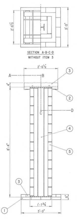
A typical t e s t specimen i s shown in Fig. 4. The description of the components of the specimen i s given below:
1. Insulating f i r e bricks, to reduce heat l o s s e s f r o m the bottom of the s t e e l core.
2. Protecting device, t o contain an insulating m i n e r a l wool. 3. Mineral wool, t o reduce heat l o s s e s f r o m the top of the s t e e l
core.
4. Steel core: H-section.
5. Protecting insulation. In the c a s e shown in the figure the insulation and s t e e l a r e separated all around by an a i r space. S e v e r a l of the t e s t specimens w e r e constructed with the insula- tion in contact with the flanges of the s t e e l section, a s shown in Fig. 1.
The following t h r e e protecting m a t e r i a l s w e r e used: lightweight concrete of expanded shale aggregates, insulating f i r e b r i c k Group 23, and a heavy clay brick. The t h e r m a l p r o p e r t i e s of the lightweight concrete w e r e derived f r o m the data given in Ref. 21; and those of the insulating f i r e b r i c k f r o m Ref. 22. Those of the heavy clay b r i c k w e r e m e a s u r e d for a few t e m p e r a t u r e s according t o the method described in Ref. 22. Since the m e a s u r e d p r o p e r t i e s w e r e approximately equal to those given in Ref. 23, the l a t t e r data w e r e used for the whole t e m p e r a t u r e range under consideration.
The t h e r m a l p r o p e r t i e s of the insulating m a t e r i a l s used, t h e i r m o i s t u r e content before t h e test, and t h e weight and s i z e of the s t e e l c o r e s a r e given in the Tables 1, 2 and 3.
TESTING PROCEDURE
The t e s t s w e r e c a r r i e d out by exposing t e s t specimens to heating in a furnace specially built for this purpose. The heat input into the t e s t furnace was controlled in such a way that the average t e m p e r a t u r e closely followed the standard t e m p e r a t u r e v e r s u s t i m e c u r v e given by Eq. 5. The furnace t e m p e r a t u r e was m e a s u r e d by nine thermocouples located at s e v e r a l levels around the specimen with t h e i r hot junctions 12 in. away f r o m the s u r f a c e of the specimen.
The t e m p e r a t u r e of the s t e e l c o r e was m e a s u r e d at four levels, but because of the s m a l l t e m p e r a t u r e differences between t h e various
locations, only indications by t h r e e thermocouples located at the mid- height of the specimen w e r e used. The average of the t e m p e r a t u r e s recorded by t h e s e t h r e e thermocouples, of which one was located in the c e n t r e of the web and the two others at the edge of either flange, was taken a s a m e a s u r e of the t e m p e r a t u r e of the s t e e l core.
RESULTS
Information concerning the variation of the average t e m p e r a t u r e of s t e e l c o r e a s obtained from the f i r e t e s t s , together with that obtained by theoretical simulations, i s presented in Figs. 5 to 8. In all t e s t s the furnace t e m p e r a t u r e followed v e r y closely the temperature v e r s u s t i m e curve formulated by Eq. 5, and therefore it h a s not been plotted in t h e figures.
Probably because of condensation of moisture on the thermo- couple wires, no reliable information could be obtained of t h e s t e e l t e m p e r a t u r e in the initial stages of those two t e s t s (shown in Figs. 5
and 8) in which the protection contained moisture. These doubtful t e m p e r a t u r e measurements have not been plotted in the figures.
It is seen that in all c a s e s a good agreement exists between experimental and calculated temperatures. This finding also confirms t h e validity of the model used t o account for the presence of moisture.
As mentioned e a r l i e r , in previous works the t h e r m a l r e s i s t a n c e between insulation and the s t e e l c o r e was always disregarded (1 -8). To
check the validity of this concept, calculations w e r e performed for the following t h r e e modes of heat t r a n s f e r f r o m the insulation t o the s t e e l core:
(a) All heat i s t r a n s f e r r e d by radiation t o the c o r e (i. e.
a =
0in Eqs. 8, 11 and 19).
(b) 50 p e r cent of the heat is t r a n s f e r r e d t o the c o r e by radia- tion and 50 p e r cent by conduction; t h e r e i s no t h e r m a l r e s i s t a n c e at contacting s u r f a c e s between the c o r e and insulation
(a
= 0. 5).(c) All heat i s t r a n s f e r r e d by conduction from the insulation to the c o r e without any t h e r m a l r e s i s t a n c e at the contacting surfaces between s t e e l c o r e and insulation ( a
=
1).The calculated t e m p e r a t u r e s of s t e e l c o r e have been plotted against t i m e in Figs.
9
and 10. Fig.9
r e l a t e s t o a column made witha lightweight concrete protection, and Fig. 10 t o a column protected with insulating f i r e brick. It i s clearly seen that the mechanism of heat t r a n s f e r from the insulation t o the s t e e l c o r e has only a s m a l l influence on the s t e e l temperature. It s e e m s justified, therefore, t o neglect the t h e r m a l resistance at the contacting surfaces between s t e e l and insulation, in other words, to assume that the s t e e l temperature i s equal to t h e temperature at the inner surface of insulation.
F u r t h e r calculations w e r e performed t o obtain information on the influence of the moisture content in the protection on the t e m p e r a t u r e of s t e e l core. The r e s u l t s a r e shown in Figs. 11 t o 13.
It i s usual t o regard the time at which the temperature of s t e e l reaches an average of about 1000" F a s the t i m e of failure for the column. At this temperature, s t e e l will have lost s o much of i t s strength that i t no longer can support the load. It i s seen in Figs. 11 and 13 that f o r columns made with lightweight protection of considerable thickness, the gain in time due t o the presence of moisture may be substantial. With the exception of concrete, however, commonly used inorganic building m a t e r i a l s do not hold much moisture under normal atmospheric conditions. An examination of data (24, 25, 26) indicated that while at 50 p e r cent relative humidity concretes can hold 3 t o
6
p e r cent moisture by volume, most other m a t e r i a l s hold l e s s than 1 p e r cent.F r o m the data given in Figs. 11
-
13 it can be derived that the gain in f i r e resistance, i. e. in the t i m e that it takes the s t e e l c o r e t o r e a c h the 1000" F level, due t o moisture in the protection i s roughly3 p e r cent for each p e r cent moisture. Thus, one can expect gains of the o r d e r of 10 t o 20 p e r cent in the c a s e of concrete protection and hardly any gains for other inorganic materials.
CONCLUSIONS
A finite difference calculation method has been described. It can be used for the prediction of the t e m p e r a t u r e history of the insulation and s t e e l c o r e of protected s t e e l columns. The acceptable accuracy of this method has been demonstrated by comparing experimental and theoretical results.
It h a s been shown that the temperature of s t e e l c o r e i s insensitive to the mechanism of heat t r a n s f e r from the inner surface of the insulation to the steel. Thus a close approximation of the average t e m p e r a t u r e of s t e e l c o r e can be obtained by assuming that this i s equal to the average t e m p e r a t u r e
of the inner surface of the protection. To facilitate the calculation of the temperature of s t e e l c o r e it i s permissible t o a s s u m e that all moisture i s concentrated a t the inner surface of the insulation from the s t a r t of the heating process, and evaporates from this surface a s the t e m p e r a t u r e at this place r i s e s .
In general, the influence of moisture on the t e m p e r a t u r e
h i s t o r y of s t e e l c o r e i s negligible for most inorganic building materials. A notable exception i s concrete, for which the presence of moisture may cause a 10 t o 20 p e r cent gain in the time that the column can support the load.
Although the method has been developed p r i m a r i l y f o r the calculation of t e m p e r a t u r e s in protected s t e e l columns, it has a m o r e general applicability. It may a l s o be used t o calculate the t e m p e r a t u r e history in solid s t r u c t u r a l elements, such a s concrete beams and
columns, and unprotected s t e e l for any f i r e exposure. ACKNOWLEDGEMENT
The authors wish t o thank E. 0. Porteous f o r his assistance in conducting the experimental work.
NOMENCLATURE Notations
a empirical constant, " R
c specific heat; without subscript: specific heat of insulation, Btu/lbO R
j = 0, 1, 2,
. .
.
k
t h e r m a l conductivity; without subscript: t h e r m a l conductivity of insulation, Btu/h f t O RM number of m e s h points along x axis
N number of m e s h points along
y
axisP point
R elementary region
t time, h
T temperature, OR (if not specified otherwise) W m a s s of s t e e l core, lb/ft x coordinate, ft Y coordinate, ft Greek l e t t e r s fraction increment o r difference m e s h width, ft emissivity
emis sivity factor
latent heat of vaporization, Btu/lb
density; without subscript: density of insulation, lb/ft 3
-8
Stefan-Boltzrnann constant, 0 -17/3 x 10 Btu/h ft2 o R~
moisture concentration, ft3/ft 3
3 3
Subscripts
a average
f of the "furnace" i of the insulation
m, M at o r around a m e s h point in the m-th o r M-th row, respectively n, N a t o r around a m e s h point in the n-th o r N-th column, respectively
s of the s t e e l c o r e R pertaining t o radiation w of water Superscripts o a t t = O j at t
=
jAtREFERENCES -
1 Geilinger, W. and Bryl, S. Feursicherheit d e r Stahlkonstruktionen, IV. Teil: Feurschutz von Stahlstiitzen, Verlag Schweizer Stahl- bauverband, Zurich, 1962.
2 Fujii, S. The theoretical calculation of t e m p e r a t u r e - r i s e of thermally protected s t e e l column exposed t o the fire. Building R e s e a r c h Institute Occasional Report No. 10, Tokyo, 1963.
3 Pettersson, 0. Utvecklingstendenser rorande brandteknisk
dimensionering av st%lkonstruk tioner, VSg -och vattenbyggar en, No. 6-7, Stockholm, 1964, pp. 265-268.
4 Lie, T. T. Bekledingsmaterialen en Bouwconstructies bij
Brand, Heron No. 2, 1965, pp. 57-81.
5 Witteveen, J. Brandveiligheid Staalconstructies, Centrum
Bouwen in Staal, Rotterdam, 1966.
6 Lie, T. T. T e m p e r a t u r e of protected s t e e l in fire. P a p e r 8
of "Behaviour of S t r u c t u r a l Steel in F i r e ,
"
Ministry of Technology and F i r e Offices* Committee Joint F i r e Research Organization Symposium No. 2, H. M. S. O., London, 1968.7 Berechnung d e s Brandwiderstandes von Stahlkonstruktionen.
Schweizerische Zentralstelle f c r Stahlbau, Zurich, 1969. 8 Law, M. S t r u c t u r a l f i r e protection in the p r o c e s s industry.
Building, Vol. 216, No. 29, 1969, pp. 86-90.
9 Emmons, H. W. The numerical solution of heat conduction
problems. Transactions of the American Society of Mechanical Engineers, Vol. 65, 1943, pp. 607-615.
10 Dusinberre, G. M. Heat t r a n s f e r calculations by finite differences. International Textbook Company, Scranton, Pennsylvania, 196 1. 11 Harmathy, T. Z. A t r e a t i s e on theoretical f i r e endurance rating.
American Society f o r Testing Materials, Special Technical Publication No. 301, 1961, pp. 10-40.
Kawagoe, K. Calculation of t e m p e r a t u r e i n double-layer walls heated f r o m one side. Bulletin of the F i r e Prevention Society of Japan, Vol. 13, No. 2, 1965, pp. 29-35.
Harmathy, T. Z. T h e r m a l performance of concrete m a s o n r y walls in f i r e . A m e r i c a n Society f o r Testing and Materials, Special Technical Publication No. 464, 1970, pp. 209-243.
Thrinks, W. and Mawhinney, M. W. Industrial furnaces. Carnegie
Inst. Technology, John Wiley and Sons, h c . , New York, 1961. Standard methods of f i r e t e s t s of building construction and m a t e r i a l s , ASTM Designation E l 19-69, 1969 Book of ASTM Standards, P a r t 14, pp. 436-452.
F a c k l e r , J. P., "Cahier 299", C a h i e r s C e n t r e Scientifique e t Technique du B2timent, No. 38, A p r i l 1959.
Liley, P. E., Touloukian, Y. S., and Gambill, W. R. P h y s i c a l
and chemical data. Chemical Engineers Handbook, J. H. P e r r y ,
Sec. 3, McGraw-Hill Book Company, New York, 1963. Brit. Iron S t e e l Res. Assoc., P h y s i c a l constants of s o m e c o m m e r c i a l s t e e l s a t elevated t e m p e r a t u r e s . Butterworths Sci. Publ., London, 1953.
Harmathy, T. Z. Effect of m o i s t u r e on the f i r e endurance of
building elements. ASTM Spec. Techn. Publ. No. 385, 1965, p. 74.
Harmathy, T. Z. and Lie, T. T. Experimental verification of
the r u l e of m o i s t u r e moment. F i r e Technology, Vol. 7, 1971, p. 17.
Harmathy, T. Z. T h e r m a l p r o p e r t i e s of concrete at elevated t e m p e r a t u r e s . Journal of Materials, JMLSA, Vol. 5, No. 1, March 1970, pp. 47-74.
Harmathy, T. Z. Variable s t a t e methods of m e a s u r i n g the
t h e r m a l p r o p e r t i e s of solids, J. Appl. P h y s . , Vol. 35, 1964, p. 1190.
P l u m m e r , C. E. et al. Brick, s t r u c t u r a l clay products and r e f r a c
-
t o r i e s . Engineering M a t e r i a l s Handbook, C. L. Mantell, Sect.25. McGraw-Hill Book Company, New York, Toronto, London,
24 Powers, T. C. and Brownyard, T. L. Studies of the physical p r o p e r t i e s of hardened portland cement paste. R e s e a r c h
Laboratories of the Portland Cement Association, Bulletin 22, Chicago, 1948.
25 Harmathy, T. Z. Moisture sorption of building materials,
Technical P a p e r No. 242, Division of Building Research, National Research Council of Canada, Ottawa, NRC 9492, March 1967.
26 Lie,
T.
T. Feasibility of determining the equilibrium m o i s t u r econdition in f i r e r e s i s t a n c e t e s t specimens by measuring t h e i r e l e c t r i c a l resistance. Building Research Note No. 7 5,
Division of Building Research, NRC, Ottawa, 197 1.
27 Gilmor e, C. H. et al. Heat transmission. Chemical Engineer's
Handbook, J. H. P e r r y , Sect. 10, McGraw-Hill Book
TABLE 1
INFORMATION ON THE TEST COLUMNS BUILT WITH LIGHTWEIGHT CONCRETE PROTECTION
3
Density of insulation a t room temperature:
P
= 9 0 lb/ft Average moisture content: cpo=
0.032 £t3/ft3Thickness of protection: 3 5/8 in.
Steel core: H-section, 6 x 6 in., 20 l b p e r ft length.
Outside dimensions of specimen: 19: in. x 192 in. (no contact between s t e e l and protection).
Emissivity of protection: C i
=
0. 9.Emissivity of steel: C s
=
0. 9.T h e r m a l properties of protecting insulation
T h e r m a l conductivity,
(k) ~ t u / f t h O R
P
T e m p e r a t u r e
O F
Volumetric heat capacity,
(p c) ~ t u / f t 3 R 7 0 100 200 300 40 0 500 600
-
-
-16.35 17.00 18.75 23.95 25.10 25.20 24.90 0. 317 0.399 0.320 0. 323 0.323 0.325 0.326 0. 328 0. 327 0. 327 0. 327 0. 320 0. 315 0. 311 0.308 0. 307 0.306 0. 305 0. 303 0.303 0.312 0. 327 0. 342 700 750 800 850 900 950 1000 1050 1100 1200 1300 24.80 25.00 26.60 33.50 41.25 43.30 35.70 27.90 23.90 23.85 25.75 1400 1500 1700 2000 2300 25.25 23.90 24.20 24.65 25.30TABLE 2
INFORMATION ON THE TEST COLUMNS BUILT WITH INSULATING FIRE BRICK PROTECTION
Density of insulation a t room temperature: p
=
45 lb/ft 3 Average m o i s t u r e content: CQ, = 0.Thickness protection: 22 in.
S t e e l core: H-section, 6 x 6 in.
,
20 l b p e r ft length.Outside dimensions of specimen: 11 in. x 11 in. (contact between s t e e l and protection a t the s t e e l flanges)
Emissivity of protection: C i
=
0. 9. Emissivity of steel: C S = 0. 9.T h e r m a l p r o p e r t i e s of protecting insulation T e m p e r a t u r e , Volumetric heat capacity,
(pc) ~ t u / f t ~ "
R
T h e r m a l conductivity, (k) ~ t u / f t h O R 0.098 0,100 70 100 7.21 7.39 200 300 40 0 500 600 700 800 1000 1200 1400 1600 1800 2000 2200 2 400 8. 00 8. 60 9. 14 9. 55 9.88 10.25 10.57 11.12 11.66 12.21 12.76 13. 31 13.86 14. 41 14.95 - 0. 107 0.114 0.120 0. 127 I 0.134 0. 141 0. 148 0.165 0.182 0.204 0.230 0.255 0.281 0. 307 0. 332TABLE 3
INFORMATION ON THE TEST COLUMNS BUILT WITH HEAVY CLAY BRICK PROTECTION
3 Density of insulation a t room temperature: p = 1 3 3 lb/ft
.
Average m o i s t u r e content: (a) cpo = 03 3 (b) cpo
=
0 - 0 4 f t / f t . Steel core: H-section, 8 x 8 in.,
48 l b p e r ft length.1
Thickness protection: 2 7 in.
Outside dimensions of specimen: 12$ in. x 12$ in. (contact between s t e e l and protection at the s t e e l flanges).
Emissivity of protection: E i
=
0. 9. Emissivity of steel: s s = 0. 9. 1 T h e r m a l p r o p e r t i e s of protecting insulation T e m p e r a t u r e , O F 7 0 1 0 0 2 0 0 300 40 0 500 6 0 0 7 0 0 8 0 0 1 0 0 0 1 2 0 0 1 4 0 0 1 6 0 0 1800 2 0 0 0 2200 2 4 0 0 - .- -Volumetric heat capacity,
(p c) ~ t u / f t
"
R 24. 0 24. 0 25. 0 26. 0 26. 0 26. 0 27. 0 27. 0 28. 0 29. 0 29. 0 30. 0 31. 0 32. 0 32. 0 33. 0 33. 0 - - - -- T h e r m a l conductivity, (k) ~ t u / f t h" R
0. 5 4 0. 5 5 0. 57 0. 6 0 0. 6 0 0. 6 1 0. 63I
0. 6 5 0. 6 6 0. 7 0 0 . 7 3 0. 7 6 0. 8 0 0. 8 3 0. 8 6 0. 9 0 0. 9 2FIGURE 1
CROSS S E C T I O N O F A T Y P I C A L PROTECTED STEEL
FIGURE 2
THE ARRANGEMENT OF THE ELEMENTARY REGIONS OF A ONE-EIGHTH SECTION OF
M A S S O F STEEL
E L E M E N T :
~ c W
LMASS
O F STEEL
E L E M E N T
:( I - o c )
W
4 ( N - M - 1 )
C
=C O N D U C T I V E H E A T F L U X
R =R A D I A T I V E H E A T F L U X
F I G U R E
3M O D E L O F M E C H A N I S M O F H E A T T R A N S F E R F O R
A T R I A N G U L A R E L E M E N T A R Y R E G I O N O F THE
I N N E R S U R F A C E O F I N S U L A T I O N
I R W S ~ -3SECTION A-0-C-D WITHOUT ITEM 3
FIGURE
4
FIRE TEST SPECIMEN
1
--
-
-
-
-
-
--
E X P E H l M E N T A L-
C A L C U L A T E D - - -1
1
0 6 0 120 180 240 300 360 T I M E , M I N U T E S F I G U R E 5 A V E R A G E T E M P E R A T U R E O F STEEL C O R E I N A C O L U M N P R O T E C T E D W I T H L I G H T - WE1 G H T C O N C R E T E Y' = 0.032, oc 0. (FOR F U R T H E R D E T A I L S O F S P E C I M E N SEE T A B L E 1 ) ~ R Y O ~ Z - 4F I G U R E 6
A V E R A G E T E M P E R A T U R E O F STEEL C O R E I N A C O L U M N P R O T E C T E D W I T H I N S U L A T I N G F I R E B R I C K
Y o = 0, d = 0 . 5
--
E X P E R l M E N T A L-
C A L C U L A T E D T I M E , M I N U T E S F I G U R E 7 A V E R A G E T E M P E R A T U R E O F STEEL C O R E I N A C O L U M N P R O T E C T E D W I T H H E A V Y C L A Y B R I C K 'Po = 0, o C = 0 . 5 ( F O R F U R T H E R D E T A I L S O F S P E C I M E N SEE T A B L E 3 ) SR4aLIZ - 6--
E X P E R I M E N T A L-
C A L C U L A T E D T I M E . M I N U T E S F I G U R E 8 A V E R A G E T E M P E R A T U R E O F STEEL C O R E I N A C O L U M N P R O T E C T E D W I T H H E A V Y C L A Y B R I C KY o
= 0 . 0 4 , OC= 0 . 5 ( F O R F U R T H E R D E T A I L S O F S P E C I M E N SEE T A B L E 3)0 0 60 1 2 0 1 8 0 240 300 360 T I M E . M I N U T E S
I
1
I
-
--
- d = 1 ( P U R E C O N D U C T I O N ) --
- - 0 ( P U R E R A D I A T I O N ) - - --
I
I
1
I
F I G U R E 9C A L C U L A T E D T E M P E R A T U R E S OF STEEL CORE I N A C O L U M N PROTECTED W I T H L I G H T W E I G H T CONCRETE FOR V A R I O U S R A T I O S OF C O N D U C T I O N TO R A D I A T I O N HEAT TRANSFER F R O M THE P R O T E C T I O N TO THE STEEL
T I M E , M I N U T E S F I G U R E 1 0 C A L C U L A T E D T E M P E R A T U R E S O F STEEL C O R E I N A C O L U M N P R O T E C T E D W I T H H E A V Y C L A Y B R I C K FOR V A R I O U S R A T I 0 . S O F C O N D U C T I O N TO R A D I A T I O N H E A T T R A N S F E R F R O M T H E P R O T E C T I O N T O T H E STEEL Y o = 0 , ( F O R F U R T H E R DETA l L S O F C O L U M N SEE T A B L E 3) . R * ~ * X - 9
0 0 60 120 180 240 300 360 T I M E , M I N U T E S F I G U R E 11 C A L C U L A T E D T E M P E R A T U R E S O F STEEL C O R E I N A C O L U M N P R O T E C T E D W I T H L I G H T W E I G H T C O N C R E T E F O R V A R I O U S M O I S T U R E C O N T E N T S
T I M E , M I N U T E S
F I G U R E 1 2
C A L C U L A T E D T E M P E R A T U R E S O F STEEL C O R E I N A C O L U M N P R O T E C T E D W I T H H E A V Y C L A Y B R I C K FOR V A R I O U S M O I S T U R E C O N T E N T S .
I f
I N . T H I C K N E S S 2 3 l N . T H I C K N E S ST I M E , M I N U T E S F I G U R E 13
C A L C U L A T E D T E M P E R A T U R E S O F STEEL CORE I N A C O L U M N PROTECTED W I T H I N S U L A T I N G F I R E B R I C K FOR V A R I O U S M O I S T U R E CONTENTS A N D T H I C K N E S S E S OF THE P R O T E C T I O N