HAL Id: hal-02882039
https://hal.inria.fr/hal-02882039
Submitted on 26 Jun 2020
HAL is a multi-disciplinary open access
archive for the deposit and dissemination of
sci-entific research documents, whether they are
pub-lished or not. The documents may come from
teaching and research institutions in France or
abroad, or from public or private research centers.
L’archive ouverte pluridisciplinaire HAL, est
destinée au dépôt et à la diffusion de documents
scientifiques de niveau recherche, publiés ou non,
émanant des établissements d’enseignement et de
recherche français ou étrangers, des laboratoires
publics ou privés.
A Model-based Sensor Fusion Approach for Force and
Shape Estimation in Soft Robotics
Stefan Escaida Navarro, Björn Hein, Stefan Escaida Navarro, Steven Nagels,
Hosam Alagi, Lisa-Marie Faller, Olivier Goury, Thor Morales-Bieze, Hubert
Zangl, Bjorn Hein, et al.
To cite this version:
Stefan Escaida Navarro, Björn Hein, Stefan Escaida Navarro, Steven Nagels, Hosam Alagi, et al..
A Model-based Sensor Fusion Approach for Force and Shape Estimation in Soft Robotics. IEEE
Robotics and Automation Letters, IEEE 2020, 5 (4), pp.5621-5628. �10.1109/LRA.2020.3008120�.
�hal-02882039�
A Model-based Sensor Fusion Approach for Force and Shape
Estimation in Soft Robotics
Stefan Escaida Navarro
1, Steven Nagels
2,3, Hosam Alagi
4, Lisa-Marie Faller
5, Olivier Goury
1,
Thor Morales-Bieze
1, Hubert Zangl
6, Bj¨orn Hein
4,7, Raf Ramakers
8, Wim Deferme
2,3, Gang Zheng
1and Christian Duriez
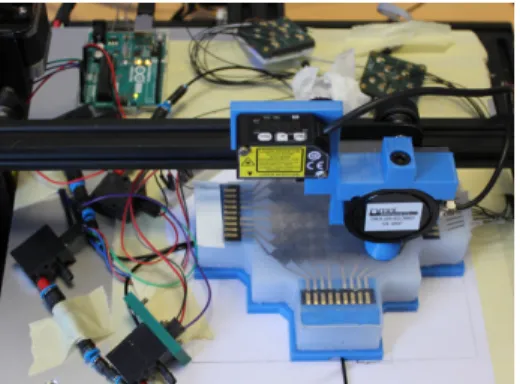
1Abstract— In this paper, we address the challenge of sensor fusion in Soft Robotics for estimating forces and deformations. In the context of intrinsic sensing, we propose the use of a soft capacitive sensor to find a contact’s location, and the use of pneumatic sensing to estimate the force intensity and the deformation. Using a FEM-based numerical approach, we integrate both sensing streams and model two Soft Robotics devices we have conceived. These devices are a Soft Pad and a Soft Finger. We show in an evaluation that external forces on the Soft Pad can be estimated and that the shape of the Soft Finger can be reconstructed.
I. INTRODUCTION
The emergence of Soft Robotics has brought about a new stream of ideas in the domain of sensing. The challenge to sense external forces and the shape of these deformable robots has spawned many new sensor designs and the use of novel sensing principles. Meanwhile, estimating the state of a soft robot based on multi-modal sensing streams is an open challenge. In general, approaches for sensing can be found that use learning-based, analytical and numerical methods.
In this work, we follow up on our previous work on model-based pneumatic sensing [1] and we explore the idea of model-based sensor fusion to address force and shape sensing in Soft Robotics. The central idea of this approach is to use a numerical model, which allows to differentiate the measurement of deformation from what causes it. To this
This work was supported by the Region Hauts-de-France, the project CO-MOROS (ANR-17-ERC2-0029), the European Regional Development Fund (ERDF), ROBOCOP (ANR-19-CE19-0026) and the project Inventor (I-SITE ULNE, le programme d’Investissements d’Avenir, M´etropole Europ´eenne de Lille). It was also supported by the Federal Ministry of Education and Research (Bundesministerium f¨ur Bildung und Forschung, BMBF) within the project (Verbundprojekt-Nr.: 16SV7823K:) and Project of Department of Education of Guangdong Province (No.2019KZDXM037).The authors would like to thank the students Carlos Lagarde, Manuel Sanchez, Florent Chochoy and Pierre Sens for their engineering contributions to this work.
1Authors are with team DEFROST at Inria Lille - Nord Europe and CRIStAL - Centre de Recherche en Informatique Signal et Automatique de
Lille, France, contact:stefan.escaida-navarro@inria.fr
2Author is with Hasselt University, Institute for Materials Research (IMO) 3Author is with IMEC vzw, Division IMOMEC
4Authors are with Institute for Anthropomatics and Robotics - Intelli-gent Process Control and Robotics Lab (IAR-IPR), Karlsruhe Institute of Technology
5Author is with Institute for System Engineering and Systems Design -Robotics Lab, Carinthia University of Applied Sciences
6Author is with the Institute of Smart System Technologies, Sensors and Actuators Department, Alpen-Adria-Universit¨at Klagenfurt
7Author is with the Karlsruhe University of Applied Science 8Author is with Hasselt University, Flanders Make, EDM
Fig. 1: In this work, we present two devices, a Soft Pad and a Soft Finger, that include capacitive and pneumatic sensing. Capacitive sensing allows us to find contact locations and pneumatic sensing to measure the amount of deformation. Sensor fusion is mediated by a numerical model (FEM), which allows us to estimate the forces being applied and the deformation of the devices.
end, we use capacitive and pneumatic sensing. We employ capacitive sensing for detecting the location of external con-tacts and pneumatic sensing for quantifying the deformation. We provide two example devices that display the principles of the proposed approach (see Fig. 1, for dimensions Fig. 5):
• A Soft Pad that has a deformable electrode array embedded in its upper layer and embedded cavities underneath. The electrode array allows the detection of contact location, while the cavities allow for quantify-ing the amount of deformation by measurquantify-ing volume changes. Using both sensing streams and the model, the contact’s location, the contact’s force and the resulting deformation can be estimated.
• A Soft Finger that has electrodes on its segments and pneumatic cavities between its segments. The electrodes allow for detecting contacting objects, while the cavities again allow sensing the amount of deformation. In ad-dition, the finger is actuated by a cable, which can also
be considered by the model. Therefore, the sensing of external contacts can take into account the deformation already caused by the actuation.
For the Soft Pad, we evaluate the performance of the contact location and the force estimation. For the Soft Finger, we show that external contacts can be detected reliably and provide an evaluation for the estimation of the deformation. The results for both platforms are encouraging to further pur-sue this sensor fusion approach. A video accompanying this paper illustrates these approaches and provides additional example interactions to the ones presented here.
The remainder of the paper is structured as follows: In the next section, we review the related work from the field. In Sec. III, we describe the devices we fabricated and how we obtain capacitive and pneumatic measurements respectively. In Sec. IV, we describe our modeling approach and how it allows us to fuse the sensor streams. Then, in Sec. V, we provide an experimental validation using the proposed devices. Finally, in Sec. VI, we summarize our contributions and give a perspective on future research ideas.
II. RELATEDWORK
A variety of measurement principles/physical effects have been shown to work for tactile sensing and shape sensing in deformable materials. Pneumatic sensing is a popular option for tactile sensing. One of its advantages is, that it allows sensing and actuation at the same time, as shown in [2]. The authors implemented a soft pad that can sensorize a robot’s environment and provide cues for grasping by estimating the center-of-mass and orientation of an object, all while having variable stiffness. Our own previous work [1] uses embedded air chambers for detection of location. However, these approaches do not scale very well in terms of the number of sensing points, compared to capacitive sensing, e. g. [3]. This is due to the bulky instruments, valves and tubing involved. One technology that has received significant attention in recent years in sensor designs is using liquid metal, i. e. gallium-indium-tin, Galinstan. The liquid can be embedded in microchannels inside soft structures. Depending on the geometry of the channels, changes in strain or tactile pressure bring about changes in resistance for example [4]. Another significant trend is the development of additively manufactured sensors [5], where the authors show a flexible design inspired by the rigid electrode layouts prevalent in consumer-electronics. In this work, we follow up on [5], but this time we use Galinstan to fabricate deformable capacitive touch-pads, which exhibits great deformability and is therefore better suited for our use-case [6].
Regarding shape sensing, some interest is directed towards optical sensing principles, like Ledermann et al., who have studied the use of optical fibers, e. g. [7]. For shape sensing, even capacitive sensing has been studied recently by Scimeca et al. [8]. The authors propose to use a capacitive tactile array at the base of a soft finger segment, sensing pressure distribution in order to estimate the pose of the tip using a feed-forward neural network trained using visual tracking
data. However, these approaches do not include measuring of external contacts to estimate the resulting deformations.
Works close to our approach in terms of multi-modal sensing are due to Truby et al. [9], Soter et al. [10] and Yang et al. [11]. Truby et al. show a complex sensorization of a soft finger, featuring a bending sensor, an inflation sensor and a contact sensor on the finger-tip. The bending measurement is shown to be independent of the inflation readings, meaning that it is possible, in principle, to estimate the bending radius independently of the pressure used for actuation, for instance, when the finger contacts an object. However, their work only shows results for regressions and does not deal with multiple interactions along different directions. Soter et al. propose a design in which cavities inside a soft pad are filled with a colored liquid [10]. A display showing the level of the liquid in the cavity is used to monitor touch and bending interactions on two different devices. In terms of modeling, the sensor is identified at a single pressure point or bending along one direction through regression. Yang et al. [11] conceive a pneumatic sensor in the shape of a cuboid made out of silicone. They model the deformation of the wall carrying a weight similar to a beam. They find the beam deformation that best explains the pressure through the volume change, which results in the estimation of the force/weight. The same pneumatic sensor is then used to detect curvature by means of a geometric model (not a beam). However, this approach lacks an integration strategy, where shape and force can be estimated using the same model.
In general, a proficient approach for integrating multiple sensor streams is still missing. We propose a method which is entirely model-based, i. e. that does not rely on learning, and that leverages this model to fuse multi-modal sensor streams in order to estimate forces and deformations. Learning can achieve high levels of accuracy, e. g. [8]. However, the feature-space used for learning grows exponentially for each additional sensor added to device. Meanwhile, a model-based approach scales well with the number of sensors, because adding further constraints that represent them in the model is low cost (see Sec. IV). Finally, the presented model-based approach easily adapts to changes in the design of the devices, whereby the learning effort could be wasted upon redesign.
III. SENSING
A. Capacitive Sensing
Two main realizations of capacitive sensing are possible: single-ended or self-capacitive (see Fig. 2 (left)) and mutual-capacitive (see Fig. 2 (right). In single-ended sensors, an AC-voltage is applied to a send-electrode (Tx). This potential is responsible for an electric field that couples into any nearby conductors or objects capable of draining the electric field (such as, e. g., the human body). In the example of Fig. 2, the sensor couples mainly to a human finger, which is considered as a conductor that has an impedance Z to ground. Some of the coupling in this scene is static (in blue) and some is subject to change as the human finger moves. Changes in the
~ E φ1 Tx Ground φ0 Z Ground ~E φ1 φ0 Rx Tx φ00 Z
Fig. 2: Single-ended mode (left): The electrode is driven with an electrical potential and generating an electrical field between the measurement electrode and the object. Mutual-capacitive mode (right): the right electrode transmitter or Tx is driven, generating an electrical field, which ends at receiver or Rx. A conductive object within the measurement range blocks/shields the field lines (green) between the electrodes.
Electrodes
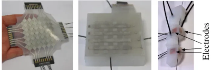
Fig. 3: Left: An array of electrodes made out of Galinstan worked into a deformable silicone sheet. Middle: A 4×4 version of the Soft Pad. Right: A transparent version of the Soft Finger where the size and location of the electrodes is shown.
coupling will be reflected by changes in the amplitude of the measured send current. Static coupling, also called parasitic effects, will cause an offset value. To guide the coupling to a desired region in the sensing area, active-shielding can be employed.
In mutual-capacitive sensors, two kinds of electrodes are connected to the sensing unit, send (Tx) and receive (Rx). Again an AC-voltage is applied to Tx and the potential of Rx is brought close to ground. Therefore, an electrical field is built up between the two electrodes, which is responsible for a displacement current that is usually measured at Rx. In Fig. 2 (right), it is shown that a human finger, being a conductive object with a connection to ground, will drain a certain amount of field lines between Tx and Rx. In this case, the displacement current will drop. This is the so-called shieldingeffect due to the object. The complementary effect, coupling, can be observed in tactile sensing elements where the electrode distance changes due to external forces. The electrodes approaching each other leads to an increase of the displacement current, as described e. g. in [3].
B. Sensing Elements, Electronics and Fabrication
In this work, there are three capacitive sensing elements being used, which are shown in Fig. 3. We have developed an 8×8 pad, a 4×4 pad and the sensors embedded in the Soft
Sensor Module 1
Clk
Capacitive Image
64mm
Sensor Module 2
Fig. 4: Left: The interlocking diamond-pattern in which the electrodes are arranged including overall size information. Right: A capacitive image obtained using single-ended mea-surements when pressing on the Soft Pad as seen in Fig 1.
Finger. The sensitive area of the 8×8 pad has the dimensions of 64×64 mm2 (see Fig. 4). The 8×8 array included in the
Soft Pad and the electrodes inside the Soft Finger are driven in single-ended mode and are used in the main evaluation of the proposed approach. The 4×4 pad is driven in mutual-capacitive-mode to investigate multi-touch. The electronics hardware used for the 8×8 pad and the Soft Finger in the single-ended mode were previously described in [12]. The hardware used for the 4×4 pad in mutual-capacitive mode was previously presented in [13].
The capacitive sensing elements of the Soft Pads use Galinstan liquid metal electrodes encased in silicone rub-ber to allow for great deformability. They are made using an openly accessible, Do-It-Yourself fabrication approach, called Silicone Devices, which does not require any advanced machinery, except for a CO2laser cutter [6]. Circuit
compo-nents (in this case, only connectors) were first fixated on the surface of a silicone sheet. Next, on top of these connectors, a stencil is laser cut in place out of vinyl sticker. Galinstan is then stencil-patterned into a first layer of the interlocking diamond design and subsequently overmolded with silicone rubber. The second layer of the design is then created by repeating the steps. All consumable items can be readily purchased online, as detailed in the fabrication approach’s accompanying Instructable.1
C. Implementing a Capacitive Touch-Pad
In Fig. 4 (left), the schematic of the 8×8-pad is shown. Two capacitive sensor modules with 8 channels each are used to perform the capacitive measurement in single-ended mode. The modules are synchronized with a clock signal to reduce cross-talk effects between them. Every column and row are driven with an AC exciter signal with a frequency around 100 kHz and a peak-to-peak amplitude of 5 V. The corresponding changes in the amplitude due to the presence of an object at the pad is calculated and provided at 100 Hz. In fact, each row and column detects the finger before contact. By applying the outer product to the collected readings scol of the columns and srow of the rows, that is
Img= scol⊗ srow, a capacitive image is generated with the 1https://www.instructables.com/id/Silicone-Devices/
48 49 0 100 20 40 60 80 120 Pad V olumes (uL) 14 13 Time (s) 0 2 -1 1 3 Fing er Pressures (kP a) 150mm 121mm
Fig. 5: Distribution of the cavities inside the Soft Pad and the Soft Finger, example signal values from the deformations seen in Fig. 1 and dimensions of the devices.
resolution of 8 × 8 (see also [5]). Fig. 4 (right) shows the resulting image when a finger touches the pad (see Fig. 1). Further examples are shown in the video attachment. To estimate the location of an external contact, the readings of the columns and the rows are interpolated independently to yield the x and y coordinate respectively, assuming that only one touch event occurs at a time.
D. Pneumatic Sensing
Regarding pneumatic sensing, we use two types of sensors in this work. The time-integrated values of air-flow sensors are used to directly measure the changes in volume of the cavities inside the Soft Pad, as in our previous work [1]. There, we provided a detailed account of the sensing princi-ple including sensitivity, hysteresis and repeatability. Pres-sure sensors are used to meaPres-sure the presPres-sure change in cavities inside the Soft Finger. The structures of the cavities and example signals are shown in Fig. 5. In the case of the Soft Pad, the structure of the cavities is aimed at covering the sensitive area in a uniform way, i. e. approximately uniformly distributed sensitivity with respect to touch. Highly non-uniform sensitivity is more difficult to model, as seen later in Sec. V-A. In the case of the Soft Finger, the cavity shape and distribution are responsible for sensitivity along the two desired bending directions (in the lateral and frontal planes). We arrived at these designs through experience as well as trial and error, but we think that an automated approach could help in finding optimized shapes for the given tasks in the future.
The air-flow sensors used are the D6F-P0001A1 by OM-RON Corp. One great advantage they have is, that they are suitable for a large range of force measurements, as they do not saturate at a certain force level, like a pressure sensor would, while maintaining a high resolution. One of their main weaknesses is a drift-effect that appears over time, which is reflected by the hysteresis [1]. This can be circumvented on the Soft Pad by resetting the integration every time the user releases the finger from the pad. However, this drift can not be dealt with by re-initialization in the case of the Soft Finger. Therefore, we decided to fall back to using the NXP Semiconductors MPX5100 absolute pressure sensors, which have no noticeable drift.
~v3 p3p4 p5 p1 p2 ~v1~v2 ~v4~v5
Fig. 6: In SOFA, actuation forces can be distributed to any number of points on the FEM-mesh.
IV. NUMERICALMODELINGTECHNIQUES
In this section we describe the numerical model that is implemented in our simulation framework SOFA2.
A. Online Finite Element Modeling (FEM)
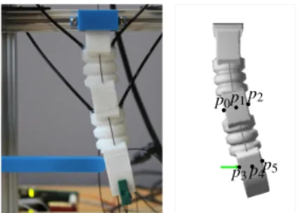
We use the FEM, which yields the internal elastic forces F(q), given that the nodes of the FEM mesh are at positions q (see Fig. 1 right). In SOFA, we use a formulation that accounts for the geometric non-linearities of the deforma-tion and the material is characterized by the Hooke’s law (Young’s modulus and Poisson’s ratio). During each step i of the simulation, a linearization of the internal forces is computed:
F(qi) ≈ F(qi−1) + K(qi−1)dq, (1)
where dq = qi− qi−1 is the displacement of the nodes and
K=∂ F(qi−1)
∂ q is the tangential stiffness matrix for the current
node positions q. To complete the picture, external forces are included:
0 = −K(qi−1)dq + P + F(qi−1) + HTλ . (2) HTλ is a vector that gathers boundary forces, such as
contacts or external controlled inputs, e. g. cable actuators. The size of λ is equal to the number of rows in H and to the number of actuators (contact forces, cables, etc.). P represents known external forces, such as gravity. Then, (2) is solved under the assumption of static equilibrium, delivering a motion that is a succession of quasi static states. Please refer to [14] and [15] for a more in-depth discussion about the FEM formulation used here.
B. External Forces Actuation
In SOFA, it is possible to model external force actuators that simply apply forces on some nodes of the FEM-mesh. In this work, this force actuation is used to represent the pushing on the Soft Pad or the Soft Finger. The actuation magnitude is given by the pressure variable λf, which can be distributed
to a number of points pi on the FEM-mesh, as shown in
Fig. 6. In this work, it is the capacitive sensors that drive the location of the applied force and therefore the selection of the points. Each resulting force ~Fi is determined by the pressure
λf and the 3D distribution ~vi on nodes, i. e. ~Fi= ~viλf. The
distribution is gathered in a row matrix Hf = [..., ~vTi , ...],
so that the expression HTfλf represents the force actuation
in (2).
p5 p4 p3 p2 p1 ppull p6 ~ Fλc dc ~ vi,a pi ~ vi,b ~ vi,c
Fig. 7: Illustration of the modeling of cable actuation in SOFA on the example of a deformable finger (the figure is adapted from [15]).
In modeling the Soft Pad’s indentation, we have set the actuation directions all perpendicular to the sensor surface and distribute the actuation magnitude equally among all affected points in a certain radius, to match the indenter (see Fig. 8). In the example of the Soft Finger, we use up to two force actuators, each one applied to a single point.
C. Cable Actuation
Another one of the actuation modalities available in SOFA are cables. Here we recapitulate on a previous paper [15], where the approach to cable actuation was previously ex-plained. A cable in SOFA is specified by a series of points piwhere the cable is attached to the FEM-mesh, as illustrated
by Fig. 7. A special point defined outside the FEM-mesh is ppull, where the displacement/force is being applied. Here, we illustrate the cable actuation displacement dc as being
applied by a rack and pinion system, like it is actually used in this work. The displacement translates to a force ~Fλc, having a magnitude λc.
As in Sec. IV-B, each point pi is the placement for a
force constraint on the FEM-model. This time, the direction of the constraint is found as the difference between the cable direction after and before pi (see Fig. 7):
~
vi,c= ~vi,a− ~vi,b. (3)
Like before, all the constraints are gathered in the row Hc=
[..., ~vT
i,c, ...], so that the expression HcTλcrepresents the cable
actuation in (2). The total cable length is calculated as
δc(p) = N−1
∑
i=0kpi+1− pik. (4)
D. Transforming Pressure Measurements to Volumes The force and shape estimation method is currently based on volume information as inputs, not pressures. As we are using pressure sensors in the Soft Finger, it is necessary to transform pressures to volumes. For now, we use the assumption that the pressure inside the cavities of the Finger does not significantly affect the shape of the cavity when it is being compressed by the external forces or action of the cable. In other words, we do not currently model the forces due to the pressure inside the pneumatic cavities, which in general could affect their shape. This is, however,
an acceptable simplification for the setup we use, as the measured pressures are in the lower kPa-range (see for example Fig. 5). This way, we use the ideal gas law to transform from pressure readings to volumes:
PV= nRT, (5) where P is the pressure, V the volume, n the number of moles of gas, R the ideal gas constant and T the temperature. We assume furthermore that we have constant temperature, so that the right hand side of (5) is in fact constant. For the initial conditions we get:
P0V0= nRT = C. (6)
Therefore, the relationship between pressure and volume for a measurement is:
∆V = C (P0+ ∆P)
−V0. (7)
E. Finding Forces and Cable Displacement through Opti-mization
Using inverse problem solving [15], we can optimize for the actuation (force, cable) that best explains the volume changes inside the pneumatic sensors of the Soft Pad and Soft Finger (see Sec. III-D). The readings of the Soft Finger are converted according to (7) from the pressure measurement. Let Φi(q) be the function that maps the positions of the
nodes of the FEM-mesh to the volume of a pneumatic cavity with index i ∈ {1, 2, . . . }. Φi(q) can be calculated using the
triangles of the mesh defining the cavity and is already implemented in SOFA.
The actuation forces due to pushing or the cables are given by ∆λ = (∆λf1, . . . , ∆λc1, . . . )T. To find the relation between
the change in applied forces and the change in the (simulated) volume ∆Vi,sim of one pneumatic sensor we can write:
∆Vi,sim=
∂ Φi(q)
∂ q K
−1HT
∆λ . (8) Therefore, first the changes of forces are mapped to the cor-responding nodes through HT, as discussed in Sections IV-B
and IV-C. The tangential compliance matrix K−1transforms these forces to (FEM-)node-displacements, which finally can be mapped to changes in volume through the derivative of Φ with respect to q. For conciseness, we rewrite ∂ Φi(q)
∂ q K
−1HT
as Wi,va, which is the matrix that directly maps changes in
actuation force to changes in volume. Now, we can for-mulate the optimization problem. We want to minimize the difference between the simulated volumes ∆Vi,sim= Wi,va∆λ and the real changes in volume ∆Vreal= (∆V1, . . . , ∆VN)T=
Wva∆λ :
∆λout= arg min ∆λ
kWva∆λ − ∆Vrealk2,
s.t. ∆λmax≥ ∆λ ≥ 0.
(9)
Finally, we write out the squared expression. There, we ignore the constant term corresponding to ∆VrealT ∆Vreal for
the optimization: ∆λout= arg min
∆λ
Fig. 8: Experimental setup for the Soft Pad.
Fig. 9: Distribution of the estimated contact locations for all data points.
This quadratic program (QP) is solved using a QP-solver with the method presented in [15]. If the force is applied by a cable, once we have found ∆λout and applied it to the
model, we can simply use (4) to find the corresponding cable lengths δc, which in turn gives us the displacements dc.
In summary, this modeling approach allows to seamlessly integrate the information from the capacitive sensors (push-ing location), the information from the pneumatic sensors (amount of deformation) as well as cable actuation to re-construct the force acting on deformable structures. The numerical model mediates the sensor fusion. Beyond that, an estimation of the deformed shape is obtained.
V. EVALUATION
A. Soft Pad
To evaluate the performances of the presented approach, we have performed an experiment designed to test the accuracy of the localization and force reconstruction (see Fig. 8). To this end, the Soft Pad was sampled in a regular grid of 10×10 (100 times) in three different force levels: ∼5 N, ∼10 N and ∼15 N. The diameter of the indenter is 20 mm.
1) Localization Accuracy: Fig. 9 shows the estimated and ground truth location of each contact during the sampling procedure. The samples are organized by the Force Level (1-3) with a marker at the estimated position. Overall, all
Pos. Error (mm) Pos. Error (%) Force Level mean (mm) std (mm) mean (%) std (%)
1 (∼5 N) 1.06 0.77 1.67 1.20 2 (∼10 N) 1.16 0.76 1.81 1.19 3 (∼15 N) 1.02 0.70 1.59 1.09 All 1.08 0.75 1.68 1.17 TABLE I: Positioning error for the capacitive array
Force Error (%) Set mean std All 10.89 11.00 Circular Worspace 7.79 5.24 CW FL 1 9.40 5.50 CW FL 2 6.42 4.77 CW FL 3 7.56 6.40
TABLE II: Force reconstruction error for Soft Pad
estimated positions fall within close proximity to the ground truth position. The largest systematic deviations are on the border of the array. That is: points are estimated to lie further inside the array than their actual position. Since the location is estimated as an average of neighboring signal values, this is natural, as there are no measurements past the outside of the array to compensate for that bias.
Table I shows the summary of the statistics pertaining the localization accuracy. The overall accuracy, as shown in the last row, is 1.08 mm ± 0.75 mm. This value being around a 3% error is a satisfactory performance. What is interesting for us to observe is, that the localization is mostly insensitive to the amount of force applied (Force Levels 1-3). Even if the pad is deformed, the localization performance remains unchanged, which is a desirable property. For the future, further analysis in other deformation regimes, such as stretching, will be interesting. Overall, we think that the overall performance can be improved by adapting the measurement electronics further to this use case.
2) Force Estimation: The overall results of the force reconstruction are summarized in Table II. Considering all data points, the reconstruction error is 10.89 % ± 11.00 %. This value can be considered to be somewhat coarse. As illustrated by Fig. 10a, which shows the data points for Force Level 1, the estimation deviates most from the ground truth on the corners of the array. Selecting a circular workspace of radius r = 28 on the pad (the side length to the array is 56 = 2 · 28), i. e. avoiding the corners, decreases the reconstruction error to 7.79 % ± 5.24 %. The area covered is still more than 75% and this is a more satisfactory value estimation error, as it would be challenging to radically improve upon them. Two main causes were identified for the remaining errors. First, there is the dramatic difference in measured volume on the corners compared to the rest of the array, even though similar forces are applied. Second, there is a non-symmetric behavior of the material, even though the applied forces are uniform. Regarding the first type of error: while the simulation can account for changes in stiffness, it remains difficult to represent bigger changes correctly, such as on the corner of the array. This is especially true for our simulation,
(a) Estimated vs. real forces over the whole area of the array (Force Level 1)
(b) Volume distribution for Force Level 1 over the whole area of the array
(c) Estimated vs. real forces in a circular subset of the area of the array
(d) Volume distribution for Force Level 1 over the circular subset of the array
Fig. 10: Plots showing the detail of data points from Force Level 1 regarding the error of force estimation and the total volume measured at each point. Ground truth force measurements are shown in blue, estimated forces in red.
because for real-time performance only a limited number of elements can be used. Regarding the lack of symmetry in the volume measurements: it indicates that there might be an inconsistency in the fabrication of the silicone structure. The fabrication process of this structure at this scale is challenging, but we think it is possible to improve this behavior. All things considered, we believe that these results are encouraging for this kind of approach, as both types of problems discussed can be addressed.
3) Considerations on Multi-Touch : The measurement results with the 4×4 Soft Pad and mutual-capacitive read-out are illustrated for one electrode in Fig. 11. There, the sensitivity to proximity and force as well as the multi-touch capabilities are shown: In part one, the finger is approaching the pad and then touching it. This leads to a signal decrease due to the shielding effect of the finger (see Sec. III-A). Then, force is applied in part two and the signal increases again. In this situation, the gap between the electrode layers becomes smaller due to the force and thus we see a strong coupling effect. In other words, this configuration is different than the self-capacitive measurements, because the measurements exhibit both sensitivity to proximity and force. Thus, in part three, we see a signal increase due to the compression of a neighbouring (the third) electrode. Due to the low modulus of elasticity of the silicone, this compression force is seen on the first electrode as well, but less strongly. In part
four, there is a another touch event as part of a multi-touch configuration. The blue matrix plot in the lower part of the figure illustrates the detection of touch points. Overall, these results indicate that measurements in the mutual-capacitive mode are a promising future approach for detecting contact location including multi-touch as well as providing force related readings, similar to traditional tactile sensors [3], [8].
Section 1 Section 2 Section 3 Section 4 slow touch force applied force on
3rd electrode touch on 3rd electrodes1st and
multitouch
Fig. 11: Signal evolution for various touch and force events on one electrode of the 4×4 pad.
B. Soft Finger
In this evaluation, we cover two aspects of the performance of the Soft Finger. The first one is with respect to the ability to detect one or more contacts by means of the capacitive sensors and the second one is with respect to the estimation of the shape.
1) Contact Detection: To detect a contact, a simple threshold is applied to the signal of the capacitive sensors. Then, the constraints corresponding to the contact are en-abled in the model (see Sec. IV-B). The model will find the amount of force applied to all enabled constraints, including cable actuation, that best explains the measured changes in deformation (volume). The amount of force found for a contact is not determined by the intensity of the capacitive sensor value, but by the optimization method. In Fig. 12, the case of two simultaneous contacts is shown. The signals corresponding to the enabled contacts is clearly distinct from the not activated contacts. It is not necessary to fine-tune this threshold to get satisfactory behavior for conductive objects, such as the human finger. However, detection of non-conductive objects remains a challenge for this setup. A mutual-capacitive design could address these use cases. For a more thorough display of possible interactions, please see the attached video.
2) Shape Estimation: To test the accuracy of the shape reconstruction, the lateral-tip shown in Fig. 13 was used. It is attached to the test-bed displayed in Fig. 8. The finger is pushed separately on the points p0 and p3 by 5, 10,
15 and 20 mm respectively. The estimated displacement of p0 and p3 in SOFA is compared to the real displacement.
This experiment is performed with the finger starting from its rest position as well as with the finger initially actuated
12 13 14 15 0 200 -100 300 Time (s) S ig na l A m pl itu de 100
Fig. 12: Two contacts are detected simultaneously on the finger.
p0p1p2
p3p4p5
Fig. 13: The finger is pushed by a lateral-tip on p3 and the
pose is reconstructed in SOFA.
by the cable, which is pulled by a distance of 10 mm. In this scenario, SOFA uses both the cable actuation and the contacts to estimate the pose of the finger (see also attached video). The results are summarized in Table III. Overall, the estimation error is 1.26 mm ± 0.85 mm, or about 15 %, which should be already useful in many applications. In this setup, we have explored smaller deformations surrounding the initial pose of the finger. While the positioning accuracy of the test-bed is better than pa= 0.1 mm, the pushing leads
to a pivoting of the finger over the lateral-tip. This pivoting can be neglected for small displacements, but limits its use for larger ones. Overall, to investigate larger deformations, we will improve our test-bench, for example by using optical tracking.
VI. CONCLUSIONS
In this work, we have shown a model-based approach to combine capacitive sensing with pneumatic sensing to detect and model touch in deformable structures. The numerical model allows exploiting the strength of each measurement principle. Capacitive sensing is used to detect contact loca-tions and pneumatic sensing is used to detect the amount of deformation resulting from the touch interaction. We evaluate this approach on two devices, a Soft Pad and a
Point Cable Error (mm) Error (%) Actuation (mm) mean std mean std p0 0 1.93 0.64 16.45 2.43
p0 10 0.55 0.24 6.69 5.20
p3 0 1.12 0.67 8.00 2.31
p3 10 1.42 0.99 9.51 4.48
All 0 and 10 1.26 0.85 10.16 5.36 TABLE III: Displacement tests for the finger
Soft Finger. Our results indicate that this approach is a promising alternative for the challenge of sensor fusion in Soft Robotics. In the example of the Soft Finger, we even show that our approach can handle pre-deformations due to cable actuation.
One of the big limitations regarding the capacitive sensing we know of is that we could not show the implementation of high-resolution, multi-touch events. By dedicating more effort to the mutual-capacitive sensing modality, we will address this in the near future. Furthermore, we would like to explore the application of our concept to more elaborate Soft Robotics designs, such as a hand or a trunk-robot for inspection tasks having redundant actuation.
REFERENCES
[1] S. Escaida Navarro, O. Goury, G. Zheng, T. M. Bieze, and C. Duriez, “Modeling novel soft mechanosensors based on air-flow measure-ments,” IEEE Robotics and Automation Letters, vol. 4, no. 4, pp. 4338–4345, 2019.
[2] C. Gaudeni, M. Pozzi, Z. Iqbal, M. Malvezzi, and D. Prattichizzo, “Grasping with the softpad, a soft sensorized surface for exploiting environmental constraints with rigid grippers,” IEEE Robotics and Automation Letters, vol. 5, no. 3, pp. 3884–3891, 2020.
[3] P. Maiolino, M. Maggiali, G. Cannata, G. Metta, and L. Natale, “A flexible and robust large scale capacitive tactile system for robots,” IEEE Sensors Journal, vol. 13, no. 10, pp. 3910–3917, 2013. [4] Y.-L. Park, B.-R. Chen, and R. J. Wood, “Design and fabrication of soft
artificial skin using embedded microchannels and liquid conductors,” IEEE Sensors Journal, vol. 12, no. 8, pp. 2711–2718, 2012. [5] L.-M. Faller, S. M¨uhlbacher-Karrer, and H. Zangl, “Inkjet-printing
rapid prototyping of a robust and flexible capacitive touch panel,” in IEEE Sensors 2016, 2016.
[6] S. Nagels, R. Ramakers, K. Luyten, and W. Deferme, “Silicone devices: A scalable diy approach for fabricating self-contained multi-layered soft circuits using microfluidics,” in Proceedings of the 2018 CHI Conference on Human Factors in Computing Systems, ser. CHI ’18. New York, NY, USA: Association for Computing Machinery, 2018. [Online]. Available: https://doi.org/10.1145/3173574.3173762 [7] C. Ledermann, J. Mintenbeck, Y. Ding, H. Pauer, and H. W¨orn,
“Closed-loop control of a flexible instrument using an integrated fbg-based shape sensor,” in International Conference on Advanced Technology & Sciences (ICAT’15), 2015.
[8] L. Scimeca, J. Hughes, P. Maiolino, and F. Iida, “Model-free soft-structure reconstruction for proprioception using tactile arrays,” IEEE Robotics and Automation Letters, vol. 4, no. 3, pp. 2479–2484, 2019. [9] R. L. Truby, M. Wehner, A. K. Grosskopf, D. M. Vogt, S. G. Uzel, R. J. Wood, and J. A. Lewis, “Soft somatosensitive actuators via embedded 3d printing,” Advanced Materials, vol. 30, no. 15, p. 1706383, 2018. [10] G. Soter, M. Garrad, A. T. Conn, H. Hauser, and J. Rossiter, “Skinflow: A soft robotic skin based on fluidic transmission,” in 2019 2nd IEEE International Conference on Soft Robotics (RoboSoft). IEEE, 2019, pp. 355–360.
[11] H. Yang, Y. Chen, Y. Sun, and L. Hao, “A novel pneumatic soft sensor for measuring contact force and curvature of a soft gripper,” Sensors and Actuators A: Physical, vol. 266, pp. 318–327, 2017.
[12] H. Alagi, S. E. Navarro, M. Mende, and B. Hein, “A versatile and modular capacitive tactile proximity sensor,” in 2016 IEEE Haptics Symposium (HAPTICS), Apr. 2016, pp. 290–296.
[13] L.-M. Faller, T. Mitterer, J. P. Leitzke, and H. Zangl, “Design and Eval-uation of a Fast, High-Resolution Sensor EvalEval-uation Platform applied to MEMS Position Sensing,” IEEE Transactions on Instrumentation and Measurement, vol. 67, no. 5, pp. 1014–1027, 2017.
[14] C. Duriez, “Control of elastic soft robots based on real-time finite element method,” in Robotics and Automation (ICRA), 2013 IEEE International Conference on. IEEE, 2013, pp. 3982–3987. [15] E. Coevoet, T. Morales-Bieze, F. Largilliere, Z. Zhang, M. Thieffry,
M. Sanz-Lopez, B. Carrez, D. Marchal, O. Goury, J. Dequidt et al., “Software toolkit for modeling, simulation, and control of soft robots,” Advanced Robotics, vol. 31, no. 22, pp. 1208–1224, 2017.


![Fig. 7: Illustration of the modeling of cable actuation in SOFA on the example of a deformable finger (the figure is adapted from [15]).](https://thumb-eu.123doks.com/thumbv2/123doknet/14431001.515173/6.918.117.413.75.232/illustration-modeling-actuation-example-deformable-finger-figure-adapted.webp)