Design of an Automated Sorting and Orienting
Machine for Electronic Pins
by
Michelle Sueway Chang
S.B. Massachusetts Institute of Technology (2011)
Submitted to the Department of Mechanical Engineering
in partial fulfillment of the requirements for the degree of
Master of Engineering in Manufacturing
at the
MASSACHUSETTS INSTITUTE OF TECHNOLOGY
September 2012
@
Michelle Sueway Chang, MMXII. All rights reserved.
The author hereby grants to MIT permission to reproduce and to
distribute publicly paper and electronic copies of this thesis document
in whole or in part in any medium now known or hereafter created.
Author ...
Certified by...
Depar
of Mechanical Engine ring
23 Au
12
...
-~1
-David E. Hardt
Ralph E. and Eloise F. Cross Professor of Mechanical Engineering
Thesis Supervisor
II ~Accepted by.
V1
David E. Hardt
Chairman, Department Committee on Graduate Studies
Design of an Automated Sorting and Orienting Machine for
Electronic Pins
by
Michelle Sueway Chang
Submitted to the Department of Mechanical Engineering on 23 August 2012, in partial fulfillment of the
requirements for the degree of Master of Engineering in Manufacturing
Abstract
At the power electronics manufacturer SynQor, the printed circuit board (PCB) as-sembly line is fully automated with the exception of the step which inserts electronic pins into the PCBs. Past attempts to automate this process have resulted in two unreliable machines that are not in use on the production line. Thus, electronic pin insertion is currently a manual process.
The design proposed in this thesis for an automated pin insertion system separates the sorting and orienting of the pin from the insertion of the pin into a PCB. This system decoupling allows for more reliable pin delivery, which can in turn increase the insertion speed and reliability. This thesis focuses on sorting and orienting of the pin.
The resulting design takes pins from a bulk state to an oriented state and inserts them in a pin holding magazine. Preliminary trials of the system show promise as an efficient way of preparing oriented pins for use by a pin insertion mechanism, but more experimentation is needed to test the robustness and speed of the sorting system. Thesis Supervisor: David E. Hardt
Acknowledgments
The production of this thesis arose from the contributions of multiple people, directly and indirectly, that I have interacted with during my time in the M.Eng Manufactur-ing program. Of course, the most constant source of feedback was from my teammates Daniel Cook and Rejin Isaac. You were both there every day of this project, and I thank you for inspiring me with your own work ethic.
The employees of SynQor, especially our mentor Lennart Pitzele, were instrumen-tal in helping the team understand the project background and providing support for all aspects of our work. Thank you for your continual understanding despite my not always having a clear path. I wish the company the best in its future and hope that my work has helped in someway.
To my advisor Prof. Hardt, thank you for your patience and your guidance. Each meeting with you motivated me to continually evaluate what I have done and could go on to do.
I would also like to thank Jennifer Craig for her help and encouragement in the thesis process. Your support was doubly meaningful in this process for me in
over-coming my writer's block.
Thanks to GQIE for your steady stream of e-mail updates; to Lihua Bai for her unfailing moral support and thoughts on life; to Steve Voinea and Dan Kolobrubetz for weekly caffeine breaks and helping with the heavy lifting; and finally to my parents and sister for their love and support in what has been a difficult year.
Contents
List of Figures 11
List of Tables 13
1 Introduction 15
1.1 Background & Motivation . . . . 15
1.2 Objectives . . . . 16 1.3 Project Scope . . . .. 17 1.4 Work Distribution. . . . .. 17 1.5 Thesis Structure. . . . . 17 2 System Overview 19 2.1 The Pins. ... .. . . . . . .. .. .. . . . . .. .. ... . . . 19 2.1.1 Electronic Leads . . . . 20
2.1.2 Project Pin Specifications . . . . 20
2.2 Existing Pinning System . . . . 21
2.2.1 Manual Pinning . . . . 21
2.2.2 Automated Pinning System I . . . . 22
2.2.3 Automated Pinning System II . . . . 24
2.3 Developed Solution . . . . 25
2.3.1 Pinning Design Overview . . . . 26
2.3.2 Sorting . . . . 27
2.3.4 System Components . . . .
3 Manufacturing Automation 3.1 Defining Automation . . .
3.2 A Brief History . . . . 3.2.1 Process Controls...
3.2.2 Control and Positioning
3.3 Industrial Robots ...
3.3.1 Robotic Coordinate Systems
3.3.2 Programming Robots . 3.3.3 End Effectors . . . . 3.3.4 Robotic Advances . . . . 3.4 Machine Vision . . . . 3.4.1 Vision Hardware . . . . 3.4.2 Vision Software . . . . 3.5 PCB Automation Technology . . . 3.5.1 Surface Mount Technology
3.5.2 Through-Hole Technology 4 Assembly Systems & Part Handling
4.1 Designing Assembly Systems .
4.2 Carrier Mechanisms . . . . 4.2.1 Continuous Transfer . 4.2.2 Intermittent Transfer . 4.3 Parts Handling . . . ... . . 4.3.1 4.3.2
Feeding and Orienting Mechanisms Feeding Tracks . . . .
5 Sorting System Design
5.1 Design Methodology . . . . 5.2 System Overview . . . . 29 . . . . 29 30 30 31 32 33 34 34 35 36 36 36 37 37 38 39 . . . . 39 . . . . 40 . . . . 40 . . . . 4 1 . . . . 42 42 47 49 49 51 28
5.2.1 Rotary System . . .
5.2.2 Main Frame . . . .
5.2.3 Constraining the Pin .
5.3 Main Rotary Wheel . . . . 5.3.1 Pneumatic Handling .
5.3.2 Rotary Mechanism . .
5.4 Feeding . . . . 5.4.1 Bowl Feeders . . . . 5.4.2 Feeding Attachment Design 5.4.3 Bridge to Wheel . . . . 5.5 Reorientation . . . . 5.5.1 Orientation Determination 5.5.2 Reorientation Mechanism 5.6 Delivery . . . . 5.6.1 Pin Magazine . . . . 5.6.2 Delivery Slide . . . .
6 Sorting Machine Performance 6.1 Evaluation Methods . . . . 6.2 Component Performance . . . . 6.2.1 Bowl Feeding . . . . 6.2.2 Reorientation . . . . 6.2.3 Delivery . . . . 6.2.4 Wheel Indexing...
6.3 Process Independent Problems .
6.3.1 6.3.2 6.3.3
Fabrication Imperfections . . . . .
Pneumatic Pressure and Sensitivity
Burrs & Dents . . . .
6.3.4 Difficult Positioning . . . . 67 . . . . 67 67 68 70 71 71 72 72 72 73 . . . . 7 4 . . . . 52 53 54 55 56 57 58 59 59 60 61 61 61 63 64 64 . .
7 Conclusions, Recommendations, & Future Work
7.1 Conclusions . . . .
7.2 Recommendations . . . . .. . . . . 7.3 Future Work . . . . A Engineering Drawings
A.1 Wheel Assembly . . . . .
A.2 Feeding Assembly . . . .
A.3 Reorientation Assembly
A.4 Delivery Assembly . . .
B Bill of Materials Bibliography 75 75 76 76 79 79 81 85 87 91 93 . . . . . . . . . . . . . . . .
List of Figures
1-1 A power conversion device
Electronic Pin . . . . Arbor press . . . .
Automated Pinning 1 - Sorting System . Automated Pinning 1 - Insertion System
Automated Pinning 2 . . . . Pinning System Process . . . . Pin magazine . . . .
3-1 SCARA and articulated arm robot configurations . . . . 3-2 Gantry robot configuration . . . . 3-3 Adept Quattro . . . .
3-4 The two main methods of securing electronic components to PCBs . Examples of indexing carrier mechanisms . . . .
A reciprocating tube hopper feeder . . . . A generalized representation of a vibratory bowl feeder . . A few types of mechanical traps used commonly in vibratory
The two types of gravity tracks . . . . Photograph of complete sorting system . . . . Layout of sorting system around the rotary wheel . . . . .
CAD drawing of sorting system . . . .
bowl feeders 2-1 2-2 2-3 2-4 2-5 2-6 2-7 . . . . . 16 . . . . 2 1 . . . . 2 2 . . . . 2 3 . . . . 24 . . . . 2 5 . . . . 2 6 . . . . 2 7 33 33 35 38 41 43 45 46 48 50 53 54 4-1 4-2 4-3 4-4 4-5 5-1 5-2 5-3
5-4 Common constraint profile
5-5 Wheel assembly . . . . 56
5-6 Main wheel ... 57
5-7 Feeding assembly . . . . 58
5-8 Bowl feeder attachment . . . . 60
5-9 Photograph of the vision system camera . . . . 61
5-10 Reorientation assembly . . . . 62
5-11 Reorientation flow chart . . . . 63
5-12 Reorientation head detail . . . . 63
5-13 Pin magazine . . . . 64
5-14 Delivery slide assembly . . . . 65
5-15 Delivery slide cross-section . . . . 65 55
List of Tables
Chapter 1
Introduction
1.1
Background & Motivation
The electronics manufacturer SynQor produces power conversion devices, which con-sist of one or more printed circuit boards with specially designed circuits of electronic components. Much of the manufacturing assembly for these devices is automated, but the insertion of electronic pins into the printed circuit boards (PCBs) is still done manually.
Automated processes are desirable as, in most cases, they lower manual labor re-quirements and increase through-put, while also maintaining a high level of accuracy. SynQor has used a number of customized pin insertion machines for the task of in-serting electronic pins. As there are a number of pin types and PCB configurations to accommodate, the previous machines were all are too unreliable or too inflexible
to complete the pin insertion fully automatically.
This project addressed that void with the goal of designing an automated pin insertion system, which would complete the automation of SynQor's PCB assembly process. This thesis in particular concerns itself with the sorting and orienting of electronic pins.
Figure 1-1: A SynQor power conversion device, with electronic pins visible at bottom of board [1]
1.2
Objectives
The project proposed to re-engineer a pre-existing pin insertion system into a produc-tion system that is robust, cost effective, and flexible enough to accommodate future pin variations. The key objectives were as follows:
" Develop a system which reliably sorts, orients, and inserts pins from a loose
bulk state into the PCBs
" Reach a target machine rate of inserting 8 pins in 10 seconds
" Produce a system that is robust while remaining easy to repair and maintain
" Design flexibility into the machine for use with future product lines
" Integrate the machine with the company's centralized tracking system to enable
1.3
Project Scope
Given the short project time frame, this project was limited to designing, building, and testing a prototype of an automated pin insertion system. Though there are many electronic pins in use at the company, the focus here was on designing a system that could effectively insert the company's most commonly used pin type (discussed in Section 2.1.2), while including the flexibility to adapt to other pin types. Though the system was not tested on the main automation line during the duration of this project, the lab bench implementation produced a design and recommendations for
a robust future implementation.
1.4
Work Distribution
The system was divided into three tasks: (1) Sorting the pins from the bulk to an oriented state; (2) inserting the oriented pin into the PCB; and (3) developing the vision and control systems necessary for the two previous tasks. The initial development of each task was done as a group, but further work was split among the group members. This thesis focuses on the sorting of the pins from bulk to oriented state.
Daniel Cook worked on the insertion of the pin into the PCB, and Rejin Isaac was the lead for the vision and control system development. More detailed information about the pin insertion and control system can be found in Cook and Isaac's theses respectively. [2,3]
1.5
Thesis Structure
This thesis consists of four parts, as listed below:
1. The problem and group project: Chapters 1,2
3. Machine design: Chapter 5
4. Critical review of work: Chapters 6,7
Part 1 - This part introduces the problem generally. The project objectives are discussed in Chapter 1, and the group's approach is outlined in Chapter 2.
Part 2 - Background literature is given in this part to position the thesis work here in relation to the greater field of automation. The background review also gives context to the proposed designs in Chapters 2 and 5.
Part 3 - This part describes the thesis author's design methodology and details the sorting system machine design.
Part
4
- The design detailed in Part 3 is reviewed in this part. Preliminary experimental results are presented, and further work and recommendations are sug-gested.Chapter 2
System Overview
The current method of inserting electronic pins into printed circuit boards (PCBs) at SynQor is a mix of automated and manual processes. Though automated machinery exists to complete the task, it has proven to be unreliable, often requiring human monitoring and manual adjustments to complete their tasks. The work presented here is a system designed to overcome the previous systems' shortcomings and allow SynQor to completely automate their assembly line.
Section 2.2 discusses the current machinery present for inserting pins into PCBs, a process which is referred to as "pinning", at SynQor. Some of the requirements for an improved process are apparent in the discussion of the current systems' weaknesses. The group design overview is also described in this chapter. The overall design con-cept and a generalized group solution, along with requirements beyond functional considerations, are presented in Section 2.3.
2.1
The Pins
The main focus of this project is a specialized electronic pin used by the electronics manufacturer SynQor in the majority of its products. At its most basic, an electronic pin is a cylindrical rod of metal designed to carry current from one circuit board to another. Here, the basic function of electronic pins and the specifics of the pin involved in this project are discussed.
2.1.1
Electronic Leads
Pins are a type of terminal component - an electronic lead specific to PCB produc-tion. They are attached to the boards with through-hole technology. By making the connection through-hole rather than surface-mount, the pins can transfer an electronic signal through the thickness of the circuit board, useful for making interconnects on a multilayer board [4].
These pins are mostly used as interconnects between PCBs and other electronics external to the board they are mounted on. While one end of the pin is attached to the PCB, the other end may interface directly with the through holes of another circuit board or with receptacle terminals on another PCB or more flexible leads [4].
2.1.2
Project Pin Specifications
The pins involved in this project are two-sided, cylindrical rods with a collar near the center of the length. The insertion end of the pin is characterized by a square or hexagonal insertion head cross-section. The opposite end interfaces with the end users terminal connections. The length of the pin on either side of the collar is variable, and the total length of these pins ranges from about 0.3 inches to 0.5 inches.
The company uses three diameters of pins, which are 0.040 in., 0.062 in., and
0.080 in.. This project only looks at the most commonly used pin diameter of 0.040
inches. At this pin diameter, the insertion head is a square. The collar on these pins is 0.080 inches in diameter 0.040 inches in length. The only exception is a pin with a 0.060 inch collar length, intended to offset the symmetry of the insertion-end and interface-end lengths. Figure 2-1 is a drawing of the most common pin configuration used in SynQor assemblies.
The pin is attached to the board in a two-step process. First, the pin is inserted into a PCB with a small force fit from the non-circular insertion head. Secondly, the pin is soldered to the board. This project only concerns the first part of pin
attachment - pin to board insertion - as soldering is a well automated process.
S<.040
Figure 2-1: The most common electronic pin used at SynQor
of on the pin collars, which prevent solder cavities from forming during the soldering process. The pins are lead free and made of tin-plated copper. They are manufactured on screw machines and delivered in bulk.
2.2
Existing Pinning System
There are currently three methods for inserting pins into PCB boards, also know as "pinning", at SynQor. The most basic of the methods, manual pinning, relies on an operator to manipulate the pin and insert it into the board. The other two methods are different automated processes. The three processes and their inefficiencies are described in this section.
2.2.1
Manual Pinning
Manual pinning relies on operators to manipulate the pins. An arbor press with a special collet designed to hold a pin using vacuum pressure is used to press the pin into the PCB (Figure 2-2). To set up the process, the operator sets the pin insertion depth of the press by adjusting a hard stop and testing the resulting insertion depth. Once the desired depth is achieved, the operator locks the stop in place. This depth changes as the pin lengths vary, requiring numerous setup changes. The collets are
specific to pin diameter, so a change in pin diameter also requires a setup change. To insert pins in a circuit board, operators rely on drawings that show where and
Figure 2-2: Arbor press used in manual pin insertion process
which pins are to be located on the PCBs. The operator takes a pin from a bulk box of pins and inserts the head of the pin into the collet, where the vacuum pressure holds the pin in place. The circuit board is positioned under the press, relying on the operator to visually align the pin end and the board through holes. The pin is
then pressed into the board, and the process repeats. Once the board is completely populated with its required pins, it is moved into a queue for the next process.
The operators scan each board, and also the boxes of bulk pins being used, into the SynQor tracking system when pinning. This provides some level of part traceability, but is prone to errors as there are often multiple boxes of pins in use by the operators Currently, the manual pinning process requires two to three full time operators, for two shifts per day, to match the work output of the SMT automation line.
2.2.2
Automated Pinning System I
SynQor worked with a custom automation solutions company in the early 2000s to design a pinning machine for integrated us on their assembly line. The idea was to develop a system that could handle multiple pin types automatically. The bulk pins
would be loaded into the system by the operator; but the system would sort, orient, and insert the required pins automatically based on the PCB that is scanned in the machine.
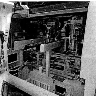
The developed system consists of two units, the bowl table (Figure 2-3) and the insertion machine(Figure 2-4) , connected by a pneumatic air tube through which pins travel. The bowl table is a collection of multiple vibratory bowl feeders to allow the machine to accept a number of pins. The bowl feeders feed the pins onto a conveyor belt. The conveyor transports the pins, with their axis along the direction of motion, past a line-scan camera, and a full image of the pin is developed from the cross-sections that the camera takes. From this image, the pin is analyzed to determine its type and orientation. If the pin is an incorrect type, it is blown off the conveyor belt and sent back to the bowl. Downstream from the camera, an arm picks up the correct pin and orients it, then blows it through the tube to the second unit, the insertion machine.
Figure 2-3: The automated pinning system sorting unit
In the insertion machine, the pin drops into a shuttle that is accessible to the insertion machine's robotic arm. This arm picks up the pin, using vacuum, and positions it at the correct point over the PCB. The machine then presses the pin to the correct depth. The positioning system (a dual-gantry Cartesian robot) on this machine is highly accurate, and part of the team's design relies on the use of this
section of the machine.
Figure 2-4: The inside of the automate pinning system's insertion unit
This machine was used in production briefly but was found to be very prone to failures. Mainly, the bowl table unit could not deliver pins reliably to the insertion machine. Pins would jam at multiple points in the system, such as in the tube that delivered pins from the sorting mechanism to the insertion robot. The sorting mechanism could not identify and orient pins fast enough to keep up with the pace of demand expected by the insertion robot. Often, the insertion machine sat idle while it waited for a pin to be sent from the bowl table.
2.2.3
Automated Pinning System II
The second automated pinning system present at SynQor was purchased from a
com-pany that specializes in odd-from parts placement. It is presented in Figure 2-5. This system employs specially designed vibratory bowl feeders to feed and orient the pins. The bowl feeders are highly customized to accept and sort only a single pin type per vibratory feeder. That is, each feeder is tuned to work with a single pin type. The vibratory feeder designs take advantage of the non-symmetric nature of the pins and employs traps which reject pins that are the wrong size and length, doing so with a fair amount of accuracy.
Once the feeders sort and orient the pins, they are queued in a slide which leads to an escapement. The escapement shuttle picks off one pin from the queue of pins and drops it down a short tube to the insertion head. The board is positioned under the insertion head and a pin is driven to the desired depth. Note that unlike in the first system (Section 2.2.2), here, the insertion head is fixed and the board is moved for positioning.
Figure 2-5: The second automated pinning system. Notice the bowl feeders sitting on top of the machine.
This system suffers from frequent jamming in the bowl feeder to escapement area of the process. Since the bowl feeder is vibrating, pins are constantly being driven forward, pushing against each other in the queue. This can cause the line of pins to jam as pins can ride up on each other, requiring operator intervention to clear the jam. Additionally, The positioning system in this machine has very little in terms of
feedback to know if it has pressed a pin correctly.
2.3
Developed Solution
Based on the past systems and knowledge of machine design, the team designed its own system for inserting pins into printed circuit boards. An overview of the system
is given in this section.
2.3.1
Pinning Design Overview
The pinning process consists of two sub-processes: sorting and insertion. In past at-tempts to automate pinning, the process was run as one series of tasks to be completed in sequence. A failure at one point meant a stop in the whole system. Therefore, the team decoupled the process into two parts to alleviate some of the bottlenecking issues. Bowl SORTING feeding Sorting wheel Rejection Reorientation Magaine Magazine INSERTION feeding Insertion Positioning mechanism robot
Figure 2-6: The process of pinning a PCB is broken into two parts - sorting and
insertion - that are interfaced with a magazine.
The system was decoupled in between the sorting and insertion sub-processes by using a magazine as an interface. The magazine used here would hold a determined quantity of pins in an oriented state for quick dispensing in the insertion process.
Figure 2-7: The pin magazine used to decouple the sorting and inserting processes
[2]
2.3.2
Sorting
The process of sorting pins takes the pins from the bulk delivery state and aligns them in the pin magazine. The sorting process utilizes vibratory bowl feeders to initially feed and orient the pins. They are then transported onto a rotating wheel that has a few stages for process steps. The wheel presents the pins to a camera for vision analysis. This determines what orientation the pin is in and if it it is the desired pin. As the wheel indexes to each station, the pin passes a reorientation stage, which adjusts the orientation on those pins that need it, and the magazine delivery stage, where correctly oriented pins are inserted into the magazine. Pins that are determined to be of incorrect type are dropped into a separate holding spot.
This sorting process can be completed off of the production line, as it does not need to be run serially with the insertion process. When boxes of pins arrive at
SynQor, operators can run the pins through the sorting machine to transfer them to a magazine so there are always magazines ready for the production floor.
2.3.3
Insertion
The insertion process re-purposes the insertion unit mentioned in Section 2.2.2. As previously mentioned, the insertion machine consists of two gantry-style Cartesian positioning robots. Attached to each carriage on the robots are two insertion mecha-nisms. One gantry has an insertion mechanism for 0.040 inch diameter and 0.062 inch diameter pins, and the other has a mechanism for 0.040 inch diameter and 0.080 inch diameter pins. As the 0.040 inch pins are used in the highest volume at SynQor, there are two insertion heads, one on each gantry, to handle and insert them, balancing the workload between the two gantries.
The insertion mechanism utilizes a feed shuttle integrated into the magazine body to dispense pins from the bottom of the magazine. The dispensed pin is sent into an insertion tube that rotates to orient the pin vertically for insertion. The positioning gantry locates the pin over the correct hole on the board and drives the pin down to the correct insertion depth. The process repeats until a magazine is depleted or a new pin type is required for the board. In either case, the positioning robot will automatically unload any empty or unneeded magazines, and load a new one from a magazine rack located within the robotic work envelope.
2.3.4
System Components
Although not completed as a part of this project, there are a number of features already developed at SynQor which the team believes may be reused as part of the current project. For example, the positioning unit's control system has the ability to scan the barcode located on each PCB to determine the correct pin insertion program for each particular board. This allows the machine to change product lines without operator intervention as multiple pin types can be loaded into the magazine rack for the machine to access. A product-programing interface has also been developed to allow engineers to easily program new PCBs into the system. The resulting pinning system is very flexible for introducing new products to the assembly line.
Chapter 3
Manufacturing Automation
This topic of this chapter is the field of automation, the engineering focus with which this project most closely aligns. It will discuss automation broadly and also as it related to this project.
3.1
Defining Automation
At its most basic, automation can be defined as the use of machines to make manu-facturing processes more efficient. These machines combine operations or have skills that are not easily acquired by a human workforce. Modern automation is the
auto-matic handling and continuous processing of a machine, made possible with computer
control and robotic manipulation [5].
It is important to differentiate automation from mechanization. Mechanization is doing work with the help of machines. That is, operators use machinery to assist them in completing the bulk of their work. Automation reduces the human physical labor component by allowing the work to be controlled by computer technology. Automation operators are mainly responsible for ensuring the machines are in working order rather than making the parts [6].
Automation is characterized by the use of electromechanical devices, such as mo-tors, servos, hydraulic and pneumatic systems; an increase in the productivity of a given process; improved precision and reproducibility; and a decreased workforce for
physical labor.
3.2
A Brief History
The advent of automation came hand in hand with the development of the more complex control systems, chiefly through advances in digital computing. The term automation itself was first used at the Ford Motor Company in 1945 to describe the combination of automatic handling of product between machines and continuous processing of product in machines [5].
The roots of automation can be traced to the electrification of factories. As it became possible to provide machines with a constant power source, many already mechanized processes were combined in machines. Factories were able to implement continuous-flow mass production, but they used machines which were all tooled specif-ically for single tasks. The need for more flexible and sophisticated machine control became evident. Both numerical control (NC) and electronic controls grew from this need. [7,8].
3.2.1
Process Controls
An important aspect of automation history is the parallel development of the pro-grammable logic controller (PLC) and the distributed control system (DCS). Both of these technologies are composed of many smaller innovations in control technology [8].
Programmable Logic Controllers
The PLC is a common digital control unit in automation systems. It is a basic computer that is designed for use on the shop floor to handle digital input and output (I/O). It has a robust design, is easy to operate, and is general enough for many applications. A PLC must support a number of discrete inputs and outputs, with the capacity to expand, while remaining fast enough for real time control of the process it is monitoring [9].
The programmable logic controller was first designed for the automotive indus-try as a replacement for hard-wired relays. Relay logic was a way of creating task sequences using hardware that was very difficult to modify. The first PLCs replaced these relay systems by implementing a microprocessor to control discrete inputs and outputs. Because these units were placed on the manufacturing floor, it was im-perative that they be robust enough to survive the heat and vibrations of a normal facility. Today, PLCs are comparable to personal computers in terms of power and capabilities, but they are still preferred for industry use because of their more robust environmental tolerance [8].
Distributed Control Systems
The distributed control system is a broad term used to describe a control system having components (usually processes) which are distributed across a system rather than centralized as in a PLC. Each subcomponent may be a subsystem controlled by its own controller or controllers. DCS functions to bring these components together in a closed-loop system, where the output of one process may trigger an alarm on another [8].
DCS is more often used in process control rather than automation. This stems
from its roots in processing plants, such as paper mills and power plants. Also a product of microprocessor development, a DCS is generally used to monitor and control a set of physical processes, possibly by direct connection to physical equipment such as mechanical or pneumatic switches. Distributed control systems are used where advanced information management is required for monitoring processes [8,9]
3.2.2
Control and Positioning
Numerical control is what drives much of modern precision machining. This position-ing control is the technology behind the computer numerical control (CNC) machines that are viewed as a trademark of automation.
methods were not abstractly programmable. The development of the servomechanism and the subsequent selsyn (two servos working in tandem) meant it was possible to have highly accurate measurement information. The idea of combining this position-ing system with a numerical calculator was first brought together by John T. Parsons in the 1949, with punch card readings as the calculator. [7].
The first working NC machine was developed at MIT in 1952 - a complex design involving a punch tape input, relay-based hardware registers, and many encoders and moving parts. The following decade showed many improvements to CNC systems, but it was not until the proliferation of minicomputers in the 1960s that the use of
CNC machines became widespread. [7].
This positioning control technology has had usage beyond the field of machine tools. The precision positioning systems developed for machining have been extended to control of autonomous robots, many in the service of factory automation. The first such robot was the Unimate, used in a General Motors plant in 1961. The robot moved die castings and did automobile welding, jobs considered extremely dangerous for human laborers. The trend in automation has continued today, with many industrial robots doing the duties that humans cannot or would not want to perform. [7].
3.3
Industrial Robots
Robots used in industrial settings are generally specialized for their tasks, but all share common configuration types. Each robot is a combination of different types of linear or rotational joints that can be manipulated in order to reach a desired position. Common configurations include the SCARA (selective compliant assembly robot arm) robot, typically used for simple pick-and-place type operations (Figure 3-la); an articulated robot, having the dexterity and joint structure of a human arm (Figure 3-1b); and the Cartesian coordinate robot (Figure 3-2), which is often seen in a gantry configuration [10].
(a) (b)
Figure 3-1: SCARA and articulated arm robot configurations (a) the SCARA configuration, with its work envelope shaded [11] (b) an articulated arm robot, with its spherical work envelope shaded [12]
Axis 2
Figure 3-2: Gantry robot configuration [13]
3.3.1
Robotic Coordinate Systems
Each robot has a characteristic work envelope which represents the volume that the robot can reach with its end effector. A robot has three main coordinate systems which represent its work envelope. These coordinate systems are described in the following paragraphs [14]:
Joint Coordinates store the exact position of each joint in the robot. These coordi-nates are stored as joint positions relative to a local reference frame and are summed
to reach the desired end effector position.
World Coordinates describe the position of an end effector relative to a fixed coordinate frame that is usually attached to the ground floor. There are multiple joint orientations that may satisfy the desired position in the world coordinate frame. Tool Coordinates are a frame fixed to the center point of the tool on the robot. Using the tool coordinates, the robot can be programmed incrementally, without dealing with the kinematics of the robot itself since all motions are relative to the tool.
3.3.2
Programming Robots
Robots can be programmed through a few different methods. In the industrial setting, they can be generalized to on-line and off-line programming. On-line programming involves programming the robot directly, often requiring the robot be taken out of the production process in which it is currently used. Off-line programming, on the other hand, utilizes computer simulation or a separate physical model of the robot system to program the desired motions. Once the program has been generated off-line, it can be uploaded to the robot while on the production line, minimizing downtime compared to on-line programming methods.
Programming the motion of the robot can be accomplished in a number of ways. Text based programming methods rely on motion control languages such as Visual Basic or C and can program precise robotic motion. Physical programming methods teach the robot points by physically moving the end effector to the desired position and recording the sequence of points. Similarly, playback programming which involves teaching the robot the path it should follow between points rather than allowing the control system to interpolate between points.
3.3.3
End Effectors
The end effector on a robot is often used to hold a part or a tool for a production process. Robots that hold parts often have a gripping mechanism as an end effector.
The gripping mechanism can physically grip the part with pneumatic or electric actuation, or it can hold the part via vacuum or magnetism. Robots that hold a tool used in a production process have end effectors which accommodate that tool
and any tool accessories. [10,14].
3.3.4
Robotic Advances
The speed and accuracy of a robot result from many factors including the structural design of the between joint links, the power that the joint actuators can provide, and the resolution to which the joints can be controlled. Currently, one of the fastest robots on the market is the Adept Quattro robot, which has a parallel configuration of four arms. The Quattro has a payload capacity of 6kg, a maximum speed of 10m/s, and a repeatability of
+/-
0.1mm, according to the manufacturer's specifications [15].3.4
Machine Vision
Machine vision is the use and processing of imaging to gather information that sup-ports the functioning of automation processes. The use of machine vision, rather than operator judgment, often decreases the time required for inspection processes, such as counting, gaging, or detecting defects, while also improving precision and reliability. Industrial machine vision systems are deployed in a wide range of industries from semiconductors to food packaging.
3.4.1
Vision Hardware
Imaging hardware used in the automation industry has a strong focus on speed, power, and form. Acquisition speed is an important parameter that defines how fast the system can capture and process images. Many cameras used in modern vision systems are based on the Gigabit Ethernet (GigE) interface standard that allows data transfer rates up to 1000 Mbit/s [16]. The fastest systems in the world can process up to 500 frames per second with the use of multi-core processors [17]. Some imaging processors are powerful enough to function as stand-alone PLCs. These camera processors can handle the I/O from related sensors and lighting rigs, simplifying the set-up for a system [18].
While the speed of imaging hardware continually grows faster, the size of the cameras continues to grow smaller. The smallest cameras available are often just a few centimeters in length and width [17]. Many cameras forgo fans for a heat sink design to reduce volume [19]. In addition, many small cameras have an embedded processor within their frames. These miniature form factors are ideal for use within automation machinery, where space is a constraint.
3.4.2
Vision Software
Machine vision software is built for feature recognition, with pattern matching and edge detection being the most commonly used. In recent years, developments in computer algorithms and processing speeds have facilitated the introduction of new
features for image processing, such as the joint use of image and sensor information or comparisons of multiple images.
Traditional vision systems are controlled through network protocols like RS-232, RS-485, Ethernet, allowing them to be easily added to a network. Some software allows real-time, web-based monitoring of the production process through the vision system [20]. Thus, an automation network may be remotely managed easily via its
machine vision capabilities.
The Future of Machine Vision
The machine vision industry is slowly moving towards the use of 3D imaging. Three dimensional imaging involves the use of multiple cameras to gain information about object dimensions in the depth direction [17]. Depth and thickness analysis is espe-cially useful in industries, such as the semiconductor industry, where object thickness is a critical element of the product.
3.5
PCB Automation Technology
Automation that directly relates to PCB assembly is an advanced field that often incorporates the latest technologies in its continual advancement. Machine vision, for example, is often used alongside human visual inspection to assess the quality of printed circuit boards at hundreds of points per board. And modern part placement machines, called "pick and place" machines, are common on surface mount technology assembly lines. There are two methods for securing components to a printed circuit board: surface mount technology is one and through-hole technology is the other. These methods are illustrated in Figure 3-4 and further discussed in Sections 3.5.1 and 3.5.2.
3.5.1
Surface Mount Technology
Surface mount technology (SMT) is the placement of small and lightweight compo-nents, having small or short leads, directly on the surface of the printed circuit board
\ \ Cross-section of a Cross-section of a surface mount solder joint through-hole solder joint
Figure 3-4: The two main methods of securing electronic components to PCBs differ in regards to the location of their leads (a) through-hole technology solders leads through the PCB (b) surface mount technology solders leads on top of the PCB. [21]
(PCB). Usually too small to be handled by human operators, SMT components are packaged in tape reels to ensure proper part orientation and easy dispensing. They are then moved using vacuum heads and placed on the board, with solder paste acting as a temporary adhesive.
3.5.2
Through-Hole Technology
Through-hole technology (THT) is a component mounting method in which parts have leads which go through a hole in the PCB. These leads are then soldered to the board. Through-hole components are bulkier than those used in SMT, making tape or reel packaging more difficult but human handling easier. The fact that through-hole components also tend to be irregularly shaped, as opposed to the rectangular SMT components, gives THT components the name "odd form". These parts must be inserted into the board with some force and are held in place with a press fit. Here, solder is used an additional attachment method rather than as the primary.
The project discussed in this thesis deals exclusively with the THT component called an electronic pin, as was discussed in Section 2-1. But while the machine deals with through-hole technology, the machine design is also influenced by the efficiencies of surface mount technology.
Chapter 4
Assembly Systems & Part
Handling
The problem presented in this thesis centers around the design of an assembly system. And while the design of assembly systems usually begins with an examination of part design, the design of the electronic pins to be used here are not within the scope of this project. Assembly systems can be described as a combination of handling and transfer mechanisms. This chapter discusses a number of these mechanisms, with a focus on those incorporated into the project's system design (Chapter 2).
4.1
Designing Assembly Systems
An assembly is a grouping of components that, together, make up a working unit. An assembly system is the group of mechanisms by which this assembly is put together. When planning automatic assembly systems, there are many factors to consider, such as equipment cost, allowed cycle time, system waste. Some, but not all, more mechanism-related questions include the following:
" How should parts be presented to the system? " How should parts be moved within the system? " How should parts be manipulated or inserted?
Designing an assembly system is about choosing the right resources to do the work required on time.
Additionally, assembly systems should aim to be easy to operate and repair. An extremely complex mechanism may complete a task precisely and quickly, but its repair may be difficult and lengthy. In many cases, a slower but more simply designed mechanism that has little down time may be the better option for overall efficiency.
A well designed system will complete the required tasks in the necessary cycle time
while minimizing the time needed for maintenance or repairs.
4.2
Carrier Mechanisms
Within an assembly system, there must be a mechanism in place to move parts from one location to the next. This mechanism maintains the positions between a part assembly and the robot or workhead, while transferring parts and assemblies through the system. These assembly machines are called work carriers, and they are usually categorized as in-line or rotary, according to their method of transferring parts. In-line carriers move parts along a straight path; rotary carriers move parts in a circular path. Besides their physical path, carriers also operate either continuously or intermittently, an important distinction that will be further discussed in this section. [22]
4.2.1
Continuous Transfer
Continuous transfer is the movement of parts at a constant speed, without inter-ruptions or pauses to the part flow. Carrying parts in this manner means that the assembly operations must be carried out with the same movement as the part. That is, the operation mechanism must move with the part while it passes through the workstation and then return to a starting position to work on the next work piece. For rotary transfer, there may be an array of workheads arranged on a circular pattern that is tangential to the part flow. The difficulty in continuous transfer is maintain-ing alignment between both the movmaintain-ing parts and workheads. An example of this transfer type is the filling of bottles in the food industry. [22]
4.2.2
Intermittent Transfer
The more common transfer type in automation systems, intermittent transfer moves parts intermittently. Each part or assembly pauses at the workstation, which remains stationary. Often, the parts all move together such that each step will move a part into position at a workstation. This is indexing. In a rotary system, multiple workstations can be set around the indexing table such that a part will be finished after a complete revolution. The sorting system to be discussed in Chapter 5 is an example of a rotary indexing transfer system. In in-line systems, multiple stations can be set up along the line of movement, with the part being complete at the end of the line. Here, some method of removing and returning the assembly pallet to the beginning of the line must be made. Figure 4-1 illustrates these indexing systems. [22]
Parts feeder Parts feeder Stationary workhead Stationary Completed workhead assembly Work carriers Work carriers indexed Indexing table (a) (b)
Figure 4-1: Examples of indexing carrier mechanisms shown with an arbitrary parts feeder (a) an intermittent, rotary transfer system, where the assemblies are re-moved manually when completed (b) an intermittent, in-line transfer system where the assemblies are removed and the pallets reset manually [22]
4.3
Parts Handling
"If a part can be handled automatically, then it can usually be assembled automati-cally." [23]
When developing an assembly system, how parts are conveyed and how parts are presented are important design considerations. Part handling is a main area of difficulty in automation; if a part cannot be handled with ease, then it obviously cannot be inserted into an assembly. Part handling mechanisms concerned with orienting and feeding are discussed in this section.
4.3.1
Feeding and Orienting Mechanisms
The first step in assembly is part presentation - that is "to bring parts to the point where they can be assembled" [24]. This is accomplished through some mechanism that feeds and orients the part. The following sections describe a number of feeding and orienting mechanisms commonly used in assembly systems for small parts. The problem of feeding of large parts is out of the scope of this project.
Hopper, Rotary, and Conveyor Feeders
The most basic method of automated feeding is to use a bulk feeder such as a hopper, a conveyor (or belt), or a rotary feeder. These feeders are best suited to feeding parts with basic geometries, with some being able to handle a more limited range of part shapes than others.
Hopper feeders consist of a storage container with an attached delivery mechanism that relies on slight agitation and gravity to deliver parts. An example of a hopper feeder is a a hopper with a reciprocating delivery tube. The tube moves up and down relative to the hopper, catching and delivering a few parts in the tube each time. This mechanism is illustrated in Figure 4-2. Other hopper designs may employ a reciprocating blade that catches parts at the track along the blade's top edge or a reciprocating fork that catches parts between its two prongs. [22]
Level of parts
Hopper
Parts
Reciprocating delivery tube
Figure 4-2: A reciprocating tube hopper feeder. The feeding tube moves vertically to allow parts to into the tube for delivery. [22]
of the part storage container rather than movement of the delivery chute. Rotary feeders are usually rotating disks set at an angle. The disk has a series of slots and ledges that catch parts as it rotates. At the highest rotation point, a slot will align with a delivery chute; the parts which were carried by the ledge will slide down the
chute. Alternately, a rotary feeder may work much the same as the reciprocating blade hopper mentioned previously, but replaced the single blade with a continuously rotating bladed wheel. [22]
Conveyor or belt feeders also work through a similar concept to the hopper and rotary feeders. A conveyor belt moves upward at an angle through a storage con-tainer filled with parts, and the belt has slots designed to accept parts in a certain orientation. These parts are then delivered off the top of the belt via a chute. Wipers are employed to push back any parts that did not fall into a slot. [22]
The hopper, rotary, and conveyor feeders do not actively sort and orient parts. Rather, parts are agitated until they fall into a desired orientation, which may be the only state allowed through the delivery chutes. These feeding mechanisms also
depend on having a certain amount of parts in the storage container to maintain a steady feed rate. [22]
Trays and Pallets
Trays and pallets are platforms on which parts have been arranged for individual feeding. The pallet is filled then presented to the assembly system for insertion or placement. The system may use a robotic arm to pick parts from the pallet. This is essentially a two part feeding system, isolating the bulk feeding from the individual part presentation (similar to the project's use of a magazine).
A well known pallet filling method is the Sony APOS (Automatic Positioning and
Orienting System). In this system, a pallet has a number of pockets that accept a specific part in a specific orientation. The pallet loaders hold the pallets at a slight angle while vibrating them. Parts are simply dumped into the pallet, and the vibration and angle fill the pockets with parts. The filled pallets are then loaded into a robotic assembly system. This feeding method is less specialized than other bulk feeders but has a large cost associated with the manufacture of multiple pallets and a time cost associated with the changing over of pallets during assembly. [24]
Carrier Strips
A type of feeding system that usually requires manufacturer participation, carrier
strip feeding systems rely on parts that are linked together like a "paper doll chain". The parts are carried via these strips until the moment they are cut from the strip to be inserted into the assembly. Carrier strips can be metal parts stamped onto a metal strip or parts that are plastically molded or inserted into a strip. The creation of the strips are usually integrated into the part manufacturing process such that the part may be part of a carrier strip through its finishing process. An example of carrier strips is the packaging of axial-lead resistors on a tape. Much like the tape reel packaging of surface mount parts, parts on carrier strips are already sorted and oriented, allowing for very high feed rates with low rates of failures per part. [24]
Vibratory Bowl Feeders
Vibratory bowl feeding is the most common small parts feeding mechanism. A vi-bratory bowl feeder is a feeding mechanism that works by using specially designed vibratory bowls in conjunction with part geometry and friction. The bowl has a spiraling path along side which leads to its rim from the bottom center of the bowl. Parts are vibrated rotationally and vertically, such that they climb this track, moving upwards and eventually out of the bowl. Bowl feeders are simple to refill for continu-ous work, but they also wear under long-term use, causing small changes that affect their ability to feed the part the bowl was designed to feed. [22]
Track
Outlet Bowl
Electromagnet Suspensionsprings
-Base
Support feet
Figure 4-3: A generalized representation of a vibratory bowl feeder. The bowl track itself is specialized to accommodate the part being fed. [22]
Vibratory bowls are able to do some sorting and orienting of parts as they move along the circular track. This is done by limiting the number of stable states in which a part can travel up the bowl by adding "traps" along the part path. Mechanical
traps take advantage of the geometric properties of the part being fed. The most simple trap is a width adjustment. Parts arrive at a narrowed ledge along the track,
and only parts oriented such that their center of mass is still on the track will be able to pass. Other traps include wipers which control the height of passing parts, pressure breaks which only allow parts to move past one at a time, cutouts that certain part orientations cannot pass, height tracks and slots that the parts must fit onto, and many more. Many of the mentioned traps are both sorting and orienting mechanisms, as they only allow the certain part geometries at certain orientations to
pass. [22,24]
Wiper blade
Narrowed track Pressure break
Bowl wall
Slotted track
Screws rejected unless lying on side
Wdthwise parts
rejected while To delivery
lgthws part pass cueSlot in track isngele ed-to-nd
To delivery to orient screws or if delivery chute is full
chute
(a) (b)
Figure 4-4: A few types of mechanical traps used commonly in vibratory bowl feeders. (a) a change in trap width only allows parts with a center of gravity in a certain range to pass. (b) the traps from right to left: a wiper controls for part height; pressure breaks prevent part buildup by only allowing one parts through single file; the slotted trap orients parts of certain geometries, a screw here, and is applicable to the electronic pin of this project. [22]
Recent research in bowl feeding has focused on adding flexibility to these system through the design of non-mechanical traps. These traps rely on air-jets and sensors instead of passive mechanical tooling. For example, a wiper can be replaced with a pneumatic air-jet at the desired height. Having an array of jets can allow a single bowl feeder to sort and orient multiple part types by changing the active air-jets. Additionally, machine vision can be used with air-jets to replace fixed mechanical traps. In these cases, the vision system can activate air-jets to reject certain parts or to orient parts as necessary. While these systems may be more flexible than mechanical traps, they are usually more expensive because of the sensors and vision system required and are therefore not yet widely used. [25]
4.3.2
Feeding Tracks
After a part is fed via one of the above mentioned mechanisms, the part must still be moved within the assembly system. If it is not possible or efficient to actively move the part with a robotic arm, feeding tracks are used instead to move the part while maintaining its orientation. Feed tracks can move parts through gravity or through a powered mechanism.
Gravity Tracks
Gravity driven feed tracks are the most common type of feed track. The designs of these tracks rely on gravity to move parts from one point to the next. They are of two types depending on the necessary delivery end condition: horizontal delivery or vertical delivery. These are illustrated in Figure 4-5
These tracks feed differently based on different track loading conditions. The vertical track will give a more reliable feed rate in a situation with no pushing occuring .The vertical feed track will always load to the assembly system by relying on gravity, but the horizontal feed track needs a certain amount of parts in the track to feed. This is because the parts resting on the horizontal section of the track will not move forward without pressure from behind to overcome the friction of the part against the track. Depending on the design of the track, the necessary push can be from just one or two parts or many parts. While vertical tracks seem to be the best option here, horizontal delivery tracks are often the result of a mandatory end condition for interfacing with the rest of the system. [22]
Powered Tracks
To overcome the friction on horizontal delivery feed tracks, a feed track can be pow-ered by vibration or air. A vibratory feed track works in much the same way as vibratory bowl feeders, with vibrations normal and parallel to the track driving the parts forward. These tracks also have the same limitations as the bowl feeders, with special tuning necessary between the parts and the feeding track to get parts moving
From parts feeder
(a) Horizontal delivery of parts
Feed track
Parts
To workhead
From parts feeder
(b) Vertical delivery of parts
To workhead
Figure 4-5: The two types of gravity tracks (a) horizontal delivery end (b) vertical
delivery end [22]
forward. Air-powered tracks are simply feed tracks with air-jets placed to assist in
the movement of parts. Added to a horizontal delivery track, an air-jet can help to push the parts in the delivery section such that a single part can still be fed.
Chapter 5
Sorting System Design
The sorting system was designed to be a standalone machine. As previously men-tioned in Chapter 2, two automated methods of inserting pins in boards, and thus sorting and orienting pins, exist at SynQor, but they have not proven reliable in use. The system devised by the team differs from these methods in the decoupling of the sorting from the actual pin insertion. This idea takes its cue from the surface mount technology "pick and place" machines, which depend on quick part dispensing for their high part placement speeds. These parts are easily dispensed using tape reels, and this project mimics the reel with a specially designed pin magazine (Section 5-13). This chapter describes the design of the sorting system (photograph of complete system in Figure 5-1), which sorts the pins from a bulk state to an oriented state and places the pins in a pin magazine. The basic requirements and practical thought pro-cess behind the system are discussed here, while the preliminary testing observations are presented in Chapter 6.
5.1
Design Methodology
The sorting system was designed through a combination of observation and necessary considerations. Though several different designs were proposed, the chosen system
-an indexing rotary wheel - met the design goals listed as follows:
![Figure 1-1: A SynQor power conversion device, with electronic pins visible at bottom of board [1]](https://thumb-eu.123doks.com/thumbv2/123doknet/14685828.560235/16.918.225.659.118.500/figure-synqor-power-conversion-device-electronic-visible-board.webp)


![Figure 2-7: The pin magazine used to decouple the sorting and inserting processes [2]](https://thumb-eu.123doks.com/thumbv2/123doknet/14685828.560235/27.918.358.530.106.529/figure-pin-magazine-used-decouple-sorting-inserting-processes.webp)
![Figure 3-2: Gantry robot configuration [13]](https://thumb-eu.123doks.com/thumbv2/123doknet/14685828.560235/33.918.163.744.114.403/figure-gantry-robot-configuration.webp)
![Figure 3-3: Adept Quattro robot with four arm configuration [15]](https://thumb-eu.123doks.com/thumbv2/123doknet/14685828.560235/35.918.276.616.652.970/figure-adept-quattro-robot-arm-configuration.webp)
