HAL Id: hal-01223061
https://hal.archives-ouvertes.fr/hal-01223061
Submitted on 2 Nov 2015HAL is a multi-disciplinary open access archive for the deposit and dissemination of sci-entific research documents, whether they are pub-lished or not. The documents may come from teaching and research institutions in France or abroad, or from public or private research centers.
L’archive ouverte pluridisciplinaire HAL, est destinée au dépôt et à la diffusion de documents scientifiques de niveau recherche, publiés ou non, émanant des établissements d’enseignement et de recherche français ou étrangers, des laboratoires publics ou privés.
The Concept of the Machining Surface in 5-Axis Milling
of Free-form Surfaces
Christophe Tournier, Emmanuel Duc, Claire Lartigue, Alexandre Contri
To cite this version:
Christophe Tournier, Emmanuel Duc, Claire Lartigue, Alexandre Contri. The Concept of the Ma-chining Surface in 5-Axis Milling of Free-form Surfaces. 3nd International Conference on Integrated Design and Manufacturing In Mechanical Engineering, May 2000, Montreal, Canada. pp.279-286, �10.1007/978-94-015-9966-5_33�. �hal-01223061�
The concept of the machining surface in 5-axis milling of free-form surfaces
Christophe Tournier Laboratoire Universitaire de Recherche en Production Automatisée ENS de Cachan email : tournier@lurpa.ens-cachan.fr Emmanuel Duc Lurpa - Ens de Cachan Claire Lartigue Lurpa - Ens de Cachan Alexandre Contri Lurpa - Ens de Cachan Abstract : The concept of the machining
sur-face (MS) is a new approach to the process of design and manufacturing of free form surfa-ces. The machining surface is the surface re-presentation of the tool path, integrating functional design specifications and machi-ning constraints. By definition, the machimachi-ning surface is a surface including all the informa-tion necessary for the driving of the tool, so that the envelope surface of the tool move-ment sweeping the MS gives the expected free-form. In this paper, we study the building of the MS for 5-axis end milling with usual cu-tting tools, ball, flat and filleted endmill. We make so that the design and manufacturing constraints taken into account by the machi-ning surface are completely uncoupled within the MS.
Résumé : Le concept de la surface d’usinage apporte une évolution dans le processus de réalisation des pièces de forme gauche au ni-veau de la conception et de la fabrication. La surface d’usinage est une représentation surfa-cique du trajet de l’outil intégrant les contrain-tes fonctionnelles de conception ainsi que les contraintes technologiques de fabrication. Par définition, la surface d’usinage guide un point fixe de l’outil de telle sorte que la surface en-veloppe du mouvement de l’outil soit la surfa-ce attendue. Nous présentons dans surfa-cet article comment se construit la surface d’usinage pour le fraisage à cinq axes en bout avec les outils de coupe couramment utilisés. Nous fai-sons en sorte que les aspects conception et
fa-brication pris en compte par la surface d’usinage soient totalement découplés afin de conserver ces activités indépendantes.
Introduction : The elaboration process of free-form surfaces must ensure the adequacy between the design intent and the produced part. The process consists in two main activities : the engineering and the manufactu-ring process (Fig. 1). The engineemanufactu-ring process starts with styling and includes engineering constraints through the definition of high qua-lity surfaces in the CAD database. The CAD model becomes the common support from the digital mock-up to the digital manufacturing. Then the CAM system computes the tool path to machine the part or its shape in a mould or a die. Finally, the machined part results from the envelope of the tool motion, i.e. the enve-lope of the calculated tool path.
Figure 1 : Elaboration process of free-form surfaces
Each link of the process chain is liable to in-troduce errors between the final part and the
Product THE PROCESS : Tool path computation Engineering Manufacturing CAD model
Design intent Ensuring adequacyOBJECTIVE :
design intent. First of all there may be a dete-rioration of data when functional requirement and design intent are converted into tridimen-sionnal CAD data. In spite of the continuous improvement of CAD modeler, the techniques of surface construction remain limited. It is not always possible to obtain the forms expec-ted by the designer as well as continuity con-nections between surfaces that are necessary to a precise machining. User’s actions depend on the CAD software functionalities and the resulting shape does not fit with the user intent but is the closest shape the modeler can produ-ce. Furthermore, styling or engineering speci-fications are lost, only the CAD model describes geometry for downstream applica-tions.
Figure 2 : Tool path generation
In the process, the tool path computation and the machining activities must guarantee a part that meets the geometry of the CAD model. But other errors are introduced during the tool path computation and during the machining because of the dynamic behaviour of the ma-chine tool.
The tool path generation for sculptured surfa-ces in 3 or 5-axis end milling relies on the choice of a tool driving direction and two dis-cretization steps, the step length along the path (longitudinal step) and the cutter path interval (transversal step) (Fig. 2). The values of the discretization steps must be linked to the geo-metrical specifications of form deviation or roughness. They must also ensure the achieve-ment of sharp edges and curvatures radii spe-cified on the part.
The concept of the machining surface has been developed in order to ensure the
accura-cy between the machined part and the design intent and to optimize the tool path planning [2]. We present in this paper the result of our work concerning the use of the machining sur-face for the tool path planning in 5-axis mil-ling. Our previous work on the adequacy between the machined part and the design in-tent has been presented in [1].
The concept of the machining surface :
The machining surface (MS) is a surface in-cluding all the information necessary for the driving of the tool, so that the envelope surfa-ce of the tool movement sweeping the MS gi-ves the expected free-form. (Fig. 3).
Figure 3 : The machining surface
The MS is built on geometrical elements so that the envelope surface respects the geome-trical constraints of the design intent. The ma-chining surface is the surface representation of all the cutter location, as the offset surface ga-thers centre point location of a ball endmill cu-tter. Then the tool path planning consists in the choice of curves on the machining surface (Fig. 4).
Figure 4 : Evolution of the process
Driving direction Longitudinal step
Transversal step Elementary tool path
Machining surface tool path envelope surface P(u,v) u v design intent geometrical constraints Machining surface Tool path geometrical constraints Usual method on nominal surface Nominal surface on machining surface plan ifica tion com pu tatio n S(ξ1,ξ2) SMS(ξ1,ξ2) MS approach
In usual methods of free-form design and ma-chining, the geometrical constraints are res-pected by the nominal surface. The tool path is planned on the nominal surface. This is the trajectory of the contact point between the sur-face and the tool, the CC point (cutter contact). The sampling of the path according to the step length criteria produces successive CC point locations. Then, the center point of the tool CL (cutter location), which is used by the numeri-cal controller during machining, is computed regarding to the tool geometry (Fig. 5). The tool path computation based on CC points ge-nerally produces errors such as the error in the respect of the chordal deviation when using the linear interpolation [4] or oscillations when using Nurbs interpolation [2].
Figure 5 : Tools geometry
The sampling phase from the nominal surface to the set of discret CL points generates geo-metric deviations between the envelope of the tool movement and the expected surface [3]. The two-dimensional and continous approach suggested by the machining surface helps to avoid the problems previously mentioned. Thus the MS allows the planning of successive
and adjacent CL points to create the tool path.
Our objective is to build a surface on which we can compute curves as tool paths, accor-ding to a machining strategy. The shape of the machining surface must lead to the respect of the design intent, whatever the machining strategy adopted. In 5-axis milling, the machi-ning surface supports the positiomachi-ning of the ef-fective cutting area of the tool and the orientation of the tool axis.
5-axis end milling toolpath generation : The toolpath generation in 5-axis milling consists in the computation of the cutter center location
CL and the tool axis vector for each point of contact CC between the tool and the surface along the tool path [5][6].
To ensure the tangency between the tool and the machined surface and avoid gouging, the tool can be rotated around the two vectors and of the local coordinate frame defined by : (CC, , , ) where : is the tool feed
vector, the vector normal to the surface and the vector tangent to the surface with
Initially, the tool is positioned onto the surface at CC so that the axis vector is parallel to the normal vector . Then we apply the first rota-tion Ωt around the vector and second rota-tion Ωn around the vector (Fig. 6) [5]. Nevertheless, the movement of rotation is not centered at the same point in function of the tool geometry. For the flat endmill, the rota-tion Ωt is applied around the line (CC, ) and the rotation Ωn around the line (CC, ). On the other hand, for the filleted endmill the rotation
Ωt must be applied arround the line (K, ) to prevent the tool from rolling on the surface and keep it tangent to the surface at CC. The second rotation Ωn is applied around the line (CC, ) passing though the point K. So, K is considered as the instantaneous rotation cen-ter of the two rotations. This remark remains valid with the ball endmill that can be conside-red as a filleted endmill with a principal radius
R equal to zero. CC CL r u n CC CL R n f u CE CC CL k u n f f R r CL = CC+r n⋅ +R v⋅ v u∧n u∧n ---∧u = CL = CC+R v⋅ v u∧n u∧n ---∧u = CL = CC+r n⋅ u t n f n t f n t t = f∧n u n t n t n t n
Figure 6 : Tool positioning in 5-axis milling Creation of the machining surface : Our ob-jective is to determine the machining surface according to the geometry of the tool and the number of axes used. We remind that the ma-chining surface is the locus of points belon-ging to the tool, allowing its setting in position for each moment and in a unique way whate-ver the machined point. The machining surfa-ce may consist of one or more different surfaces.
First of all, we show that the couple (CL, ) used conventionally to locate the tool in 5-axis is not appropriate to conceive the machined surface in the case of the filleted and the flat tools. Indeed, the orientation of the tool axis is defined in a local coordinate system related to the normal of the surface and the cutter feed direction . That means that the cutter feed direction, therefore the machining strate-gy, is known during the generation of the suc-cessive tool positions. The resulting machined surface, defined as the locus of CL and P so
that , would then be a particular
case adapted to the adopted machining strate-gy. Therefore, it becomes not possible to un-couple the design and manufacture phases. The choice of the couple (CL, ) is then not appropriate for the filleted and flat endmills. On the other hand for the ball endmill, the po-sition of the center point CL is independent of the tool axis orientation. Thus, we preserve the couple (CL, ) to locate the ball endmill tool. We seek for another way of positioning the flat and the filleted endmills. In order to deal
with a general case, let us consider the 5-axis milling with a filleted endmill then we will ex-trapolate the results to the other tool geome-tries. Rather than take the tool center CL and its axis to position the tool, we suggest to use the point K and the vector
(Fig. 6). K is defined as the offset point of CC with an offset distance equal to the corner ra-dius r of the tool. The point K plays a particu-lar role because it belongs to the central axis of the torsor associated to the movement of the tool relatively to the nominal surface. Thus, K remains fixed during the rotational move-ments of the tool when the tool is set in posi-tion. There remains a possible rotation around the vector . However, it should be noticed that the tool axis vector , the vector and the normal vector passing through CC re-main always coplanar during the two rotations
Ωt and Ωn. Indeed, they are coplanar since the beginning of the setting in position because at any point CC, the normal to the surface passes by the axis of the torus (cf Appendix). Then, the two rotations around and leave the vectors , , coplanar.
Knowing points K, CL and the normal vector is sufficient to position the tool in the 3D space. The tool axis vector is then defined by :
with
The points K and CL make it possible to define a unique tool position because they are located in the symmetry plane of the tool.
The machining surface is thus composed of two surfaces S1 and S2, loci of the points K and CL (Fig. 7). The normal vector is embed-ded in the equation of S1. We call the surface
S1 the guiding surface and surface S2 the orientation surface. The guiding surface S1 is the offset surface of the nominal surface with magnitude equal to the corner radius r of the tool. It is thus independent of the machining strategy. The orientation surface S2 is the sur-face which gives the orientation of the tool axis according to the considered machining strategy. CC CL u n K CC f t f Ωt Ωn CC CL u n CC f t f Ωt Ωn v v u u n f CLP = u u u u v KC L = v u v n t n u v n n u v n∧v n∧v ---∧ = v KC L =
Figure 7 : MS in 5-axis milling with a filleted endmill Conditions : The orientation surface S2 is lo-cated between two limit surfaces Sinf and Ssup. From the parametric equation of the normal surface Sn, we can write :
The upper limit corresponds to the case for which the tool axis orientation is parallel to the tool feed direction . Moreover, for a gi-ven tool path (C1) on surface S1, the associa-ted curve (C2) on surface S2 is included in the pipe surface of radius R and of spine curve (C1). This condition materializes the fixed dis-tance between K and CL.
The lower limit corresponds to the case for which the tool axis orientation is parallel to the normal vector . This lower limit is a con-dition necessary but not sufficient to avoid gouging.
Other tool geometries : The results obtained in the case of 5-axis milling with a filleted endmill can be extended to the other tool geo-metries. The flat endmill can be regarded as a filleted endmill with a radius of corner r null. The point K coincides then with the cutter contact point CC and the surface S1, locus of the points K is the nominal surface to be ma-chined. In this case, the machining strategy controls the cutter contact point. As
previous-ly exposed, the ball endmill can be considered as a filleted endmill with a principal radius R equal to zero. The point K coincides then with the point CL. The adopted solution that uses the points K and CL is not valid for this type of tool. Thus, we use the original configuration with the parameters CL and .
According to the tool geometry, the machi-ning surface breaks up into two distinct surfaces : the guiding surface S1 which is the offset surface of the nominal surface, and the surface of orientation S2 whose shape depends on the machining strategy.
Construction of the guiding and orientation surfaces : Let us consider the nominal surfa-ce Sn of R3 and F the map which transforms an interval of the parametric plane (O,ξ1,ξ2) into
Sn. From nominal surface Sn described by one can determine the map of the
guiding surface: :
The orientation surface is built according to the orientation we wish to give to the tool along the tool path.
The orientation of the tool axis is described by . One can evaluate the map of the
orientation surface followed by
the center of various types of tools :
for the ball end mill of radius r :
for the flat end mill of radius R :
for the filleted end mill of radii R and r :
with
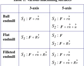
The following table gathers surfaces to be re-garded as machining surface according to the type of tool and the number of axes used for machining. R r Ssup S1 Sinf S2 Sn CL CC u n K f Φ ξ( 1,ξ2) Φsup(ξ1,ξ2) = Φ ξ( 1,ξ2)+(r+R)⋅N(ξ1,ξ2) u f Φin f(ξ1,ξ2) = Φ ξ( 1,ξ2)+r n⋅ (ξ1,ξ2) u n u F(ξ1,ξ2) Φgu i(ξ1,ξ2) Φgu i(ξ1,ξ2) F(ξ1,ξ2)+rn(ξ1,ξ2) = u(ξ1,ξ2) Φori(ξ1,ξ2) Φo ri(ξ1,ξ2) F(ξ1,ξ2)+rn(ξ1,ξ2)+u(ξ1,ξ2) = Φo ri(ξ1,ξ2) F(ξ1,ξ2)+Rv(ξ1,ξ2) = Φo ri(ξ1,ξ2) F(ξ1,ξ2)+rn(ξ1,ξ2)+Rv(ξ1,ξ2) = v u∧n u∧n ---∧u =
We propose to build the guiding and orienta-tion surfaces according to the method descri-bed in [7] because S1 and S2 are generalised offset surfaces. S1 and S2 are modeled by a multi-patch surface. Patches are bi-cubic in-terpolants connected in tangency. Each patch is expressed as a Ferguson tensor product surface :
with C the matrix of blending function (cubic Hermite basis) and Q the Coons matrix [8]:
where Φ(ξ1,ξ2) is the implicit equation of the guiding or orientation surface. In order to keep the consistency of the surface representation in the CAD system, we use a Bezier (UNISURF) representation for patches :
with M the cubic Bernstein basis matrix and B the matrix of the Characteristic Polyhedron vertices expressed as :
The precision obtained on surfaces S1 and S2 is proportional to the number of patches. From a point K on S1 one finds the corresponding point CL on S2 with the assumption that para-meter setting of S1 and S2 are identical. Thus the method generates approximations. The errors on the guiding surface S1 must be controlled because they cause local gouging between the tool and the nominal surface at the CC point. We have to use a large number of patches in the offset surface approximation to perform a precise machining. On the other hand, errors on the orientation surface S2 pre-sent fewer disadvantages because the varia-tions of orientation of the tool axis do not generate machining errors. Indeed, the con-trolled point is the point K which is the instan-taneous center of rotation during two rotations of the tool. The orientation of does not in-fluence the position of the active part of the to-ol. Moreover the tool radius R reduces the amplitude of the variations of S2 on the orien-tation of the axis tool (Fig. 8). The maximum angle variation is given by :
Figure 8 : Variation of tool axis orientation
In conventional generation of tool path with a filleted endmill, the rotation Ωt is done around (CC, ) [6]. The CC point is then the instanta-neous center of rotation. Since CC is the
con-tact point between the tool and the surface, the tool is rolling on the surface at CC. If there is an error in the calculation of the orientation of the tool axis, a collision appears at the CC point.
Example : The treated example consists in machining a surface (a Bezier patch of degree 5) with a filleted endmill (R = 10, r = 4) and
Table 1: Various machining surfaces 3-axis 5-axis Ball endmill S1: S1: S2: Flat endmill S1: S1: S2: Filleted endmill S1: S1: S2: F+rn F+rn F+rn+u F+Rv F F+Rv F+rn+Rv F+rn F+rn+Rv r u v( , ) = UCQCTVT Q00Q01Q02Q03 Q10Q11Q12Q13 Q20Q21Q22Q23 Q30Q31Q32Q33 Φ(0 0, ) Φ(0 1, ) Φ ξ2(0 0, ) Φξ2(0 1, ) Φ(1 0, ) Φ(1 1, ) Φ ξ2(1 0, ) Φξ2(1 1, ) Φ ξ1(0 0, ) Φξ1(0 1, ) Φξ1ξ2(0 0, ) Φξ1ξ2(0 1, ) Φ ξ1(1 0, ) Φξ1(1 1, ) Φξ1ξ2(1 0, ) Φξ1ξ2(1 1, ) = r u v( , ) = UMBMTVT B = (M–1C)Q M( –1C)T u αmax tan ε R ---= CC CL u n K f ε R S S1 S2 α CL* u∗ α t
with the following strategy: 5-axes milling, tool center guiding along parallel planes to yoz and Ωt= 20°, Ωn= 0°. S1 is the offset sur-face of Sn with an offset distance equal to 4 mm. S2 is the generalised offset surface
( ) with offset distance equal
to R = 10 and r = 4. S1 and S2 are free from loops. The modeling of the kinematics of the displacement of the tool on both surfaces S1 and S2 made it possible to simulate the machi-ning along the curve C1 (Fig. 9), intersection of S1 with the guiding plane. C is the contact curve followed by the CC point on the nominal surface and C2 is the curve followed by CL on the orientation surface.
Figure 9 : Machining simulation
Concluding remarks : The concept of the machining surface offers a new solution to ge-nerate toolpaths. Its construction is common to the various cutting tools usually used. The guiding surface creation is only based on the corner radius of the considered tool, indepen-dently of the machining strategy. The plan-ning of the tool paths is carried out initially by choosing curves on the guiding surface. Then if necessary, the surface of orientation makes it possible to position the tool for machining with five axes.
The objective is now to use the machining sur-face to generate successive tool paths on a compound surface. To achieve this task, we will have to introduce technical surfaces in the machining surface framework to be able to add approach, retract and linking macros. We are also working on another method to build the orientation and guiding surface. The method would be based on the two fundamen-tal forms to evaluate the local characteristics of the orientation and guiding surfaces.
Indeed, the current approach is difficult to im-plement. The encountered difficulties come from several factors : the loops resulting from the offset operation, the need for synchroni-zing the parameter settings, the number of pat-ches required to achieve hight quality machining.
References :
[1] E. Duc, C. Lartigue, C. Tournier, P. Bourdet,
A new concept for the design and the manu-facturing of free-form surfaces: the machining surface. Annals of the CIRP - 1999, vol 48/1,
103-106.
[2] E. Duc, Usinages des formes gauches,
contribution à l’amélioration de la qualité des trajectoires d’usinage. Thèse de Doctorat
ENS Cachan, 1998.
[3] C. Lartigue, E. Duc, C. Tournier,
Machi-ning of free-form surfaces and geometrical specifications, IMechE 1999, Proceedings of
the Institution of Mechanical Engineers Vol. 213 Part B, 21-27
[4] B.K. Choi, C.S. Lee, J.S Hwang, C.S. Jun,
Compound surface modelling and machining,
Computer Aided Design, 1988, vol 20, no 30, 127-136.
[5] B.K. Choi, J.W. Park, C.S. Jun, Cutter
lo-cation data optimization in 5-axis surface ma-chining, Computer aided Design, 1993,
vol 25, no 6, 377-386.
[6] Y.S Lee, Admissible tool orientation
con-trol of gouging avoidance for 5-axis complex surface machining, Computer Aided Design,
1997, vol 29, no 7, 507-521.
[7] R.T. Farouki, The approximation of non
degenerate offset surfaces, Computer Aided
Geometric Design, 1986, no 3, 15-43.
[8] I.D. Faux, M.J. Pratt, Computional
Geo-metry for Design and Manufacture, 1979,
El-lis Horwood Ltd, Chistester.
S2 =Sn+rn+Rv
C1 C C2
Appendix :
Figure 10 : Torus geometry
Implicit equation of the torus :
Normal vector to the torus at M0:
Let D1 and D2 be the two lines passing throu-gh the normal vector and the tool axis vector :
The distance between the two lines is d :
If M1 is the origin of the coordinate system, we find :
whatever the location of the point M0 on the torus. The two lines D1 and D2 intersect.
D1 z D2 n M0 M1 S x y z( , , ) = (x2+y2+z2+d2–r2)2–4d2(x2+y2) nx ny nz S’x 4x0 x0 2 y02 z02 d2–r2 + + + ( )–8d2x = S'y = 4y0(x02+y02+z02+d2–r2)–8d2y S'z = 4z0(x02+y02+z20+d2–r2) = D1 OM = OM0+µ⋅n D2 OM = OM1+λ⋅z d (OM0–OM1)⋅(n∧z) n∧z ( ) ---= OM0⋅(n∧z) = (x0i+y0j+z0k)⋅(ny⋅i–nx⋅j)