Design for Low-Power High-Density Helmet
Dispensing and Collection Systems for Urban
Environments
by
Arni Aleksi Lehto
and
Charles Christopher Mills
ARCHIVES
MASSACHUSETTS INSTITUTE OF TECHNOLOLGY
JUN 2 8 2011
LIBRARIES
Submitted to the Department of Mechanical Engineering
in partial fulfillment of the requirements for the degrees of
Bachelor of Science in Mechanical Engineering
at the
MASSACHUSETTS INSTITUTE OF TECHNOLOGY
June 2012
[ilke.201
C
2012
Arni A. Lehto and Charles C. Mills. All rights reserved.
The authors hereby grant to MIT permission to reproduce and
distribute publicly paper and electronic copies of this thesis document
in whole or in part.
Authors ...Certified by.
Accepted by.
Signature redacted
Signature redacted
Department of Mechanical Engineering
/
."
.,
'
/
/May
11,,2012
...
Signature redacted
David Robert
Wllace
Professor of Mechanical Engineering
Sg
atu
rVicar
Faculty Fellow
Sig nature redacted
esisSupervisor
John H. Lienhard V
Samuel C. Collins Professor of Mechanical Engineering
Undergraduate Officer
MITLibraries
77 Massachusetts Avenue
Cambridge, MA 02139 http://Iibraries.mit.edu/ask
DISCLAIMER NOTICE
Due to the condition of the original material, there are unavoidable flaws in this reproduction. We have made every effort possible to
provide you with the best copy available. Thank you.
Despite pagination irregularities, this is the most complete copy available.
Thesis page count runs from 1-73. Appendix A follows with
pages numbered 1-40. Appendix B to the end continues from
page 115-142.
Design for Low-Power High-Density Helmet Dispensing and
Collection Systems for Urban Environments
by
Arni Aleksi Lehto
and
Charles Christopher Mills
Submitted to the Department of Mechanical Engineering on May 11, 2012, in partial fulfillment of the
requirements for the degrees of
Bachelor of Science in Mechanical Engineering
Abstract
In this thesis, we designed and implemented a machine to dispense and collect helmets for bikeshare programs such as Boston's Hubway. Design of the machine was guided under several constraints including size and power for tight integration with existing bikeshare stations. The machine itself is divided into subsystems, including dispens-ing, reloaddispens-ing, and return components as well as software and electronics, power, and industrial design choices. The first prototype of the machine was implemented in December 2011, with refinement of the mechanisms occurring between January and May 2012.
Thesis Supervisor: David Robert Wallace Title: Professor of Mechanical Engineering
Acknowledgments
We'd like to thank David Wallace, David Meeker, Nicole Friedman, and Robert Fenner for all of their advice, support, and mentorship throughout our research. We couldn't have done it without you.
Contents
1 Introduction
1.1 Bikesharing . . . .
1.1.1 Growth . . . .
1.1.2 Importance . . . .
1.1.3 Challenges for helmet use in
1.2 Thesis Overview . . . .
1.3 Machine Overview . . . .
1.3.1 Key Design Considerations .
2 Dispensing 2.1 Design Requirements . . . . 2.2 Earlier Versions . . . . 2.2.1 Carousel . . . . 2.2.2 "Pez" Dispenser . . . . 2.2.3 The Tube . . . . 2.2.4 The Claw . . . . 2.2.5 Keyhole Plates . . . . 2.3 Current version . . . . 2.3.1 Mechanism Overview . . . .
2.3.2 High-cycle failure modes . .
2.3.3 Possible Refinements . . . . bikeshares 15 15 15 16 16 17 18 18 21 21 . . . . 2 2 . . . . 2 2 . . . . 2 3 . . . . 2 4 . . . . 2 5 . . . . 2 7 . . . . 2 9 . . . . 2 9 . . . . 3 2 . . . . 3 2
3 Reloading 35 3.1 Design Requirements ... . 35 3.2 Current version . . . . 36 3.2.1 Mechanism Overview . . . . 36 3.2.2 Failure modes . . . . 36 3.2.3 Possible Refinements . . . . 37 4 Return 39 4.1 Design Requirements . . . . 39 4.2 Earlier Versions . . . . 40
4.2.1 Two-door with trapdoor . . . . 40
4.2.2 L-door (trashcan) . . . . 41
4.2.3 Sliding Drawer . . . . 41
4.3 Current version . . . . 43
4.3.1 Mechanism Overview . . . . 43
4.3.2 Possible Refinements . . . . 44
5 Software and Electronics 47 5.1 Design Requirements . . . . 47
5.2 Web Application . . . . 48
5.2.1 Current Web Application Structure . . . . 49
5.3 Database . . . . 51 5.3.1 Database Structure . . . . 52 5.4 Systems Control . . . . 54 5.4.1 Current System . . . . 54 5.4.2 Possible Refinements . . . . 55 5.5 Wireless communication . . . . 56 5.5.1 Hardware . . . . 56 5.5.2 Transaction . . . . 57 5.6 Payment Processing . . . . 57
6 Power 59
6.1 Power Requirements ... ... 59
6.2 Solar Panel Use . . . . 59
7 Industrial Design 63 7.1 M achine Shape . . . . 63 7.1.1 Space Constraints . . . . 63 7.1.2 Paneling . . . . 64 7.1.3 Vandalism . . . . 65 7.2 Interfaces . . . . 67 8 Conclusion 71
A HelmetHub Business Plan 73
B ZU-1890M Credit Card Reader 115
C RFID Readers, ID-12 and ID-20 119
D Arduino processor 121
E Wireless Router 125
F Large LCD (Dispense) 129
G Small LCD (Return) 133
H Resistive Touchscreen 135
List of Figures
1-1 Transportation Modes in Urban Environments as a function of Trip
D istance[17] . . . . 16
2-1 First Prototype of Carousel-type Helmet Dispensing Mechanism . . . 22
2-2 The "Pez" Dispensing Mechanism . . . . 23
2-3 The 4-stage Dispensing Process . . . . 24
2-4 4-stage throat dispensing mechanism model . . . . 25
2-5 2-stage Dispensing Mechanism Prototype with Grasping Mechanism . 26 2-6 Claw-type grasping mechanism . . . . 26
2-7 Parralel Plate Unibody Dispensing Mechanism . . . . 27
2-8 Proof of concept for parallel plate-type dispensing mechanism . . . . 28
2-9 Dispensing Plate Design Parameters . . . . 28
2-10 Rod Driven Dispensing Mechanism, Drawing . . . . 30
2-11 The Two Stops and RFID Reader . . . . 31
4-1 The First Version of a Sliding Mechanism, Drawing . . . . 42
4-2 The First Version of a Sliding Return Mechanism, Isometric View . . 43
4-3 Sliding Return Box, Drawing . . . . 44
4-4 Sliding Return Box, Closed . . . . 45
4-5 Sliding Return Box, Open . . . . 45
5-1 The front page of the web application . . . . 49
5-2 Inventory page for a machine . . . . 49
5-4 Helmet transaction history page . . . . 51
5-5 Relational database model . . . . 52
7-1 The Dispensing (Left) and Return (Right) Machines as Separate Entities 64 7-2 Current machine design mocked-up beside bikeshare station . . . . . 64
7-3 The Tamper-Resistant Security Torx Screw . . . . 65
7-4 The helmet catch mechanism in the dispensing area . . . . 66
7-5 The Dispensing Control Panel . . . . 67
List of Tables
6.1 Power Requirements for Machine . . . . 60
Chapter 1
Introduction
1.1
Bikesharing
Bikesharing programs are short term urban bicycle rental schemes that enable bicycles to be picked up at a self-service station and returned to any other station. People use bicycles on an "as-needed" basis and the system eliminates the cost and responsibility of ownership while promoting cycle use within urban environments, helping people realize the advantages cycling offers against automobiles and public transit systems.
1.1.1
Growth
Although it has been present in one form or another, recent advances in mobile networking technology have enabled growth of bikeshare programs around the world
by making the transaction process simpler for users, and the tracking of bikes easier
for the bikeshare operator. As of 2010, there are approximately 160 bikesharing programs around the world, with a 74% increase year over year [16]. Program growth has continued to accelerate in North America, with 15 US cities already hosting their own bikeshare programs and more planning to launch programs in the coming year.
Within existing programs, the number of stations is expected to increase annually as well, with NY adding 600 stations in 2012[11], and Boston adding 30 stations as well[14]. This growth is due to popularity and success of bikeshare programs among
users in these cities, who view the programs in a largely positive light.
1.1.2
Importance
Bikesharing programs serve an increasingly important role for urban transportation
by providing the "last mile form of mobility in the public transportation hierarchy, as
can be seen in Figure 1-1. These programs also help to decrease emissions, increase public health, and improve the public image of a city while using little infrastructure and requiring a low investment compared to other forms of public transportation[17,
p.18].
Figure 1-1: Transportation Modes in Urban Environments as a function of Trip Distance[17] I nterety inrerdty Train o Suburbs Wh tps p t e Crtirase sPreart Public Transportation % D~dna~mTRAVEL DISTANCE
With city population densities projected to continue to increase, its clear that bikeshare programs have the potential to increasingly shape urban transportation in many positive ways.[12]
1.1.3
Challenges for helmet use in bikeshares
According to a report from the United Nations on bikeshare programs, the issue of helmet use was identified as one of 5 challenges faced by bikesharing programs[13,
"The self-serve nature of bicycle -sharing programmes limits their ability to provide helmets.. .for many people this poses a safety risk" [13].
The results of this report indicate that the challenge of providing an adequate supply of helmets is a worthwhile undertaking in the context of promoting bikeshare programs.
TTo quantify this impact, a recent study conducted by Beth-Israel indicates that approximately 80% of bikeshare users in Washington D.C. and Boston, MA do not use a helmet while cycling, less than half the rate of helmet use compared to cyclists who used their own bikes. [10] Additionally, men were at a higher risk of riding unhelmeted when compared with women, as were weekend riders compared to weekday riders.
The study concludes that the "Use of bicycle helmets by users of public bikeshare programs is low. As these programs become more popular and prevalent, efforts to increase helmet use among users should increase." [10] This conclusion corroborates the primary motivation of designing a machine to increase the number of helmets dispensed in bikeshare programs, and lends credibility to the belief that a machine such as ours that makes helmets readily available and convenient at the same location as the bikeshare station should increase helmet use among users.
1.2
Thesis Overview
This thesis articulates the design requirements and process for a bike helmet dis-pensing machine, and describes a prototype machine built to these specifications. Chapter 1 is an introduction to the bike sharing market and an overview of the pro-totype. Chapter 2 focuses on the dispensing mechanism development and Chapter
3 and 4 detail the helmet reloading and return mechanisms. Chapter 5 includes the
design of the electronics hardware and software operated in the machine. Chapter 6 outlines the power requirement and feasibility calculations for the prototype. Chapter
7 is an exploration of the industrial design concepts and requirements. Chapter 8 is
1.3
Machine Overview
1.3.1
Key Design Considerations
Consumer Behavior
In order to design a machine capable of dispensing and collecting helmets in bikeshare systems, the way in which users interact with the kiosks is important. The bikeshare kiosks are largely autonomous, mobile and self-serving meaning that a machine de-signed to incorporate helmets into the market needs to be similarly autonomous, mobile and self-serving. Many users of the bikeshare programs rent a bike sponta-neously instead of purchasing a monthly membership. The spontaneous nature of the users means that they are unlikely to have a helmet at the time they decide to rent a bicycle, and that helmet acquisition should be conveniently located with respect to the bikeshare kiosks.Hubway[5] currently displays a map along the stations that shows the nearest place to acquire a helmet, but these areas are far from the stations, and too sparse in the city, and as a result are ineffective in supplying helmets to bike-share users. According to usage data from Hubway, a method for supplying helmets to bikeshare users would need to be able to supply at least 12 helmets a day/week in order to match current usage rates. Similarly, helmets that are dispensed should be able to be sized appropriately for users, and should be ready to use without removing packaging in order to minimize waste and maximize convenience for users.
Size
One of primary advantages of bikeshare programs in urban spaces is the vehicle density they can achieve. In order to successfully integrate into these spaces with minimum impact to existing station designs, our machine needs to be at most 24" wide by 48" long. Fitting these dimensions allows our machine to occupy the space currently used for maps and advertisements, while still preserving the ability to display both maps
Power
In order to be rapidly and maximally deployable and environmentally friendly, bike-share programs are solar powered and wireless, two constraints that would need to be matched in designing our machine. The use of solar power in urban environments, where solar panels can suffer lower performance from dust and dirt accumulation, de-creased sun exposure in the shadows of buildings, and the usage of the machine long into the night means that the power budget for the machine needs to be minimal.
User Experience
A key concept throughout the development of this machine for us was that of a
fun, unique user experience. We dont believe that vending machines have to be mechanical distributors that unemotionally spit out the consumers product of choice. Instead we want to attempt to transfer the customer-salesman interaction from stores
into the world of vending machines. To represent this goal, we attempt to make each mechanism in the machine user actuated, or at the least require more of an interaction than simply pushing a button, in an attempt to make the machine more memorable. User actuation in turn will help us meet our energy budget of being a stand-alone machine, as it decreases the amount of electrical components necessary.
Chapter 2
Dispensing
2.1
Design Requirements
A good starting point to summarize the design requirements for our dispensing system
is to consider the main aspects of operation that will allow us to maximize efficiency of the machine. One of the two main factors is maximizing helmet storage capacity in the dispensing side, while minimizing the size and power requirement of the machine.
The larger the capacity of the machine is, the longer it will allow the machine to go without maintenance, and as a result will decrease our operating costs. Initially Hubway requested a capacity of 12 helmets per machine based on their statistic that there was an average of 12 rides per station per day in the Summer of 2011. However, the frequency of use of a station has great variance among the city with the most used stations averaging 70 trips per day downtown. As such, considering our desire to maintain a footprint that does not exceed that of a traditional vending machine, and limiting our height to around 7ft, we determined that our capacity goal would be to fit 36 helmets in one machine.
2.2
Earlier Versions
2.2.1 Carousel
The dispensing mechanism underwent several rapid iterations in design in order to best fulfill the design requirements. The first prototype was essentially a large par-titioned carousel, which rotated the helmets through an area that could be accessed
by an automated outer door sliding open and closed, as shown in Figure 2-1.
Figure 2-1: First Prototype of Carousel-type Helmet Dispensing Mechanism
Once a helmet was removed, the door was locked and the carousel advanced the next helmet into the area. The design had several such carousels stacked on top of each other. This iteration posed several challenges to the design requirements. The power requirements for the motorized carousel were considered to be too high to be feasible, and the utilization of space and the packing density of helmets were both too far from our design requirements.
a group of Engineers dedicated to creating an innovative solution to the problem of helmet vending, mimicking a failed machine was not the correct approach.
2.2.2
"Pez" Dispenser
The next iteration of the mechanism developed the concept of stacking the helmets vertically in order to improve the space and density specifications. By stacking the helmets on top of each other, they were slightly nested within one another. This decreased the volume consumption of a helmet by around 20% compared to stacking the side by side. This was also the first iteration that moved to a manually operated dispensing mechanism in order to meet the power requirements, and our goal for a more interactive experience.
Figure 2-2: The "Pez" Dispensing Mechanism
This design held helmets in a vertical stack on top of a spring-loaded base, as shown in Figure 2-2. As users opened the lid of the machine, helmets would be individually separated from the stack and advanced toward the users to take. This prototype was abandoned in its design phase as it became clear that the mechanical complexity of the dispensing mechanism caused significant challenges in implementation and questions of reliability.
2.2.3
The Tube
In the next iteration, the concept of dispensing helmets from the bottom of the stack instead of the top was developed. By dispensing from the bottom of the stack, the design could be significantly simplified by removing the complicated lifting mechanism from the base and allowing gravity to do most of the work. The dispensing process was split into four stages, as shown in Figure 2-3
Figure 2-3: The 4-stage Dispensing Process
Constrain Helmet Stack Open Dispensing Mechanism Close Dispensing Mechanism Release Helmet Stack
This process was implemented into a design shown in Figure 2-4, where the helmets are held in place using a flexible throat, actuated by a solenoid. Beneath the throat assembly, there is a trap door that is locked/unlocked by a solenoid. The distance of the trapdoor beneath the throat is designed so that while the rest of the helmet
stack is held in place by the throat, the bottom-most helmet is not, and when the trapdoor is unlocked, it swings open, and the helmet falls off the bottom of the stack and into the dispensing area. When the trap door closes, the throat opens and the stack drops down onto the trap door. Once the throat closes, the remainder of the
stack is held in place and the mechanism is returned to its initial state. Figure 2-4: 4-stage throat dispensing mechanism model
F~rA.. ... ... . .... .
This design was carried through to the prototyping stage, but quickly it became clear it was infeasible because of a lack of components that could address the power and material properties needed for it to function. The solenoid needed to actuate the throat mechanism needed a throw length and force beyond the specifications of readily available for our power requirements, and a linear actuator proved to be too costly for both our fiscal and power budgets, as well as being too slow. In addition, there were questions on the ability of the flexible throat being able to constrain a tall
stack of helmets through the friction generated by its spring-like properties alone.
2.2.4
The Claw
The design was once again iterated by re-examining the 4-stage process outlined in Figure 2-3 and simplifying it to two stages by combining the "constraining helmet stack" and "opening dispensing mechanism" states, as well as the closing dispensing mechanism and releasing helmet stack states. This simplified process led us to ex-plore designs in which constraining the helmet stack was coupled with opening the dispensing mechanism under the assumption that it would simplify our design.
Figure 2-5: 2-stage Dispensing Mechanism Prototype with Grasping Mechanism
Fo.NdrswkU.do 01*.
crrT
... ... .- -.. ... ... -. .... .... ..- -- --- -
--Figure 2-6: Claw-type grasping mechanism
The first implementation of this new process was a mechanism affectionately dubbed "The Claw", as shown in Figure 2-5. "The Claw" operated by using a linear motion of pulling a handle to simultaneously withdraw a platform from beneath the helmet stack and pull on a linkage attached to a 4-bar claw mechanism shown in Figure 2-6. When the platform was fully removed from under the stack, the compres-sive force from the claw would hold the helmet stack up. The platform was allowed to travel beyond the point where the claw held the helmet stack by attaching the actuating linkage to a spring. This way, the farther the handle was pulled, the tighter the claw would grasp the helmet stack.
With the claw, we realized that the helmets could be held in a rigid stack by using a rod that ran through the central ventilation holes of the helmet. This allowed us to decrease the constraints around the helmets in the form of large guide plates, while
maintaining the nesting property of the helmets to maximize the packing efficiency. This design was carried through to implementation, but failed because of considerable complications. The number of moving parts required careful coordination in
assem-bly to ensure the mechanism would perform reliaassem-bly, and the entire mechanism was
large in geometry, especially vertically. Linking the entire mechanism increased the complexity, and in addition the force required from the user to actuate the system was too high, and is this became apparent, the claw mechanism was abandoned to
try and find a simpler solution.
2.2.5
Keyhole Plates
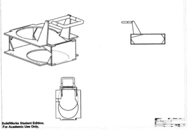
Figure 2-7: Parralel Plate Unibody Dispensing Mechanism
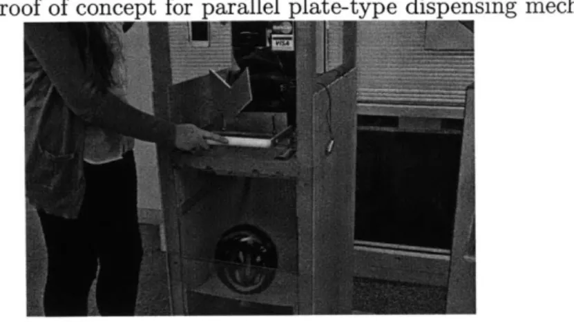
In examining the way the claw mechanism worked, it became clear that the two most important principles in its operation were that the bottom helmet was only free to fall after a point where the upper helmets constrained, and that the upper helmets should only be free once they were constrained by the dispensing plate was in place to hold them. This led to the final design iteration utilizing two parallel plates with offset keyholes for both the constraining plate and the dispensing plate in one unified mechanism. The concept was proven in Figure 2-8 and refined into the mechanism
used in the alpha prototype shown in Figure 2-7.
The mechanism dimensions were designed so that the keyholes were large enough for clearance with a falling helmet, modeled as an ellipse. Their centers were offset
Figure 2-8: Proof of concept for parallel plate-type dispensing mechanism
by the throw length of a handle attached to the mechanism so that the helmet would
only fall through the plates at either the fully open or fully closed positions.
The design parameters of the plates are illustrated in Figure 2-9 as a function of helmet dimensions and the throw length of the actuating handle.
Figure 2-9: Dispensing Plate Design Parameters
Constraining Ellipse
Center-to-center distance
JI is equal to the throw
length of the dispensing handle
Clearance
Ellipse-Keyhole is a spline fit between the two ellipses
This design was implemented in the alpha prototype as a proof-of-concept for low power helmet dispensing from the bottom of a vertical stack.
Both the claw and the alpha prototype reflected the user actuation design require-ment well. However, after user surveys we have realized that there is a necessity for stocking various sizes of helmets. The control of which helmet size is dispensed (as-suming they are separated by size in stacks) is difficult by solely mechanical means, and would require a somewhat more advanced, electronically controlled gearbox or switch to link to the user control mechanism.
As a result, the current dispensing mechanism design is electronically actuated, however this approach is taken mainly to provide for a working prototype in a faster timeframe. Future design will attempt to incorporate user actuation on the dispensing side again.
In addition the physical size of the keyhole mechanism makes fitting multiple stacks of helmets into our constrained space very difficult, and moved us to design a new solution, which had the main design criteria of occupying as little footprint as possible. To approach this in a novel fashion, we decided to utilize an already existing part of the machine, the rod holding the helmets in a stack. If the dispensing could be performed using solely the rod, this would allow us to decrease the footprint of the dispensing mechanism significantly.
2.3
Current version
2.3.1
Mechanism Overview
The current iteration of the mechanism is the first machine developed to utilize the ventilation holes of the helmets to their full potential. The current Bell helmets that we use have a central ventilation hole that is elliptical in shape, and we modeled our dispensing system to take advantage of their unique geometry.
Instead of only using the rod to hold the helmets in a neat stack, the rod will also be used to singulate the helmets from the machine. On the bottom of the rod we installed two physical stops that mimic the shape of the ventilation hole. The two stops are vertically offset from each other by 2.5" and also rotated 90 degrees in the
Figure 2-10: Rod Driven Dispensing Mechanism, Drawing
A
U SE1THW EC~FD N. DATE
7_Reloading AssemblySMNOE DWG. NO REV DA
ntdtFn A H H-RL
5H P~ 01M 3 f 2r
r I""T A I I A
horizontal plane with respect to each other. By rotating the shaft back and forth by 90 degrees, and maintaining the helmets in place rotationally, the mechanism is able to separate one helmet from the stack.
An REID reader is placed in between the two stops. By limiting the range of the
reader to a specified distance, it will read only the tag of the helmet that falls between the two stops in the transitional period. This will allow the machine to record which
helmet is being dispensed for each transaction.
The main benefit from this iteration is the decrease in space required around the
helmet for the dispensing mechanism, as was apparent with former versions. This will allow multiple stacks of helmets to be stored in the same ground footprint. Ideally we would be able to install three 12-helmet stacks in one machine for a vending capacity of 36 helmets.
In our mock-up model of the mechanism the physical stops will be round aluminum stock that is long enough to prevent the helmet from passing it sideways, but short
Figure 2-11: The Two StoDs and RFID Reader
enough to fit through the long dimension of the elliptical ventilation hole. By using a thin long protrusion instead of stop the fully follows the shape of the ventilation hole, it allows for some compliance in the radial direction to account for such factors as misalignment of the pole, rotation of the helmet stack, and lack of accuracy of the drive mechanism.
The shaft will be rotated with the use of a 180 degree rotation servomotor, which is an ideal controller due to its accurate position feedback system. The mechanism will be geared so that the range of motion of the servo will be sufficient to allow necessary rotation of the shaft, while maintaining enough torque.
2.3.2
High-cycle failure modes
The current design motion control has a fixed 90 degree angle of rotation of the shaft. Therefore the main mode of failure will occur if the stack of helmets changes angular orientation within the machine, or the stack is not uniform in direction. Either of these conditions could arise from either vandalism i.e. significant impact to the machine, or the stack rotating through contact with the moving dispensing mechanism. In addition to the physical stop being in contact with the bottom helmet, there are also contact points between the outside of the rod and the ventilation holes of the helmets. Interaction between these surfaces could cause the stack to shift slightly.
We have considered two different solutions to this problem: either use a second smaller, guide rod the threads through a side ventilation hole through the stack of helmets or introduce a funneling guide plate onto the bottom of the dispensing mechanism that would hold the 2-3 bottom helmets fixed in the angular direction.
Of the two possibilities the funneling guide plate seems to be more adaptable to
a variety of helmets, while the secondary guide rod might not be applicable for all types of helmets due to a lack of a second, appropriate ventilation hole. However, one concern for the guide plate is the constraint it introduces on the reloading system and possible interference with other helmet stacks. This is an issue that will require more extensive testing than we have had time to conduct to determine the amount of helmet motion that will occur as a result of the dispensing rod, and the negating effect of the above proposed solutions.
2.3.3
Possible Refinements
The current dispensing mechanism is limited to helmets that have an elliptical or oval center vent hole. However, a large number of different helmet styles (including all of Berns helmets, which is a large Boston based helmet manufacturer and an ideal future business partner) have a circular central hole. In order to facilitate our current design choice of embedding a dispensing mechanism in the central rod, the physical stops have to be dynamic with respect to the rod, instead of static, as they are currently.
Conceptual models to solve this issue have been brainstormed, of which one cur-rently rises as the most conceivable in terms of maintaining costs low and ease of manufacturing. It consists of two concentric rods, of which the outer rod would be fixed in both the longitudinal and angular directions. The inner rod would have two sets of spring-loaded clips attached on a hinge. When the inner rod is rotated, it allows for one of the sets of clips to extend through openings in the outer rod, and act as a stop for the helmet stack. An initial drawing of a possible solution can be seen below.
Ideally, the spring would be unnecessary and it would be possible to use a strip of metal that would bend elastically and perform the same function.
A future design problem to tackle is re-introducing user actuated control into the
system. To avoid the use of a complex gearbox or clutch system a possible approach to user actuating a number of stacks of helmets could be to offer multiple handles on the user interface of the machine, which are unique to each stack. This way the user could choose the size helmet they wish by actuating the corresponding handle.
Chapter 3
Reloading
3.1
Design Requirements
The main requirements for the reloading mechanism of the machines can be expressed
by two different factors: it needs a simple mechanical interface, and it has to be as fast
as possible to use. As the dispensing mechanism is dependent on holding the helmets on a vertical rod, we grouped all possible reloading solutions into three different groups defined by the basic geometry of how it would be reloaded: bottom feeding helmets on to the pole while it is still attached to the machine, removing the pole and top feeding the helmets on to the pole, or replacing the empty pole with an already stocked pole. Our current dispensing mechanism is actuated from the top of the pole through a gear system. Removing the pole completely would require an easy-locking mechanism to be designed into the drive system, and for the pole to be correctly oriented each time before reattachment. If the pole is not oriented, there is a distinct possibility of the dispensing mechanism failing during use.
The next generation design of the dispensing mechanism, which will be functional for circular ventilation holes as well, will not have a constraint on its angular position. Depending on the eventual actuation mechanism, the issue of disengaging the rod may not be an issue.
In addition, the rod replacement strategy requires a large stock of dispensing rods to allow for multiple machines to be reloaded in day and not be limited by the
amount of rods. The additional rods would constitute an extra capital cost for the process to be possible. Further economic analysis into the reloading time and cost of maintenance against rod cost would have to occur for a final decision to be made. Based on the analysis of our current requirements, and current design of the dispensing mechanism, we have chosen for our reloading mechanism to be bottom-feeding onto
a rod, which is fixed to the machine.
3.2
Current version
3.2.1
Mechanism Overview
The current reloading mechanism consists of the top plate, which the rod and dispens-ing drive system is attached, sliddispens-ing out of the machine completely on linear sliders. This allows for easy access to the rod for a maintenance workers, and no points of interference in the area near the bottom of the rod to slide helmets on to the rod.
The rod has two physical stops near the bottom, but the upper stop is hinged in one direction, which allows helmets to be slid up. As the helmet is slid up, the sides of the ventilation hole come into contact with the upper stop, which can hinge upward into the pole, making the width of the stop the same width as the rod. With this added feature, the maintenance worker reloading the machine does not have to rotate the helmet multiple times as he slides it on the pole, and must only align the central hole with the bottom stop. The bottom stop is kept stiff, however, for the reason to eliminate the possibility of user interference when the machine is in operation, by reaching up the dispensing opening and manipulating the lower stop.
3.2.2
Failure modes
One of the main modes of failure for the reloading mechanism is possible inaccuracy when the rod is slid back into position. If the rod is not returned to the appropriate position to align with the dispensing opening of the machine, it may result in failure to dispense any helmets. This problem can be avoided by using sliders that feature
an easy-stop and utilize that feature to determine the accurate positioning of the rod. This feature will make realigning the rod a very intuitive procedure for maintenance workers.
3.2.3
Possible Refinements
Depending on the dimensions and geometry of the layout of possibly multiple helmet stacks in the dispensing side of the machine in future iterations, the method by which the rod is moved outside the machine may have to be refined. Instead of using linear sliders, it may be more efficient to hinge the rod out of the machine around a pivot point. This could allow for a higher packing efficiency of helmets in the horizontal plane and keep the overall size of the machine down. This could also decrease costs by utilizing a bearing on a pivot point instead of linear sliders, which can be more complex, and expensive. In the case of pivoting rods, it is essential to have a feedback mechanism to determine the correct position of the rod with the machine, as mentioned in section 3.2.2 "Failure Modes".
Chapter 4
Return
4.1
Design Requirements
At a basic level return mechanisms in vending machines (e.g. RedBox[7]) have much more complex design requirements than most return receptacles, such as trash cans or recycling bins, we see in our environment. The main requirement as such is that the return mechanism should only be able to accept the product that it is designed for, and nothing else. For companies such as RedBox this is not that challenging of a demand as they have a product that is small, and has a geometrically unique shape. However, due to the size of a helmet the sheer size of the opening for return requirement raises an issue of different type of litter being thrown in, e.g. rocks, bricks and bags of trash, and possible vandalism. The design should be focused on creating as few opportunities as possible for vandals to introduce foreign content into the machine. Not only will this help maintain sanitary conditions inside the machine, but it will decrease costs of cleaning the helmets and create a healthier work environment for the staff who maintain the machines.
In addition, we also require that we are able to detect the presence of a HelmetHub helmet via the use of RFID both before unlocking the return mechanism in order to limit the accessibility of the return space to those who have a helmet on them, and inside the machine before the transaction is processed to confirm that a helmet has in fact been returned. As of this moment we see this as the most effective method to
prevent transaction fraud against us, and will decrease the amount of manual work on our back-end in the form of manually checking and registering which helmets have been returned.
Finally, as with the rest of the machine, we want the user experience to be both fun and interactive. The more unique the method the user interacts the machine, while maintaining a level of simplicity and ease of understanding for the user, the better the experience for the user will be, and the rate of retention of customers will be higher.
Based on this approach, we developed the following criteria for design
1. User actuated, interactive mechanism
2. The return door will not open unless an RFID tagged helmet is presented
3. When the mechanism is open
(a) it will only accept objects shaped like a helmet
(b) Other objects should either drop through the mechanism, or not fit into
it.
4. When the mechanism is retracted into the machine, it must detect the helmet again before completing the transaction
4.2
Earlier Versions
4.2.1
Two-door with trapdoor
The initial design for the return system was an independent return station, that was half the height of the dispensing machine. It introduced a modular approach that would allow us to allocate a unique ratio of dispensing-to-return capacity to each station.
The return mechanism involved a two-stage process, which consisted of an "air-lock" type system, where the helmet was first inserted inside the machine through a
front door, and once the front door was closed was dropped in to the return box via a trapdoor. This approach, however did not meet our 3rd design requirement of keeping trash out of the machine as it was possible to place trash into the machine through the front door. Even though the trash would not be dropped into the container, it remained inside of the machine and would be an obstruction and nuisance for the following customer, who would have to remove it in order to place their helmet in the machine. As such, this warranted a complete redesign of the return side of the machine.
4.2.2
L-door (trashcan)
The second iteration of the return mechanism involved a simple L-shaped door that is used in many of the solar-powered garbage compactors visible in public areas, including MITs campus. This design was a quick-solution for our alpha prototype machine to be presented at the end of 2.009[1] as a result of a quickly approaching deadline. While the design was simplistic, and elegant, it still did not meet our 3rd requirement to make placing trash in the machine a manually challenging and near impossible task as one could still place trash in the door and drop it in the machine. In addition it did not meet our 4th design requirement as the helmet would simply drop into the return box when the door was closed.
As a concept, our team still considers this the most cost-effective, user-friendly and ideal solution in an ideal world for returning a large object such as a helmet, however our concern for potential vandalism and helmets stewing in rubbish during the hot summer days makes this design solution an unacceptable one to implement
in the market-ready version of the machine.
4.2.3
Sliding Drawer
The third iteration of the return mechanism consisted of a cabinet-like drawer that slid out of the machine. The drawer slid on two concentric pairs of poles, and had a circular outer frame. The helmet was designed to be placed curved side down on to
the two poles, which were at such a distance that most garbage would fall through them. Once retracted back inside the machine, the handle could be rotated to force the helmet to fall into the machine. In the back of the mechanism, which was attached to middle wall of the machine, was a key mechanism that prevented the drawer from rotating when it was not fully retracted.
Figure 4-1: The First Version of a Sliding Mechanism, Drawing
UNLESS OTMEWSE SPECH31 NAVE DATE
TITLE:
tig
aonal Edljen D
FLC seC.A ENGy AM.N
5 432
There were a number of problems with this mechanism, that eventually led the team to do a complete redesign. The mechanism retracted too far outside the machine, ca. 12", which would not only be uncomfortable for the user, but would allow a significant amount of leverage for any possible vandals. The long throw also allowed for a considerable amount of space for trash to be thrown directly into the machine while the mechanism was only half-retracted. Finally, it became difficult to determine a position for the RFID reader to be placed appropriately that did not involve placing a horizontal beam between the two rods.
Figure 4-2: The First Version of a Slidi
4.3
Current version
4.3.1
Mechanism Overview
The most recent iteration plays off of the last return iteration by sliding out the return space from the machine. The return mechanism consists of a return box, with the top side open and shaped like a helmet, and the bottom side being nearly completely open, with actuated stops near the bottom that extrude into the opening only slightly. Geometrically the mechanism is designed to accept helmets with their longest dimension in the vertical axis, and the spherically curved top of the helmet facing the machine. By inserting helmets with this geometry, it minimizes the distance the mechanism extrudes from the outside face of the machine, and thus minimizes the leverage a possible vandal may have to attempt to break the mechanism.
There are two tabs on each sidewall designed to catch the helmet from the bottom.
By only protruding 1/2" on each side this creates the largest possible opening in the
middle of the machine to allow any non-wanted materials to simply drop straight through the return box and onto the ground. The tabs are actuated by twisting the front handle 90 degrees in either direction and are driven through a solid bar linkage.
By twisting the front handle the user also actuates two tabs on the bottom of the
Figure 4-3: Sliding Return Box, Drawing
SPCMD MME DATE
.O84S SIZ DWG .O REV... MCIN
F onaIEdtoLy. A returnbox2 O
machine that move vertically down. The purpose of these is to act as a mechanical stop for actuating the handle when the mechanism is outside of the machine, through interaction with the frame, and prevent premature helmet release inside the machine due to interaction with a locking mechanism. An RFID-20 REID reader will be placed in the fitted curved part at the appropriate height to detect the REID chip in the helmet independent of which direction the helmet is entered at. The box is attached to the middle plate of the machine by two linear sliders, which are each rated to 300
lbs at full extension.
4.3.2 Possible Refinements
The main refinement we see with the mechanism right now is the stopping tabs on the bottom have a small range of motion, ca. 1/2". This creates a requirement for any tolerance between the frame, the lock and the return box to be quite tight to allow minimal free "backlash" rotation of the handle when locked.
ure 4-5: Sliding Return Box, Open Figure 4-4: Sliding Return Box, Closed
In addition, the return box is quite large, which is due to the size of the helmet, and has a lot of area for possible vandalism or drawing.
Also, the shape of the box is cubical at the moment, and may not be the best looking solution. Once the mechanical aspect of this solution is proven, further de-velopment should go into making the mechanism appear sleeker and less bulky.
Chapter 5
Software and Electronics
5.1
Design Requirements
Once put into the field, the HelmetHub units would be required to record and send rental and return transactions and transfer credit card information from the reader to a centralized server. As one of the main physical design requirements of the machine was for it to be freestanding and free of any physical connection to the ground this communication will have to be done wirelessly, and considering the location of the machines and their mobility, this interaction would occur over mobile networks instead of wi-fi. We will be sending credit card information over these wireless networks, and therefore a major requirement is that we have a secure connection to our central server. The most straightforward option is to create a VPN network, however, more research into this subject has to done.
In addition to wireless communication, the software side of the infrastructure requires a database to track the movement of helmets and inventory of each machine. Also to ease the processing of the database information we have to build a web app that will compile necessary and relevant information on helmet movement patterns and the status of each helmet and machine. This web app needs to built on a platform that allows easy mobile interfacing, to keep maintenance workers who are moving around the city to be constantly updated on the stock of machines and respond quickly to shortages at specific stations.
To summarize the design requirements in a list, they are as follows:
1. Secure wireless communication over mobile networks
2. Database system for automated helmet tracking
3. Web app to ease user interaction with the database
5.2
Web Application
The design space for a back-end web application has a lot of room to implement advanced features, but would consist of the following basic necessities.
First
A list of machines with their location and their current stock of helmets in the
rental and return compartments. This would allow our maintenance workers to have an idea of which machines are next in turn for restocking and would allow consumers to check the locations of the closest machine to them and which
stations have a machine. Second
A full list of transaction history for each helmet. This will allow us to determine
the amount of cycles a helmet has been through, and how long it has been out on the market. This data is also very useful in tracking the most frequent routes and direction for helmet movement within the city.
The initial version of the web application was built using the Django[4] open source web application framework. Django is designed to allow for quick production of web applications in Python utilizing a relational database management system (MySQL in our case), by allowing developers to focus on coding the framework of operation and producing the relevant HTML code automatically from users specifications. The main benefits in our development situation were its small learning curve and turnover time to a functional application.
5.2.1
Current Web Application Structure
Figures 5-1 through 5-4 are collected screenshots of the bare necessities for a back-end application as presented earlier, with explanation of each pages functional purpose.
Figure 5-1: The front page of the web application
Machines
* 150 Massachusetts Ave Cambidge02139
* 2 32 Vassar Street Cambridge 02139
The front page of the application currently presents two dummy machines that I entered, which will be located at the two upcoming MIT Hubway stations in front of Stata and Bexley buildings. Currently it only shows a list of the machines, but ideally it would be developed to have an interactive map, perhaps integrated with Google Maps that would allow for a faster look-up of machines in a certain location.
By clicking on the hyperlink of the machine id number, it will take you to a page that
shows more detailed inventory information for that machine. Figure 5-2: Inventory page for a machine
Machine 1
50
Massachusetts
Ave
Cambridge,
02139
"
HelmetsforRent:0
" Helmets Retumed : 1
The machine inventory page shows the number of helmets in both the rent and return compartments of the machine. Once the capacity of a machine is increased to
36 helmets. It would be beneficial to separate the rent and return capacities to reflect
the availability of different sizes of helmets as well. In addition a nice expanded feature would be to see the average number of rentals per day, and the respective statistics
of the 2-3 closest machines to this one. This would allow insight into which machines are most used in the area, and could be useful in determining new installations or reallocation of machines.
Figure 5-3: Return stock of machine
Machine
1
Helmets Returned
#
Bel
3The following page is quite straightforward, and simply recounts the specific hel-mets in stock in the machine.
By clicking on a specific helmet you are taken to the helmet history page, which
shows all of the past transactions, both user and maintenance. As you can see this particular list is stocked full of transactions as a result of testing the underlying code. More information could be added to this page in the form of the time that the helmet has spent in rotation, and the amount of rental cycles it has been through.
In its current state the back-end software for monitoring machine use, inventory and helmet motion within the machines is inadequate, but represents a proof of concept for a very basic level of service that is required. In beta testing I see this structure sufficing due mainly to the small amount of machines and helmets in use, but with expansion significant effort should be made not only to make the system look nicer, but make it faster to navigate and be user-friendly for a maintenance staff that will not be as technologically proficient as the developer. Integration with already existing technology such as Google Maps would allow for the development of visual aids that could show rental frequency and helmet movement in ways that could assist in quick adjustments and consumer demand.
Figure 5-4: Helmet transaction history page
Bell
1 L
Sales No Type Date | MaCM IC"O
1 Rent Mr 6,2012, 11:8 a. |EI 9 ~IRent II March 6,2012,9:44 p.m. 1I] il]RMarch 6,2012,9:44 p.m. [ 13 11lel Cleannrg 6,2012,10:4 p.m. t
[-14
12 R nt March 6,2012,10:52 p.m. 1ZI
13]Rentlili] 6,2012,10:53 p.m. t[il116Z4I
March 6,2012, 10:54 p.m. b 2Wl7IMove
to I 6,2012,11:06 p.m. |1 | 16ICI] ningI 6,2012,11:15 p.m.17 Fiii edCkming I March 6,2012,11:20 p.m. b
[
18I] est k MFAi 6,2012,11:20 pa.m. b ill19ll]ck piii 6,2012,11:43 p.m. 1|
i]*l
eL] kMarch 6,2012,11:43 .m. |il2l6] ,2012, 11:43 p.m. t 1 53Reock Mah 6,2012, 11:44 pDatb*ae11 I 2a sReS ak bnmad 6,2012,11:45 posble T
o t tagesmck oacke6,2012,11:5 . arcue n1d t am o ex esock inw h 7,2012,12:05 atm.
27 Reslck Marc 7,2012, 12:12 tam d I| I8 Mard7, 2012, 1:07 axm. JtW 1 -1 29 RetckM1c 7, 2012, 1:47 am rmb 1
30 Resb wk_ MFArc 7,2012, 1:47 a JQ. _11 |
5.3
Database
The database structure has been made to be as simple as possible. This is a result of both the initial stages of set-up for a back-end infrastructure and the lack of large
amounts of experience working with database systems.
The relational database management system of choice for this project was MySQL[6].
MySQL is the most commonly used software for this purpose and is both easily
inte-grated with the hardware used in development and the Django software used in the web application.
5.3.1
Database Structure
Figure 5-5: Relational database model
Id VINI)A ---oali INT(01) ot* VARCHAFI(10) Manuhature VARCMAR25) $ine VARCHAR(G) fWWral~ro VAf%*AMM) WwebXWetn VARcHAW5) Ild VARCHAR(20) Id WT(11) address VARCHMAR100) zipoode VARCHAR(0) dly VARCKAR(S0) SmM VARCHAR(50) id I11)b sawiM "1T1)
L t& UNKMU seedS"-W$"jM~k9
I INT(11) 00 so.M.d.s ATEME UntWL VARCHAR(S) amkBmerjdtINT(1 1) 0* ocIonMd Wr (1) 0 transmdonyp VARCHAR(30) Overview
The database consists of five tables, which within them are able to contain enough information to track all movements of each helmet, all transactions that have occurred, and the inventory in each machine.
The annotations on the graph are as follows:
"A" Auto-increment, each new entry in the table gets a unique id number
"P" Primary Key, value in the table that uniquely identifies a table "F" Foreign Key, value that interconnects tables amongst each other "i" indexed value
]
"N" Not Null, an entry in this column of the table is required, a null entry is only
allowed in the sum total section for maintenance transactions and the helmet and sale location entries for maintenance purposes
Customer
The customer table as of now is very simplistic and only contains the customer number and the credit card that they used. In the initial beta testing stages we do not plan to have users register or buy a membership, and we simply consider each customer as unique. In the future this table would expand to include customer name and address and would allow us to track purchase history of each customer and habilitate registration of customers.
Sale
The sale table is the record of information for each sale, which can include several helmets, but only one customer. It records the date of sale, sum total of the sale and type of transaction. There are 5 different types of transactions that will be used
by our web application, two of which are user transactions and three of which are
maintenance transactions. The different transaction types are
" Rent
" Return
* Remove for Maintenance*
" Finished Maintenance* (i.e. has been cleaned and inspected)
" Restock*
As each helmet passes through each stage of the cycle, the transaction log allows us to determine what stage it is currently in by referring to its last form of transaction.
Transaction
The "transaction" table is simply an intermediate table between the "helmet" and
the "sales" table as they have a many-to-many relationship (one sale can have several helmets, and one helmet can be a part of several sales). Every helmet-sale relationship is linked uniquely through a transaction and each transaction is uniquely identified
by the combination of both the sale id and the helmet id.
Helmet
The "helmet" table contains all the necessary information of each helmet and its current state. The helmet is defined by its manufacturer, size and uniquely identified
by its RFID tag by the machine in a transaction. The rental and return price of
the helmet will be determined by the price at which we buy it, our price point in the market and the requirements of our customer and will be unique for each helmet type and market we are in. The status of the helmet is present in this table to allow quick look-up of which stage it is in of the cycle, and this value is updated during the transaction process.
Machine
The "machine" table is simply used to give every machine a unique id and location so that the machines positions are known and the physical movement of the helmets around the city can be tracked.
5.4
Systems Control
5.4.1
Current System
Microprocessor
The current model of the machine is controlled with an Arduino[2] microprocessor. The vending process is modeled as a state machine in the Arduino framework, which
is an intuitive solution for the developer to compare the different states of the machine to steps that the consumer takes in the transaction process. The software framework is designed to have both the dispensing and return side of the machine to be controlled with separate Arduinos.
User Interfaces
On the dispensing side of the machine the customer interacts with two different electronic interfaces: a credit card reader and a touch screen system. The credit card reader is used to gather the payment information of the customer, while the touch screen is used to navigate through the transaction purchase and determine the customers exact requirements for size and number of helmets they want.
On the return side, the customer will only interact with an RFID through the use of the helmet. They will receive information on the transaction process through a small LCD screen. The user does not swipe their credit card on the return side, as the refund will be credited to the credit card number that was used to purchase the
helmet initially.
5.4.2
Possible Refinements
The current control system creates extra costs and a more complex system to inte-grate. The plan in the short run is to modify the software structure to accommodate for both sides of the machine to be under one Arduino microcontroller. This will re-quire a more intricate design model for the software to avoid conflicts when accessing shared hardware resources. Since they do not share any electrical components for the operating mechanism or user interface, the only situation I see this a problem arising is the use of the connection to the wireless router.
In addition we will desire to move away from the Arduino product as we approach larger-scale manufacturing due to costs and limitations of the platform. One possible option is to either take the useful components and features from an Arduino and add other required components (e.g. Ethernet connectivity) into a custom PC board and
![Figure 1-1: Transportation Modes in Urban Environments as a function of Trip Distance[17] I nterety inrerdty Train o Suburbs Wh tps p t e Crtirase sPreart Public Transportation % D~dna~mTRAVEL DISTANCE](https://thumb-eu.123doks.com/thumbv2/123doknet/14682703.559610/17.917.175.694.494.804/transportation-environments-function-distance-inrerdty-crtirase-transportation-distance.webp)