An Active Seating System for Prevention of Pressure Sores
by
Gustavo Y. Buhacoff B.S. Mechanical Engineering New Mexico State University, 1995
Submitted to the Department of Mechanical Engineering in Partial Fulfillment of the Requirements for the Degree of
Master of Science in Mechanical Engineering at the
Massachusetts Institute of Technology June 1997
© 1997 Massachusetts Institute of Technology
All Rights Reserved
Signature of Author
Department of Mechanical Engineering May 23, 1997
Certified by:
Accepted by:
Woodie C. Flowers Pappalardo Professor of Mechanical Engineering Thesis Supervisor
Am A. Sonin Ain A. Sonin Chairman, Department Committee on Graduate Students
Eng.
MASSi ACi,!US-lT. TS iNS- TTU-T;" .-: OF TE:CHINOLO3Y UBRARIES MASSACHIUSETTrS INSTITUTE OF TECHNOLOGY
OCT 2 7
1999
LIBRARIES
mAn Active Seating System for Prevention of Pressure Sores
by
Gustavo Y. Buhacoff
Submitted to the Department of Mechanical Engineering on May 23, 1997, in Partial Fulfillment of the Requirements for the Degree of Master of Science in
Mechanical Engineering
ABSTRACT
A pressure management and relief system has been developed for use by wheelchair-bound individuals who are at risk of developing pressure sores. This system can be used in passive or active form, depending on an individual's requirement for pressure management and relief. The active seat uses vacuum and pressure in combination with an open-cell-foam-based cushion to perform pressure relief.
Testing methods for the system were studied and developed. These methods allow a controlled and precise testing of seating systems. Prototype systems have also been produced and tested. Experimental equipment and data are presented to support performance claims.
Prototypes of both active and passive systems have also been tested in a pilot clinical study to assess their effectiveness. Results from this study are presented.
Thesis Supervisor: Woodie C. Flowers
Acknowledgments
I would like to thank my parents, Ana & Richard Brewington and Carlos & Alicia Buhacoff, who always gave me the freedom and support required to make all the right decisions that
eventually led to this point.
Woodie Flowers, my advisor, who always seemed to believe this was going to be successful, even when we had doubts. I was once told that Woodie was so great to work with that if he offered an assistantship I should accept and only later inquire what it entailed. My
experience does nothing but support this advice.
Dean Kamen, who opened DEKA research and development to my fellow students and I, to contribute and learn, providing the funding to make it possible. His strong belief in the value of education in the sciences has allowed several other students to get invaluable experience working at DEKA. I sincerely hope he continues to offer this opportunity to many more students.
Michael Bush started working on this project as a graduate student and is now a full-time member of the DEKA team. Much of the credit for this work goes to him. He will also see this project to its completion. In the process, I am quite sure he will find that one idea he is looking for....
Charlie Grinnell, who was our supervisor at DEKA, always kept us on track and supported our work.
Jean Minkel, for sharing her knowledge and insight on this subject.
Bill Shea, for allowing us the generous use of his anatomy to make the plaster molds and for the insightful feedback on the prototypes.
Dave Mosher lent us his expertise in making the controller.
Everybody at DEKA, who in one way or another made a contribution to our effort, never forgetting to mention how "cushy" our job was.
Avi, Dafna and Zoe Cramer, who opened their house to me to make it my home away from home.
This page is not long enough to mention all the things for which I'd like to thank Tom Lee. However, it probably could be summed up in: thanks for being such a good friend.
To all my friends in Ashdown House, who helped make this such a good experience. And finally, to Lizbeth, who was the light that kept me going on those long nights; for always being there with me, even when she was so far away...
Table of Contents
List of Figures 5
1 Pressure Sores (Decubitus Ulcers) 6
Introduction 6
Risk groups 6
Prevention 8
2 Current Solutions 10
Available commercial cushions 10
Previous research 12
3 Open Cell Foam 13
Properties 13
Foam selection 20
4 Prototype Cushion 22
Controlled compliance prototype 22
Passive prototype 23
Active prototype 25
5 Testing 29
Interface pressure measurement 29
Pressure measurement systems 31
The DEKA Sitting Machine 34
Cushion comparison 37
Testing of active system 44
Results 45
6 Clinical Trials 52
Objective 52
Results 54
7 Conclusions and Recommendations 62
List of Figures
Figure 1 Three-dimensional cellular material 14
Figure 2 Compressive stress-strain curve for an elastomeric honeycomb 15 Figure 3 A cubic model for an open-cell foam 16 Figure 4 Cell edge bending during linear-elastic deformation 17 Figure 5 Elastic buckling in the cell walls of an open-cell foam 19 Figure 6 Covered foam cube, with tubing and fitting to allow control of
pressure/vacuum 23
Figure 7 Passive cushion -retracted cover shows cells and support web 25 Figure 8 Active cushion, cover retracted showing tubing 27
Figure 9 Open controller box 27
Figure 10 Complete system -cushion and controller box 28 Figure 11 DEKA active cushion mounted on a power wheelchair 28 Figure 12 Calibration device for pressure-mapping systems 32 Figure 13 Negative mold of a paraplegic subject with artificial pelvis
and femurs in place 35
Figure 14 Gel-covered artificial buttocks 36
Figure 15 Artificial buttocks made with Foam-in-Place and artificial
pelvis and femurs model 36
Figure 16 DEKA Sitting Machine with artificial buttock attached 38 Figure 17 Average peak and 9t decile values for tests of artificial buttocks in
DEKA Sitting Machine 41
Figure 18 Average 8th decile and median values for tests of artificial buttocks
in DEKA Sitting Machine 42
Figure 19 Average loaded area values for tests of artificial buttocks in
DEKA Sitting Machine 43
Figure 20 Artificial buttock on Roho cushion 46
Figure 21 Artificial buttock on DEKA active cushion before start of pressure
relief cycle 47
Figure 22 Artificial buttock on DEKA active cushion, zone 1 pressure relief
cycle 48
Figure 23 Artificial buttock on DEKA active cushion, zone 2 pressure relief
cycle 49
Figure 24 Artificial buttock on DEKA active cushion, zone 3 pressure relief
cycle 50
Figure 25 Artificial buttock on DEKA active cushion, zone 4 pressure relief
cycle 51
Figure 26 Subject 4 on Roho cushion 55
Figure 27 Subject 4 on DEKA cushion non-activated 56 Figure 28 Subject 4 on DEKA active cushion, zone 1 pressure relief cycle 57 Figure 29 Subject 4 on DEKA active cushion, zone 2 pressure relief cycle 58 Figure 30 Subject 4 on DEKA active cushion, zone 3 pressure relief cycle 59 Figure 31 Subject 4 on DEKA active cushion, zone 4 pressure relief cycle 60
1. Pressure Sores (Decubitus Ulcers)
Introduction
A pressure sore is an ulceration of skin tissues due to pressure or shear forces. As a pressure sore develops, the ulceration penetrates to deeper tissues. Sores can also begin in subcutaneous tissue between the derma and the muscle. An assumption still made in current literature is that pressure sores occur due to interface pressure exceeding the mean capillary pressure, resulting in tissue ischemia and then necrosis. This pressure, reported by Landis in 1930, is agreed to be about 32 mm Hg. Some researchers argue for either higher or lower figures as the "true" threshold, which is dependent on the amount of time that cells have been exposed to said pressure.
Pressure sores are a major concern for people who use wheelchairs. A decubitus ulcer can result in significant medical expenses and a prolonged period of bed rest. Periods of bed rest can last for months until the ulcer is completely cured, and the medical expenses are estimated at $15,000 per sore (National Pressure Ulcer Advisory Panel, 1989). Also, about five percent of deaths among paraplegic and quadriplegics are attributed to complications from decubitus ulcers.
Risk groups
Anyone who spends prolonged periods of time seated in the same position is at risk for developing a pressure sore. Wheelchair users, paraplegics, quadriplegics and some of the geriatric population, spend most of their day seated in wheelchairs. These population constitute the prime risk group for developing a pressure sore. It is not uncommon to see the spinal-cord-injured develop a pressure sore during the period between injury and release from rehabilitation. Also, about 30% of the
population get a pressure sore within months of their release from the medical facility where the injury was treated.
Two factors combine to make this population a high-risk group for pressure
sores: lack of sensation and limited movement. The reason most people who work in offices and spend their day seated do not develop pressure sores is that they can feel the discomfort caused by pressure. This discomfort, sometimes even pain, tells you that it is time to shift position. Paraplegics and quadriplegics lack this sensation. Due to the nature of their injury they cannot tell when the pressure threshold has been
exceeded. The geriatric population suffers from this problem to varying degrees, depending on the individual.
Limited movement is the other major factor. Wheelchair users are well aware of the implications a pressure sore would have on their daily lives. Yet not all are able to perform the required prevention, such as "push-ups," without assistance. Those who are stronger and in good fitness can follow pressure-relief procedures to help them avoid decubitus ulcers. Others have to rely on power wheelchairs and/or an assistant to perform the pressure relief.
There are other factors that contribute to the development of pressure sores. Shear strain on the skin works with the pressure to create a sore. Wetness of the buttock area, whether due to poor ventilation or incontinence, makes the skin more susceptible to breakdown. Poor muscle tone, usually due to atrophy, exposes
subcutaneous tissues to high pressures. This condition will facilitate the development of a sore in subcutaneous tissues. Pelvic obliquity, due to scoliosis, kyphosis or lordosis, concentrates the weight on one side, increasing pressure and shear forces in that area. Also, advanced age, being underweight or overweight, diabetes, nutritional deficiencies, and smoking can contribute to formation of decubitus ulcers (Drumond
Prevention
Pressure distribution
Pressure sores were once common in bed-ridden patients as in wheelchair users. Today, technological advances have made it possible to design beds that will achieve
a good pressure distribution and eliminate the occurrences of pressure sores due to prolonged stays in bed. This technology is now found in hospital beds where patients
could be at risk of developing a sore.
Wheelchairs pose a more complex problem. A person sitting has to support most of his/her body weight on an area much smaller than that used while lying down. In addition, bony prominences, the ischial tuberosities (IT) and coccyx usually cause high-pressure points in the buttocks, makeing the problem even more complex. Pressures of 50-100 mm Hg under the ischial tuberosities are normal in healthy subjects. Paraplegics and quadriplegics, with atrophied buttocks, can experience pressures in the 200 mm Hg range.
Pressure relief "Push-ups"
Pressure-relief procedures help wheelchair users avoid developing decubitus ulcers. Paraplegics can usually perform "push-ups" to relieve close to 100% of the pressure on the sitting area. This exercise involves lifting their body weight off the chair while leaning on the armrests or wheels. This, of course, requires good upper-body control and fitness. In some cases, if the person does not have the ability to perform a push-up or the circumstances make it inconvenient to do so, some pressure relief can be
accomplished by a change of posture, such as crossing one leg over the other, leaning forward or to one side, etc.
never suffered from pressure sores can be very educational. While they may not engage in pressure relief in the form of push-ups, it is very clear that they
continuously change their sitting position. Clinicians describe this behavior as fidgety and it is strongly encouraged. Not being able to feel the need to squirm, wheelchair users must learn the habit of squirming.
Tilt and recline mechanisms
Individuals with quadriplegia, who cannot perform "push-ups" or change their sitting position easily, rely on what is know as tilt and recline. The objective here, as in the "push-ups", is to unload the buttocks area temporarily, thus allowing for renewed circulation to all cells and prevention of necrosis of the cells. Tilt and recline mechanisms can be electromechanical, as is common in power wheelchairs, or they can be operated by an assistant to achieve changes in position.
Pressure relief results from tilt and recline mechanisms can be very beneficial. To relieve most of the seated area, a tilt angle of approximately 90 degrees is required. This position, however, presents two basic problems. First, in any situation, tilting to
such an angle limits the ability of a person to perform his/her normal activity.
Second, remembering that these people are quadriplegics, it is not always possible for them to reach the controls if their hands have shifted. These individuals, then, require
an assistant even if a power wheelchair is used. Tilting to smaller angles helps resolve the matter, but that results in a less efficient pressure relief.
2. Current Solutions
Improving interface pressure distribution while seated is one way of preventing formation of pressure sores. This leads the way to creation of a whole industry dedicated to improve interface pressure distribution through specialized and custom wheelchair cushions.
Available commercial cushions
The wheelchair cushion market is constantly expanding. Many companies offer products that are said to be the solution to the decubitus ulcer problem. In general, these products can be categorized in two classes: passive and active solutions. The passive cushions can be further broken down into groups by the type of technology used. Active seating systems focus on changing the seat shape using bladders with positive pressure.
Description of passive cushions
Passive cushions can be categorized by the materials and technology they
employ. The simplest is made of foam. This is by far the cheapest cushion available, and its performance is adequate for users who are not at high risk of developing a pressure sore. Then there are several cushions that use different grades of foam to customize the cushion to the user. These are usually prepared by a clinician after assessing the patients' needs. Some companies, such as Pin Dot@, offer a customized-shape seat. A pressure contour of the person is used to generate a custom-shaped seat. Performance of customized-shape seats, in general, is very dependent on correct placement of the user in the seat.
Gel is another material used for seating. A Jay@ cushion is made of a contoured urethane foam base over which a gel pad is placed. The pad is segmented to control gel flow and prevent "bottoming out," or contact with the hard base. Floam and FloFit cushions employ similar combinations. The FloFit is notable for its highly
contoured and harder base.
Vicair markets several products using their Dry-Air System. It uses what are called Dry-Air cells which consist of flexible, triangular-shaped spheres with a low-friction surface finish. Different models exist, with a varying number of compartments in which the cells are arranged. The compartments prevent the flow of spheres between sections of the cushion.
Roho@, labeled a dry-flotation system, consists of an array of bladders, connected through their base, and uses air as the working fluid. The air passages in the base are constricted to slow the flow of air between the bladders. The Roho@ cushion is considered by clinicians to be the market leader in pressure distribution and reduction
of peak interface pressure.
Description of active systems
Several manufacturers offer active cushions for wheelchairs. SenTech offers the Mobile Air Chair. The system consists of a row of air sacs across the seating surface. The sacs can be inflated or deflated to vary the internal pressure and therefore, the cushioning properties of the seat. Protean, by iskra.med, is very similar in concept to the SenTech system. Protean claims to have added stability as a result of their sequentially-baffled design. Both systems offer a memory for the user's preferred pressure set point.
Previous research
Conine et al (1994) compared pressure-sore incidence in elderly patients using a polyurethane foam and a Jay@ cushion. Patients were included in the study if they were assessed to be high-risk (Norton scale), 60 years or older, were free of pressure sores in the previous two weeks, used a wheelchair at least four hours a day, and were not confined to bed. Their study found that pressure-sore incidence was higher in the
group using a foam cushion: 30 out of 73 subjects. Only 17 out of 68 Jay@ users developed pressure sores. It was then concluded that using cushions such as Jay@ may significantly reduce decubitus ulcer incidence.
Talley's active seating system was evaluated by Koo et al. The Talley active air bellows cushion consists of 48 cylindrical, inflatable bellows arranged in rows and surrounded by low-density foam. Bellows are divided into two sets in alternating rows. Flow rate and pressure in the bellows can be varied by a selector dial. Koo et
al findings can be summarized as follows: Pressure measured over the air bellows
changed with inflation pressure profiles; i.e., as bellows were inflated, pressure in that area increased. Sensors over the soft polyurethane foam did not register significant changes during a working cycle. Thus, this seat is only capable of alternating interface pressure, as it never really relieves pressure.
Hefzy et al designed and developed a pressure-relief seating apparatus. The focus of this research was producing a cost-effective system. For this reason, a mechanical, rather than electrical, solution was chosen. Two air bladders, one under each side of the buttock, inflate separately, causing the user to tilt from side to side, thus reliving the pressure on the alternating side. Pressure measured only under the ischial
tuberosities was reported to change from a range of 65-80 mm Hg before the cushions were inflated, to 10-20 mm Hg for the relieved side. The pressure reading on the inflated side was in the 100-110 mm Hg range.
3. Open-Cell Foam
Properties
Structure of cellular solids
A cellular solid is made up of an interconnected network of solid struts which form the edges and faces of the cell. The simplest form is a two-dimensional array of polygons, like the hexagonal cells of the bee which are used to fill the plane. For this reason, two-dimensional cellular materials are called honeycombs. Polyhedral cells, which pack in three dimensions to fill space, are called foams. If the faces of the cells are open, so that the cells connect through the open faces, the foam is called open-celled foam. If the faces are solid, the foam is called closed-cell foam.
The single most important feature of foams, and cellular solids in general, is their relative density, p*/p. The relative density is the ratio of the density of the cellular material, p*, divided by that of the solid from which the cell walls are made, p. For
seating applications, another very important feature of the foam is stiffness, which
indicates, on the basis of a standard measurement technique (ASTM D 3574-95,
Standard Test Methods for Flexible Cellular Materials-Slab, Bonded, and Molded Urethane Foams), the force necessary to produce a certain deflection of the foam.
This test is also known as the Indentation Force Deflection (IFD) Test. Typical values
reported by manufacturers of foam products are 25% and 65% IFD.
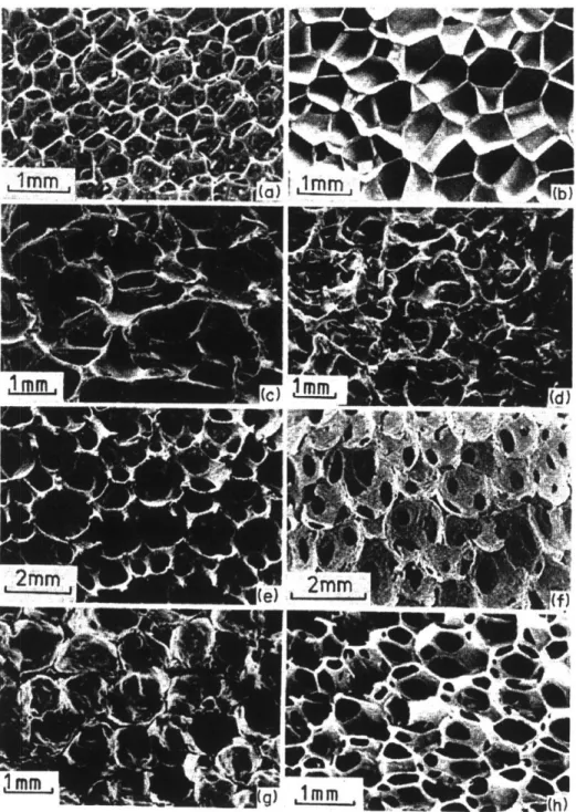
Man-made foams are typically honeycombs which are three-connected, that is, three cell edges meet at a vertex. Although these foams may contain some element of randomness which is visible as four, five or even higher numbers of sided cells, they still obey certain topological laws, and precise statements can be made about them. The same is true when studying the three-dimensional structures formed by these cells. Figure 1 shows a variety of three-dimensional cellular materials.
Figure 1: Three-dimensional cellular materials: (a) open cell polyurethane, (b) closed-cell polyurethane, (c) nickel, (d) copper, (e) zirconia,
(f) mullite, (g) glass, (h) polyether foam with both open and closed cells. (Gibson and Ashby, Cellular Solids, 1988)
Mechanics of foams
There are numerous articles in the literature on the mechanics of foams. According to Gibson et al, some of these are rather confused. Part of the confusion is attributed to the geometric complexity, part to lack of understanding of mechanisms involved. Recent work has helped to explain some of these mechanisms, and to develop a procedure which uses simple mechanics to create a model that is then tested by careful experimentation.
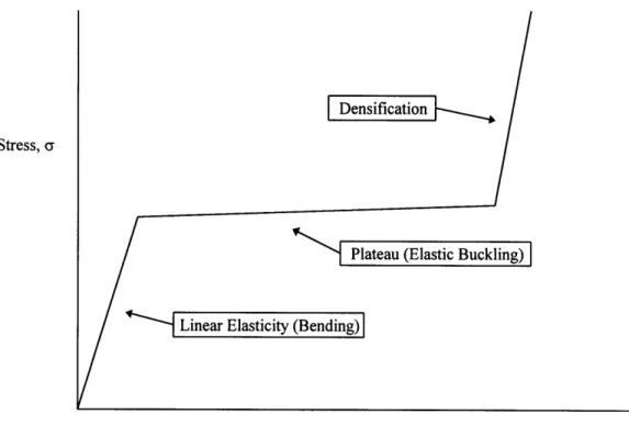
Figure 2, a schematic compressive stress-strain curve for an elastomeric foam, shows linear elasticity (bending) at low stress levels, followed by a plateau (elastic
buckling), finishing in densification in which the stress rises steeply.
Stress, a
Strain, 6
Figure 2: Compressive stress-strain curve for an elastomeric honeycomb foam.
Linear-elastic deformation
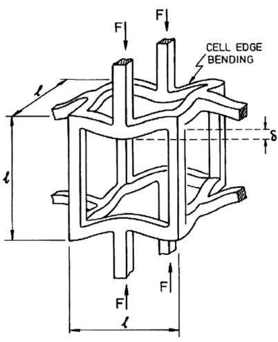
When a honeycomb foam is loaded in compression, it initially deforms in
a linear-elastic way. The cell walls bend, reacting to the compression force as a linear spring. The response is described by five moduli: two Young's moduli El* and E2*, a
shear modulus GI2*, and two Poisson's ratios, v12* and v21". The five are not
independent; the relation
El* v2 1" = E2* V12* (3.1)
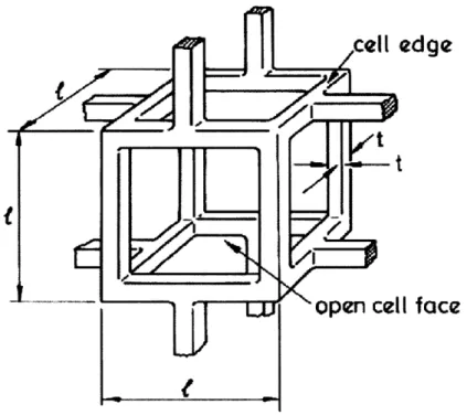
reduces the number of independent variables to four. Figures 3 and 4 show a model for an open-cell foam during linear-elastic deformation.
I
face
Figure 3: A cubic model for an open-cell foam (Gibson and Ashby, Cellular Solids, 1988).
Closed-cell foams have a significantly different behavior. When closed-cell foams collapse elastically, the fluid in the cells is compressed. If the initial fluid pressure in the cell is above atmospheric pressure, then this puts the cell edges under tension. Thus, the cell cannot buckle until the applied stress has overcome both the buckling load of the cell edges and this tension.
Fj
A
FT
4
Figure 4: Cell edge bending during linear-elastic deformation (Gibson and Ashby, Cellular Solids, 1988).
Non-linear elasticity, elastic buckling
The plateau in the compressive stress-strain curve is caused by elastic
buckling. Tests show that cell walls parallel or almost parallel to the load direction behave like an end-loaded column. End-loaded columns buckle when the load exceeds the Euler buckling load:
n2 2Efl
Pcrit = , (3.2)
h2
where n describes the rotational stiffness of the node where three cell walls meet, E is Young's modulus, I is the second moment of inertia of the cell wall and h is the height of the cell wall. There is a significant hysteresis loop associated with this state. To return to the linear-elastic behavior, significant amounts of stress have to be
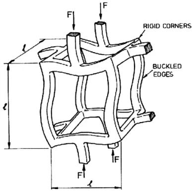
released. Figure 5 shows a model of an open-cell foam under buckling.
From the plateau in the stress-strain curve it is apparent that, once the material changes its behavior from linear-elastic deformation to non-linear-elastic buckling very, little additional force is required to continue deforming the material. This property was used as the basis for the controlled-compliance cushion, as well as for the active cushion.
AP
Figure 5: Elastic buckling in the cell walls of an open-cell foam (Gibson and Ashby, Cellular Solids, 1988).
Densification
At large compressive strains, at the end of the non-linear buckling, the opposing walls of the cells are crushed together, and the cell wall material is compressed. As this happens, the stress-strain curve rises steeply. The foam is considered to have
"bottomed out," becoming very stiff and losing its cushioning ability. The hysteresis associated with this behavior is not as significant as it is in elastic buckling, and therefore it is possible to proceed easily from one behavior to the other.
Foam selection
By examining the Gibson and Ashby model and Figure 2, the desired characteristics of a seating foam can be easily determined. Foam manufacturers do not rate their products in this way, though. As indicated by ASTM D 3574-95, Standard Test Method for Flexible Cellular Materials-slab, Bonded and Molded Urethane Foams, data available for a typical foam are the 25% and 65% IFD test results. This data, of course, does not give the required information on the linear elasticity and elastic buckling regimes.
Foam testing in Bridgeport
To obtain the information on the linear-elasticity and elastic buckling behavior of different foams, the following test apparatus was set up. Custom-made cushions were mounted on a Bridgeport milling machine, as described by Bush (1996):
The Bridgeport was programmed to move into the cushion at a constant speed until a predetermined point. As described in the SAE specifications for testing
foam materials, a 50 in2 indenter was used. Speeds in the range of 2 to 20 inches per minute, and pressures ranging from -1.0 to +0.5 psig were examined.
Applied force was measured using a "FORCE-5" digital force gage from Wagner Instruments. The gage is 100 lbf full scale, with 0.05 resolution, and gives a 0-1 volt analog output signal. The analog output was subsequently digitized using a 0-5 volt full-scale 12 bit A/D converter.
These tests yielded charts similar to that in Figure 2. It became possible to select a foam based on characteristics of its elastic deformation and buckling rather than on the IFD test results.
Our hypothesis was that it would be possible to control compliance of open-cell foam using vacuum or pressure. That is, by applying vacuum to an enclosed open-cell foam, the load under which the transition point from linear-elastic deformation to elastic- buckling could be changed. This hypothesis was proved to be correct, and was the basis for the variable-compliance seat cushion presented by Bush (1996).
4. Prototype Cushion
Controlled-compliance prototype
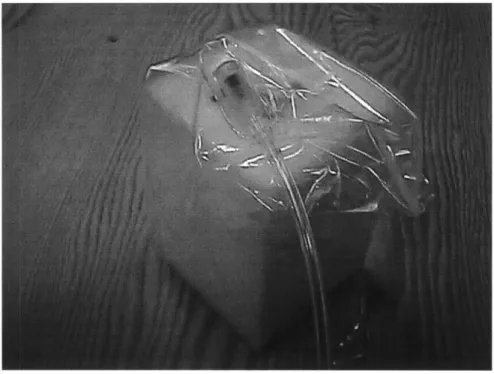
The controlled-compliance cushion was constructed based on the results presented in Section 3. A matrix of six by six cubes, covered in an air-impermeable fabric (Figure 6), is the basis for this cushion. Individual cubes were connected through tubing to form eight independent areas. A Labview-based controller allows variation of pressure/vacuum in each area.
The hardware associated with this system included two positive displacement pumps, two pressure accumulators, and four valves. In addition, each independent area required another two valves. By switching to an alternating bus system, it was possible to reduce the number of valves per area to one. Still, each zone had to be
individually controlled to get the best results, adding eight pressure transducers to the hardware needed.
Initially, two sets of cubes, in different grade foams, were constructed. The softer foam proved to be too soft, because it allowed the seated subject to bottom out. That meant the elastic-buckling range was exceeded, and the foam reached the top of the densification range on the stress-strain curve. The firmer foam, which at the time was the stiffest foam readily available, was also too soft. Most subjects tested still caused the foam to bottom out.
U
Figure 6: Covered foam cube, with tubing and fitting to allow control of pressure/vacuum.
The results of testing done with this cushion, using both an artificial buttock and a live subject, were reported by Bush (1996). Performance of the variable-compliance cushion was compared to its uncontrolled state and a slab-of-foam cushion. Results
showed that applying light (-0.1 psig) and moderate (-0.25 psig) vacuum can yield reduction in peak pressure of up to 20%. As promising as these results were, the cushion had major drawbacks: its weight, size, and the cost of the associated
hardware would make this a very expensive cushion. A new approach was required.
Passive prototype
The results from testing the variable-compliance cushion highlighted several
cells virtually eliminates the surface tension common in slab-of-foam cushions, allowing the cells to move independently, therefore allowing the cushion to adapt better to the user. Cells react according to the load they bear: i.e., with an appropriate foam, cells under low loads will be in the linear-elastic zone, while cells under higher loads will experience elastic buckling. This construction also reduces shear forces experienced by a seated subject.
Cells in the passive prototype are of the same construction as those in the active version. The foam cubes are covered with a urethane material with a vent at the bottom where the plumbing for the active cushion would connect. Uncovered foam cubes have a large friction coefficient when sliding against another foam cube. The lack of cover diminishes the cushion's effectiveness. Covered cubes are less exposed to liquids (spilled drinks or incontinence) which would shorten the foam's life.
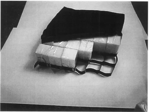
The cells in their current configuration (2.6125"x 2.6125" x 4.0"), are arranged in a six by six array. Foam currently used in the passive cushion (2560CFR) is supplied by Special Products Design, Columbus, Ohio. Cells are inserted into a polyurethane web which holds them in place. The web as well as the covers for the cubes are made by Dielectric Industries, Chicopee, Massachusetts, using different welding processes. An assembled cushion with cover, Figure 7, weighs only 2.5 lbs.
Figure 7: Passive cushion -retracted cover shows cells and support web.
Active prototype
All active seating systems mentioned thus far rely on positive pressure to inflate some
sort of bladder system. These bladders are supposed to lift the user, causing his/her weight to shift, unloading the ischial tuberosities. Using positive pressure, which usually results in large movements of the user, compromises the stability of a person sitting in the chair. Quadriplegics have little control of their movements and find instability quite threatening.
Periodic unloading of high pressure points, obviously, is the answer. But can it be done without disturbing the user's balance and sense of stability? Using vacuum it can, by collapsing the foam cubes to about 10% of the original size, relieving pressure in that area.
The cushion is the same array of six by six cubes of the same dimensions described for the passive cushion. Dividing the cushion into four zones, of five cells each, enables periodic pressure relief. Drawing vacuum on one zone will cause the cells to collapse and completely unload the areas previously supported by them. Since five cells are roughly less than 20% of the weight-bearing area, the movement experienced by the user is minimal. When one area is unloaded, the weight shifts to the rest of the cushion. Once the cell is exposed to atmospheric pressure, it will spring back to support the user. In its current configuration, pressure/vacuum is supplied through a manifold made of simple tubing and fittings (Figure 8).
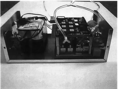
An ASF Thomas 5003 pump supplies air to the system. Two Pneutronics Series 11 three-way valves control the flow to and from the pump, allowing use of a single pump for pressure or vacuum. Air is then fed into a bank of four Pneutronics Series
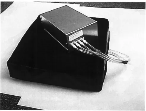
11 valves that control the flow to the different zones. A pressure transducer reads the vacuum/pressure in the manifold. This information is then fed back to a controller that determines if service is required to maintain vacuum/pressure within the set limits. Vacuum on the order of -2.0 psig is sufficient to cause the cells to collapse. The benefits from this part count reduction are significant. The weight and volume of the controller and hardware are reduced. Since there are fewer components, a smaller power source is required, which again helps save weight and volume. The complete package fits in a 10"x 6"x 3.5" box (Figure 9). It would therefore be possible to run this system for longer periods of time on an equivalent power source. Weight has been reduced to 7.5 lbs, which is comparable to a passive cushion such as Jay@or Floam.
Figure 8: Active cushion, cover retracted showing tubing.
Figure 9: Open controller box.
0--Figure 10: Complete system -cushion and controller box.
Figure 11: DEKA active cushion mounted on a power wheelchair.
28
--5.
Testing
Interface pressure measurement
Most pressure-sensing devices are designed to measure pressure at the cushion-skin interface while the subject is sitting on the cushion. Earlier devices consisted of air cell transducers. More recently, the design of pressure measurement devices has been improved and electrical transducers, whose measurements are based on changing resistive properties of the material with increased/decreased pressure, are used.
Air bladder-type transducers were once considered the most reliable pressure
measurement device. The technology for measuring air pressure is reliable and very repeatable. Air bladders measure peak forces, regardless of the orientation. That, in some cases, can be an advantage, but it does not allow for distinction between pressure and shear forces. Air cells are limited to static pressure measurement because of the pressure measurement method, which limits the scope of testing that can be performed.
Eckrich (1991) developed an array of pneumatic transducers to measure
dynamic pressure distribution. His device is intended to help understand the pressure changes a wheelchair user experiences as he propels a wheelchair. Each transducer is 0.7" thick and 1.25" in diameter. The array consists of 50 such transducers covering a total area of 7.5" x 15". Assuming the array can be doubled in size to cover the whole seating area (on average, wheelchair cushions are 16" x 16") without diminishing the system's performance, this system is not appropriate for measuring interface pressure between a wheelchair user and his cushion of choice as explained below.
same pressure they aim to measure. Some of these systems (as the one described above) require a special seat and cannot be used to measure pressure on a standard seat. Even the thinnest and most flexible of these devices is intrusive enough to alter the actual pressure. In addition, the relationship between the interface pressure and the actual pressure in deeper tissues is not known.
Palmieri et al (1980) compared sitting pressures on different wheelchair cushions using an air cell-type transducer and miniature electronic transducers. Twenty-one different commercially-available cushions were tested, including foam, gel and fluid-flotation cushions. The study found that both types of transducers yielded similar results, and the differences were determined to be statistically insignificant. Note that these results were obtained using simultaneous pressure readings; i.e., the air cell transducer measured the pressure on one ischial tuberosity and the electrical
transducer, the other. This seems to be in conflict with findings that show different (significant at times) pressures for right and left ischial tuberosities in seated subjects, and that sitting postures of live subjects are very hard to duplicate.
Reddy et al (1984) conducted an evaluation of transducer performance for buttock-cushion interface pressure. Again, this study evaluated pneumatic transducers as well as miniature electronic ones. They found that both types of transducers overestimated the nominal pressure calculated using the loaded surface area. They also found that the accuracy of the transducers was strongly dependent on the properties of the interface material, the relative size of the loaded area and the transducers. The interface pressure measurement between live subjects and cushions was found to correlate with subcutaneous interstitial fluid pressure measured with a wick catheter. Their work draws attention to potential inaccuracies that can occur when measuring interface pressure. It also suggests that with care, reasonable results can be obtained due to the compliance of human tissue under low strains, where the tissue helps to distribute the load evenly over the transducer.
Pressure measurement systems
Clinicians and researchers who are interested in interface pressure measurement have worked with industry to develop and test pressure-measurement systems. Many
systems have been developed, but not all have performed as expected. Of the two types of transducers discussed above, electronic transducers have been given a
significant amount of attention by different companies, leading to great improvement in performance. Four systems that have gained acceptance for routine clinical work are: FSA, made by Vista Medical; Pliance 16, by Novel; Seat Pressure Measurement
System, by Tekscan; and Xsensor pressure measurement system.
The FSA mat employs partially-conductive elastomers whose resistance changes as they are compressed. The resistance is a function of the surface area in contact, and of a change in microscopic texture that allows greater conductivity. Novel's pressure measurement system works with capacitive transducers, which, according to Novel, use a high-tech elastomer manufactured by Novel. The characteristics of this elastomer can be determined during the manufacturing process. Tekscan sensors utilize a proprietary conductive and semi-conductive ink. Again, the electrical resistance varies with applied force, and each intersection becomes a force sensor. Tekscan sensors stand out as the thinnest of all the systems mentioned above.
Evaluation of pressure mats
As one can see from the above-mentioned research, there are several systems that could perform the task of interface pressure measurement. An in-house evaluation of these systems was necessary to find a pressure-measurement device that would fit the needs. The manufacturers of the four systems were contacted, and their pressure-mapping systems were obtained for testing.
The mats were tested in a device, similar to that commonly used for calibration of pressure mats (Figure 12), consisting of two flat plates which slide into a structure
that limits their movement. Between the platens, the pressure mat and a flexible air bladder are placed. The air bladder is inflated to a desired pressure, which is checked
by a digital pressure gauge. The nominal pressure could then be compared to that
read by the pressure mat. Each system was tested for accuracy, reproducibility and stability.
Figure 12: Calibration device for pressure-mapping systems.
Novel's pressure mapping system appears very impressive, as are their claims for their system's performance. Yet, when the pressure mat was tested, its major
drawback made it unsuitable. Novel developed this system for other applications, and only later adapted it for seating-pressure measurement. Their technology limits the system's resolution to 0.1 N/m2 (= 0.145 lbf/in2 or 7.49 mm Hg), which may be adequate for general clinical assessment, but is not adequate for development of a new seating product. The Pliance 16 system has a 16x16 array of sensors.
The Xsensor pressure mapping system stands out as the most flexible and the least likely to interfere in the actual measurement. The cover material is smooth and slippery reducing the chances for a "hammocking" effect. This system has a 36x36 array of sensors. Its performance was not impressive. At a set bladder pressure of
100 mm Hg, sensors in the mat indicated pressures ranging from 80 to 120 mm Hg. The Xsensor system also exhibited a significant creep over time.
Vista Medical's Force Sensing Array, 15x15 sensors, is not as thin or as flexible as the Xsensor system, but the mat has a very flexible and slippery cover to offset the negative effect of its bulk. This system performed considerably better than the Xsensor. At a set pressure of 100 mm Hg, sensors read in the range from 90 to 110 mm Hg, with an average very close to the set pressure.
Tekscan's system is unique in that it has the smallest sensors, and therefore the largest number of sensors, in a mapping system. Its array of 42x48 sensors is thin and
flexible. In general, its performance can be ranked between the Xsensor and the Vista Medical systems, but some of its sensors were significantly off the set pressure.
All the systems tested exhibited creep in the first minutes of loading. The creep in the Novel system is masked by its poor resolution. Creep was observed in the other three systems as well. Readings in the Xsensor mat increased 25% on average in the first four minutes of loading. Creep in Tekscan and Vista Medical systems was significant in the first two minutes, and caused a change of 10% from initial readings. These results point out a major deficiency of current pressure mapping systems in measuring dynamic pressure.
Ferguson-Pell et al (1993) conducted an evaluation of pressure-mapping systems, performed in a similar manner and also including tests for "hammocking". Some important conclusions from this work are: Caution should be used when comparing measurements from different systems. "Hammocking" is also a problem with these
systems. The effect of "hammocking" on a measurement depends largely on the type of cushion used.
The DEKA Sitting Machine
Obtaining good interface pressure measurements, as seen above, is not as simple as seating a subject on a cushion and recording the readout. While the technology for doing this exists, it has some limitations. The creep phenomenon is a main concern. If the system requires two minutes to reach steady state, there can be no changes in the input during those two minutes. As testing with human subjects began, it became apparent that this requirement would be hard to work with. Most subjects wanted to squirm or shift their position within the first minute. Having to sit in an upright position made it more difficult still. In addition, human subjects tend not to sit in the same manner, even when it seems that way. A shift in pelvis position can change the pressure distribution, as can changes in head position, back angle, etc.
As a first attempt to solve this problem, a loader gauge designed to simulate buttock shape was obtained, Figure 14. This is the same device used by Ferguson-Pell et al (1993). This artificial buttock was constructed from plaster, with its inferior side covered with 15 mm-thick elastomeric gel (T-Gel, Alimed, Boston, Mass.). This was an improvement over using human subjects, because it was now possible to place the loader gauge on a cushion and allow the pressure mat to reach steady state.
This experiment brought two new issues to attention. First, the loader gauge was missing some key elements to make a good simulation of a human buttock. Namely, the loader gauge was almost flat on the bottom and did not have features that
resembled bony prominences. Second, it was difficult to prevent lateral motion as it settled into a cushion. This problem became more and more significant as the load increased.
The first issue was resolved by casting human subjects in plaster and using the negative to create a more authentic artificial buttock. Four different subjects were used for this purpose: three males (one of whom is paraplegic) and a female.
To simulate the bony prominences found in the buttocks, a plastic model (Anatomical Chart Co., Skokie, Ill.) of a human pelvis and femurs was placed in the mold. The exact location of the pelvis was determined with the help of the Physical Therapist, who examined the subjects. Soft tissue was simulated with Sun-Mate Foam-in-Place (Dynamic Systems, Leicester, North Carolina) foam. Figure 13 shows a negative buttock mold of a paraplegic subject. Figure 15 shows the foam-covered artificial buttock. The difference in contour with the first loader gauge, Figure 14 is obvious.
Figure 13: Negative mold of a paraplegic subject with plastic pelvis and femurs in place.
Figure 14: Gel-covered artificial buttocks.
Figure 15: Artificial buttocks made with Foam-in-Place and plastic pelvis & femurs model.
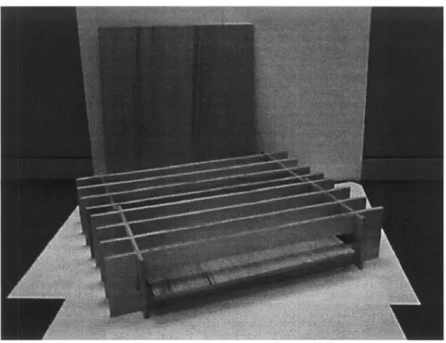
The second problem was solved by constructing a test apparatus that limits the lateral movement of the artificial buttocks. The DEKA Sitting Machine allows constant load to be applied to the test cushion in a repeatable way. The loader gauge is attached to
the bottom of a plate that supports a set weight. The loader and this plate are guided by a straight rod, which is constrained to move only vertically. The rod, weights and loader gauge can be mechanically lowered or lifted onto a cushion placed under the artificial buttocks.
Using the DEKA Sitting Machine, cushions can be tested for prolonged periods. It also allows a higher degree of consistency and reproducibility in the test. In Figure 16 the DEKA Sitting Machine is shown with an artificial buttock in place.
Cushion comparison
The DEKA Sitting Machine was used to perform a comparison of commercially-available cushions and the DEKA passive cushion. Using an artificial buttock from a paraplegic subject, and his corresponding weight, several cushions were tested. Cushions selected for this test were those considered by clinicians and users to be the best, most effective, or popular solutions. Some newer cushions that promise better performance, but have just been released, were included as well.
Most of these cushions were mentioned in chapter 2, but as a reminder, they will be categorized again. Foam cushions: slab-of-foam (HR45) is a common foam used for seating. Tempra Foam is also used as a slab, but foam properties are selected by a clinician for a specific patient after an evaluation of the patient's needs. Varilite
Figure 16: DEKA Sitting Machine with artificial buttock attached.
cushions are a combination of foam and fluid system. The cushion is covered with a material impermeable to air. A valve (or valves) allows the user to vary the mass of air in the system. Thus, air controls the overall shape and cushioning of the seat. Jay@, Floam and FloFit cushions use a combination of a hard base and a gel material, while Roho@ and Vicair cushions rely on a fluid system for cushioning. Varilite and Vicair offer different models based on the same principle. As a matter of interest in their different performances, two models of each were tested.
The test protocol called for a random order of testing within each series, to minimize the introduction of systematic errors. Interface pressure measurements were
performed with a Vista Medical Force Sensing Array. The pressure mapping system has a range of 0-200 mm Hg. To eliminate (as much as possible) the effect of creep in the sensors, as discussed above, the pressure was measured over a five-minute period. The figures presented correspond to measurement at the five-minute mark.
Areas subjected to high pressures are very likely to be the places where pressure sores develop; thus, peak pressures are a common metric when comparing cushions. To evaluate pressure distribution, figures such as the 9t or 8th decile, median, and total
loaded area are used.
Peak pressure results show a difference in performance between cushions. There are clearly two groups in this test. Cushions that performed significantly better include (average peak pressure in parentheses): DEKA Passive cushion (87 mm Hg), Jay@ (108 mm Hg), Roho@ (109 mm Hg), Tempra Foam (105 mm Hg), and Varilite ProForm (101 mm Hg). In the second group, performance was as follows: FloFit (149 mm Hg), Floam (159 mm Hg), HR45 (134 mm Hg), Varilite Solo (132 mm Hg), Vicair Positioner (145 mm Hg), and Vicair Twin (120 mm Hg). Peak pressures may vary over a significant range, as illustrated in Figure 17.
This clear distinction between cushion performances cannot be made as easily for the other parameters. The 9th decile results were, in ascending order: DEKA Passive
(62.00 mm Hg), Varilite ProForm (67.97 mm Hg), Varilite Solo (68.37 mm Hg), Jay@ (68.97 mm Hg), Tempra Foam (69.47 mm Hg), Vicair Positioner (69.50 mm Hg), Vicair Twin (69.03 mm Hg), Floam (72.90 mm Hg), HR45 (77.67 mm Hg), Roho@ (77.67 mm Hg), FloFit (79.87 mm Hg).
For the median pressure, Figure 18: Vicair Twin (39.17 mm Hg), Vicair Positioner (42.00 mm Hg), DEKA Passive (42.67 mm Hg), Tempra Foam (43.33 mm Hg), FloFit (44.33 mm Hg), Varilite ProForm (44.67 mm Hg), Floam (44.83 mm Hg), Varilite Solo (46.33 mm Hg), HR45 (49.33 mm Hg), Jay@ (49.67 mm Hg) and Roho@ (53.17 mm Hg).
The loaded area, Figure 19, is greatest on the DEKA Passive cushion (148 in2 ), followed by Vicair Twin (138 in2), Vicair Positioner (137 in2), and Varilite ProForm (136 in2). The next group had a slightly smaller loaded area: Varilite Solo (131 in2), Floam (131 in2 ), Jay@ (130 in2 ), FloFit (125 in2 ), HR45 (125 in2 ) and Roho@
(121 in2 ).
This comparison supports the assumption that a cushion in the proposed configuration has a number of advantages over conventional foam cushions, and even over other products currently available. As noted earlier, the importance of the passive cushion is twofold. First, it is essentially an active cushion in failure mode, proving that even in a case of a malfunction in the power or control systems, this cushions still more than acceptable. Second, the passive version can be used by wheelchair-bound individuals as their regular cushion. Experimental results indicate that the passive cushion performs as well as or better than the leading wheelchair cushions on the market.
200 180 160 140 120 U, 2 80 60 40 20 0
DEKA Flo Fit Floam HR45 Jay Roho Tempra Varilite Varilite Vicair Vicair Passive Foam Pro Solo Positio Twin
Form ner
Cushion
Figure 17: Average peak and 9th decile values (w/max and min data values) for tests of artificial buttocks in DEKA Sitting Machine.
80 70 60 50 40 0 30 20 10 0
DEKA Flo Fit Floam HR45 Jay Roho Tempra Varilite Varilite Vicair Vicair Passive Foam Form Pro Solo Position Twiner
Cushion
Figure 18: Average 8th decile and median values (w/max and min data values) for tests of artificial buttocks in DEKA Sitting Machine.
FloFit Floam HR45 Jay Roho Tempra Foam Varilite Pro Form Varilite Solo U Area Vicair Vicair Position Twin er Cushion
Figure 19: Average loaded area values (w/max and min data values)
for tests of artificial buttocks in DEKA Sitting Machine.
140 + 120 --100 -8so I-60 I 20+ DEKA Passive -"' -* - "' -'. aa "~ - "" m -' as "" - -** "" - "" 'm -"" - """' ' """'
Testing of active system
The DEKA active seat was tested in the sitting machine to check its ability to perform useful pressure relief. The set-up was similar to that used when testing the passive version. Using the sitting machine introduced above and the artificial buttock, the cushion was cycled through its pressure-relief algorithm for an hour at a time. The FSA pressure-mapping system monitored the interface pressure and its variations over this period.
Active seating systems, reviewed earlier, are marketed as pressure-relieving devices, but with an emphasis on use in stationary situations. Mobile versions are not always readily available, and do not seem to have been accepted in the market. Wheelchair users who require help with pressure relief use a tilt and/or recline wheelchair in conjunction with a passive cushion. Since Roho@ is the established market leader, it was decided to compare the active cushion to a Roho@, both in the sitting machine.
The issue of pressure relief through tilt and recline will be addressed in the clinical trial (Section 6).
As a first test, this was to verify that the system actually is capable of reducing pressure periodically under the peak pressure points. Our preferred interface pressure-measurement tool has a distinct drawback in this case. This was discussed above, when reviewing pressure-measurement systems. Pressure mats, as flexible as they may be, have difficulty following a highly-contoured surface. In these areas where the mat does not follow the surface, "hammocking" occurs, usually resulting in higher than actual pressure readings. The active cushion, without a doubt, is exposed to an extreme case of hammocking due to its mode of operation. Therefore, all pressure measurements in areas undergoing pressure relief are believed to be very "pessimistic."
Results
As expected, our results show a dramatic reduction in interface pressure in areas where pressure relief is being performed. Pressure under the bony prominences changes, over a cycle, from 95 mm Hg before the system is activated to a low of 42 mm Hg for the left ischial tuberosity. The right ischial tuberosity starts at 82 mm Hg and pressure in that area is reduced to 24 mm Hg during the cycle. It must be noted that, over a pressure-relief cycle, some areas will experience an increase in interface pressure. This happens because of the pressure redistribution that occurs when some of the support area is removed. Of course, this pressure increases only for short periods of time, and is eventually relieved during a cycle.
For comparison purposes, a Roho@ cushion was tested in the sitting machine.
Pressures under the ischial tuberosities were 99 and 115 mm Hg for the left and right ischial tuberosities respectively. This pressure remains constant unless relieved by a mechanical device such as tilt or recline. Pressure-mapping readings are presented in Figures 20-25.
G:\PRcycle.FSA
A
B
C D E
FGH
I
J
K L M N
O
1 0 0 0 0 0 0 0 0 0 0 0 0 0 0 0 2 0 0 0 0 0 0 0 0 0 0 0 0 0 0 03 0 0 0 0 16
4 0 05
2 13
6
0
7 0 8 0 9 010
11
12
13 0 0 07
00
0
00
0
0
0
0
0
0
0
0
0
0
0
0
0
14 0
0
16 0
0
13 0
0
0000O
13 0 0 1 0 00 18 9 0 0 0
0 13
13 0 0 0 00 5!
13 0 0 0 0 0 0 0 0 01 0
0
0
0
8
0
0
0
0
0
mmHg 00007 11:05:00.00 2/13/1997Figure 20: Artificial buttock on Roho cushion.
200 180 160 140 120 100 80
60
1415
G:\PRcycle.FSA
A B
C D E
FGH
I
J
KLMNO
0
0
0
0
0
0
0
0
0
0
0
0
0
0
0
0
0
0
0
0
2
0
0
0
0 17
00002 16:58:20.00 2/20/1997
Figure 21: Artificial buttock on DEKA active cushion before start of pressure
relief cycle.
4
9
10
11
12
13
14
15
200180
160
140
120
100
80
60
40
20
nnmmHg
IG: \PRcycle. FSA
AB
C DE
F GH
IJKLMNO
i --- 2002 0 2
0
Is
6 0
0
16110
606 80 0 100 960
0 840 110 60 12 00 1302 101 00 oIII 20 1400 000OO 1800 1500 O1 900 O OO000 ---mmHg 00003 16:59:30.00 2/20/1997Figure 22: Artificial buttock on DEKA active cushion, zone 1 pressure relief cycle.
G:\PRcycle.FSA
A B
C D E
FGH
I
J
K L M N
100000000000000 2 0 300 19 90 8 3 0 00519
5 11 0 12 2 0 0 0 13 0 0 0 0 0 000
5
0
0
0 0 27
0
0
0
0
*0
0
0
13
0
0
0
2
200 180 160 140 120 10080
60
mmHg
00004 17:01:45.00 2/20/1997 Figure 23: Artificial buttock on DEKA active cushion, zone 2 pressure reliefG:\PRcycle.FSA
A B C D E FGH
I
J
KLMN
O
1000
000
000
000
000
2 0 3 04
5
6
7
8
9
10
11
0
0
0
0
00
0
0
12 0 13 0 14 0 15 00VV
180 160 140 120 100 80 60 40 20 n mmHg 00005 17:04:30.00 2/20/1997 Figure 24: Artificial buttock on DEKA active cushion, zone 3 pressure reliefcycle.
G:\PRcycle.FSA
A
B C D E FGH
I
J
KL M N
0
0
0
0
0
0
0
0
0
0
0
0
0
0
0
0
0
0
00
0
0
0
mmHg
00006 17:07:05.00 2/20/1997Figure 25: Artificial buttock on DEKA active cushion, zone 4 pressure relief cycle.
200
180 160 140 120 100 80 60 40 20 0I..
_
6. Clinical Trial
Objective
While all laboratory testing yielded positive results, there is only one real measure of a cushion's effectiveness: its performance with live subjects. To determine if this real-life performance exists, a short-term clinical study was required. The study took place at the Faculty of Rehabilitation Medicine, University of Alberta, Canada. It was designed by Professor Al Cook (PI), Dean, and Professor Sharon Warren.
The clinical trial consisted of two parts: First, a test of DEKA active cushion comparing its performance with that of a Roho@ used in a tilt and/or recline wheelchair. Conditions to be met were:
* interface pressure measurement similar to or less than the Roho@ cushion. * no immediate onset of persistent redness in subject using the DEKA cushion.
The participants were six quadriplegics who routinely use a Roho@ cushion in a power wheelchair with tilt and/or recline, are at risk of developing a pressure sore, but do not currently have any sores. A clinician, who is a seating specialist, screened the volunteers prior to the test day and again on the day of the test.
After a skin inspection, interface pressure measurement was taken of each participant on his/her Roho@ cushion. The cushion was then replaced by a DEKA active
cushion and interface pressure was again recorded. The participants were then asked to remain seated for two 30-minute periods and one two-hour period. Participants were asked to engage in typical daily activities. At the end of each period, an inspection was performed to check for skin redness.
Clinicians recorded sitting profiles of the patients and interviewed them about their impressions of the DEKA cushion. Interviews were as open-ended as possible, to capture participants' perceptions regarding comfort, noise during operation, visual aspects, or any other impressions. Those who experienced no redness (all) were asked to return for a second day.
The second day of testing was to evaluate the failure mode of the cushion. After a skin inspection, participants switched to the DEKA active cushion. Interface pressure was measured, and participants remained on the active cushion for 30 minutes. If no redness was apparent, the cushion was deactivated and an interface pressure
measurement taken. During the 30-minute period of deactivation, participants were instructed not to use their tilt and/or recline function. Again, their skin was inspected after 30 minutes.
The second part of the clinical trial was to evaluate the passive cushion. Six paraplegic participants who regularly use a Roho@ cushion in a manual wheelchair were recruited. Conditions to be met were:
* there must be a similar or lower interface pressure when using the DEKA cushion.
* there must be no immediate onset of persistent redness in subjects when performing their usual pressure relief.
Testing procedures were the same as those used the first day with the active cushion. Participants were inspected before the test to check for existing pressure sores. Interface pressure measurements were taken while they were seated on Roho@ and DEKA cushions. Participants were then asked to engage in typical activities for two 30-minute periods and one two-hour period. Participants were instructed to perform pressure relief as usual. As in the previous test, skin inspections were performed between those periods.
Results
DEKA active cushion
Clinicians' evaluation of the subjects: Of the six subjects who participated in the test, not one developed a pressure sore. One subject had some persistent non-blanchable redness that resolved within 15 minutes after the first 30-minute period. The same
subject had no redness after the second or third periods on the cushion. Another subject had not developed any redness after the first period, but had some persistent non-blanchable redness after the second 30-minute period. This resolved within five minutes and no redness was detected after the two-hour period.
During the second day's test only one participant showed any redness after either period. The participant who did, had slight redness over his right ischial tuberosity
after sitting on the deactivated cushion for 30 minutes. The redness resolved within three minutes. Figures 26-31 compare interface pressure readings for one subject on
his Roho@ cushion and on the DEKA active cushion.
Participants' comments on the DEKA cushion were mostly positive. It was noted to be more stable than their usual Roho@ cushion. Other differences were the height of the cushion (the DEKA cushion is about 4"; the Roho@ 3"). Most participants were surprised at the low noise level of the hardware, and only one commented that the current noise level would bother him.
DEKA passive cushion
Clinicians' evaluation of the subjects: Of the five participants (one was not able to participate), none developed a pressure sore. One subject developed non-blanchable redness after each of the sitting periods, all of which resolved within ten minutes. All other subjects had no signs of redness during any of the skin inspections.
G:\PRclinical.FSA
A B
C D
E
FGH
I
J
K L M N O
1200
000
1
0
0
0
0
0
4
0 1 13 9
13 0 2 17 10 8 10
6
3
8
8 0 0 2 147 17
0 0 0 0 7 11
5
16 17
12 0 0 0 2 200 180 160 140 120 100 80 6040
20
14 015
0
9
10 10
5
5
0
0
5
16 17 8
0
0
0
0
0
9
0
0
mmniHg
00007 14:17:01.90 11/30/1996Figure 26: Subject 4 on Roho cushion.
3
C---G:\PRclinical.FSA
A B C D E FGH I J KL M N1
2
0
2 0 0 3 0 0 4 0 0 5 0 0700
8 0 11
9
0
0
10 0
0
11 0
0
12 0
0
13 0
0
14 0
0
15 0
2
mm-ig
00006 14:23:39.23 11/30/1996Figure 27: Subject 4 on Deka cushion non-activated.
IEF. ia-j i j J 0