Software Product Lines Composition through
Partial Derivation
Amina Guendouz
C.S. department, Saad Dahlab University, Blida, Algeria E-mail: guendouz.amina@yahoo.fr
Djamal Bennouar
LIMPAF Lab, Bouira University, Algeria E-mail: djamal.bennouar@univ-bouira.dz
Received: 31 May 2017; Accepted: 01 July 2017; Published: 08 October 2017
Abstract—Software product line approach has been successfully adopted in various software domains. In some fields, single SPLs are no longer sufficient to fulfill their requirements due to the large variability amount they include. Consequently, a set of separated SPLs is built to handle this issue and construct what is known by Multi Product Lines (MPL). However, the emergence of MPLs results in several challenges, namely: managing the reuse between SPLs, structuring the MPL model and distributed derivation. In this paper, we propose a new approach for SPLs composition. Our approach relies on two main concepts: the separation of concerns and the partial derivation. It is validated in the context of an e-Learning MPL and an illustration is explained throughout the paper. The results show that our approach helps systemizing reuse within MPLs and structuring the MPL model. Moreover, SPLs are integrated early in the development process avoiding thus the distributed derivation challenges.
Index Terms—Reuse, Multi Product Lines, Software Product Lines, Partial Derivation, Composition.
I. INTRODUCTION
Reuse has been always a crucial interest of software engineering. One of the most promising reuse approaches is Software Product Line (SPL). SPL approach systematizes reuse within a particular field by predicting potential reusable components, designing them to be easily adapted to several contexts, and making them available to be reused by final applications. This results in faster production processes with lower cost and effort of development. Nowadays, single SPLs are no longer sufficient to manage variability in some large fields due to their complexity and broadness. Consequently, several separated SPLs emerge focusing each one on a particular subfield what is known as Multi Product Lines (MPLs).
MPL approach allows focusing on each subtopic of the MPL domain separately and thus provides customers with more specialized applications. However, adopting an MPL approach without planning for inter-SPLs reuse
results in losing the reuse information among the SPLs of the MPL. Reuse between applications involves adapting the components to the new contexts. Reuse among SPLs is even more complex than it is between applications. An SPL encompasses various contexts, thus reusing a component by an SPL involves its adaptation to the set of contexts it includes and this results in multiplying the cost, time and effort of development. Moreover, when reusing several components, the whole process is repeated accordingly. Consequently, reuse among SPLs of an MPL is a complex and laborious operation, and solutions are needed to help systematizing the reuse in MPLs environments.
In this paper, we tackle three main challenges encountered by MPL engineering which are: structuring the MPL model, managing reuse across separated SPLs and distributed derivation. We first report on challenges encountered by MPLs development then we propose a new approach allowing reuse management within MPLs. Our approach lies on the separation of concerns and the partial derivation concepts. Components to be reused by a set (or all) of MPL SPLs are produced by specialized SPLs. Those latter are partially derived and composed early in the development process avoiding thus several MPLs challenges. We focus in this paper on the partial derivation of SPL architecture. The proposition is validated for the e-Learning field. In fact, e-Learning will present an example on which we illustrate the various concepts of our proposition along the paper. Our contribution is then twofold; it can be of benefit to software engineers as well as to the product line and reuse community. We provide a method for structuring the MPL model and managing the reuse between SPLs. In addition, we describe techniques that allow preparing SPLs for early composition in the MPL development process.
The paper is structured as follow: section 2 introduces the basic concepts for the studied research field, including: SPLs, MPLs, Component Based Product Lines (CBPLs) in addition to the e-Learning MPL. Section 3 comments on the related work. Section 4 presents our proposition illustrated by the e-Learning MPL case study. Section 5
presents a validation case study and section 6 discusses the obtained results. Finally, section 7 summarizes the paper and discusses future work.
II. BACKGROUND
In order to clarify the research field of the paper, we present in this section the main concepts related to the studied issue. We first define MPLs and discuss their crucial challenges, then we present the CBPLs modeling approach adopted in this work and, finally, we introduce the context of our research work.
A. Multiple Product Lines
An SPL is “A set of software-intensive systems sharing a common, managed set of features that satisfy the specific needs of a particular market segment or mission and that are developed from a common set of core assets in a prescribed way” [1]. SPL approach aims to systematize reuse throughout all the software development process: from requirements engineering to the final code and test plans. The purpose is to reduce time and cost of production and to increase software quality by reusing elements (core assets) which have been already tested and secured. These objectives can be realized by putting in common the various development artefacts, such as: requirement documents, design models, architectures, code (reusable components) and procedures of test and maintenance. Hence, SPL Engineering (SPLE) relies on a fundamental distinction between development for reuse and development with reuse [2] [3]. Domain engineering or “development for reuse” consists in developing the reusable elements (core assets) through the domain analysis, domain design and domain implementation processes. The main outputs of this process are: identification of SPL members (scoping) and extraction of similarity and variability between them. Application engineering or “development with reuse” consists in developing the final products, using core assets and specific requirements expressed by customers. This process is similar to the traditional development process; however, each step is facilitated by reusing the outputs of the first process.
Instead of the significant benefits they bring to software engineering, single SPLs are no longer sufficient in some environments due to the emerging of reuse across several interdependent SPLs what is known as Multiple Product Lines (MPL). An MPL is defined as a set of several self-contained but still interdependent product lines that together represent a large-scale or ultra-large-scale system [4]. A crucial reason for introducing MPLs is the need for separating between several business purposes including different sets of commonalities and Variation Points (VPs). A more focused SPL scope allows stronger constraints on variability [5]. MPLs may also facilitate assets creation, in contrast to generic assets that are hard to develop and maintain. Yet, MPLs emergence has given rise to several challenges for SPLE:
The distinction between SPLs within the same field results in losing the reuse information between them.
MPLs need, then, to manage the reuse across the several SPLs they include [4] in order to reach larger scale reuse. Two solutions are conceivable: the direct inter-SPLs reuse or the development of a broad SPL including all the MPL subfields. If developers choose the direct reuse between separated SPLs they have to adapt components to fit the new requirements. This will draw them back to the problem of unplanned reuse. In this case, adaptations are limited and make the developers’ work laborious and error prone, this may push them to prefer developing components from scratch. Otherwise, developers may choose to systematize reuse between the separated SPLs by developing one SPL covering the whole MPL domain. This will result in a broad SPL covering several MPL subfields and thus several business purposes. However, numerous problems can arise from broadening the SPL scope [6], mainly: decreasing complete commonality (common components to all products) and in return increasing partial commonality (components common to a set of products), over-engineered SPL architecture and hard variability management due to the increased complexity of the SPL. Consequently, efficient methods are needed to manage inter-SPLs reuse within MPLs environments.
Current MPLs tends to compose SPLs components at derivation time. So, instead of dealing with a single SPL derivation, developers must choose components to be reused from other SPLs, adapting them to the current reusing context and integrating them with the reusing application. This integration way known as distributed derivation [4] results in several problems. Reused components that are already developed using particular modeling and implementation techniques must be adapted to fit the new application requirements. Components to be reused must suit to not only one reusing product but to various products included in the various reusing SPLs. This results in multiplying the adaptation processes and thus delays the derivation and increases the costs and time of development. In addition, choosing the right reusable component from several competing SPLs is itself a problem that needs a decision process to be resolved. Furthermore, the integration activity may require reviewing the whole reusing SPL architecture, or imply important adaptations for the reused components. Consequently, the distributed derivation is a hard and laborious task to perform.
MPLs are hard to be managed using a single model due to their size and complexity [4]. Thus, the MPL model needs to be decomposed into several models that can be managed efficiently by separated teams. Techniques are then needed to decompose the MPL model into small units more likely to be managed easily. Yet, dependencies between SPLs models must be considered since they belong to the same field and represent together a large-scale system. Those dependencies are involved thereafter to ease the composition of the MPL’s SPLs in order to obtain a complex system. Yet, SPLs composition approaches within MPLs are still immature [4].
In the next section, we propose an approach that benefits from MPLs advantages and aims to overcome
the before-discussed problems.
B. Component Based Product Lines
CBPL engineering has been introduced to overcome the lack of maturity in SPLE by unifying the strengths of two complementary approaches: SPLs and Component-Based Development (CBD) [7]. CBD is a reuse based approach for defining; implementing and composing loosely coupled independent components into systems [8]. It is used to ensemble software from existing components [9]. CBD supplies technologies for reuse in the small, while SPL approach intends reuse in the large. Putting them together allows reaching large scale reuse and flexibility at the same time. However, only few works have been done in this area, we distinguish among others: KobrA [10], koala [11] [12] and IASA extension [7]. In this paper we adopt the approach that has been proposed in our previous work [7].
Guendouz and Bennouar [7] Extend the component-based model IASA (Integrated Approach to Software Architecture) [13] in order to allow variability modeling. IASA was used to realize complex e-Government software systems, and was proved as a clear and easy specification language to design at a high level of abstraction using Aspect Oriented approach [14] [15]. IASA aims to provide the models and tools which have the ability to directly capture the architect’s mental model about a solution in the early step of a software elaboration process [16]. Hence, IASA architecture model of an SPL can be easily deduced from its feature model if this latter has been constructed considering composition links between features. Mapping the feature model to the architecture model increases the possibility of automating the development process thereafter.
The IASA approach supports the Aspect Oriented Software Architecture (AOSA) specification through the distinction between two components kinds: aspect components and business components [16]. IASA allows the use of any component as an aspect component and any aspect component as a business component. Moreover, aspect components are not limited to represent technical concerns; they may be extended for other concerns such as Graphical User Interface (GUI).
The extended IASA [7] supports both composition and variation. Composition is maintained through basic IASA concepts while variation is supported by the extended IASA concepts. The design according to IASA approach uses a component-oriented process which proceeds by successive refinement. An IASA component is seen from the outside as a black-box that communicates with the external world through Ports [16], which define the services it can provide or require. The internal view of a primitive component is inaccessible, while the structure of a composite component is well defined, it consists of three parts: Operative Part, Aspect Part, and Control Part. The Fig. 1-a sets out the basic IASA notations.
The extended IASA [7] allows modeling variability at components as well as architecture levels; this is ensured by introducing the concepts of variable components and variable connectors. IASA extension represents
variability as follow:
All of components and connectors may be annotated by: «Mdr» and «Opt» which means respectively: Mandatory and Optional.
We distinguish between four interfaces kinds: mandatory provided interface, mandatory required interface, optional provided interface and optional required interface as depicted in the Fig. 1-b.
A component that has a variety of implementations is represented by: component choice as shown in Fig. 1-b.
The relationship between a component and a variable set of components is materialized by: Connector choice. Such as the number of components related by the connector is specified by a cardinality interval [n, m] where n, m ϵ N and m ≥ n, such as: n = m if the type of the relation is AND; m ≥ n if the type of the relation is OR;
n = m =1 if the type of the relation is XOR or Alternative.
Name_Cmp
Name_Cmp Provided interface Required interface
Internal view of IASA components
a. IASA basic notation Connector
Pointcut Component External component
b. Variabiliy Extensions of IASA
Mandatory provided interface Optional provided interface Mandatory required interface Optional required interface
Component Choice Connector Choice «Choice» :Component_ Cmp :1_Cmp :2_Cmp :n_Cmp Operative Part (Business components) Aspect Part
(Tra ci ng, Logging, Excepti on)
Control Part (Controller) «Choice» :Connector_Cnt [n..m] «type» :1_Cmp «type» :2_Cmp «type» :m_Cmp :Component_ Cmp
Fig.1. The IASA notations.
C. The E-Learning MPL
Our approach has been actually inspired by our experience in developing SPLs for e-Gov field in context of the project “Towards an SPL for e-Government applications”. The project was launched in January 2014 by LIMPAF Laboratory at Bouira University, Algeria. The project aims to set up the technological and methodological bases to the development of an e-Gov product line. The objective of this product line is the fast production of software intended to the different Algerian government institutions (Administration, Justice,
e-Voting, e-Meeting, e-Health, e-Education, etc.). The produced software should be compatible to ensure a high level interoperability between the various government institutions. However, building a single SPL for the whole domain is infeasible due to its broadness and complexity. Therefore, a set of separated SPLs has been built and each of them intends a particular e-Government subfield, this results in an e-Government MPL. Nevertheless, those SPLs must preserve interoperability and reuse information must be kept between them in order to get faster development processes and lower costs and development effort. In this paper we consider a sub-set from the Government MPL which are the e-Learning SPLs (e-University, e-Secondary, e-Primary, and e-PrivateLearning) to illustrate the proposed approach. The e-Learning case study is used throughout the paper to illustrate and validate our proposition.
III. RELATED WORK
Only few works have been proposed to solve the problems encountered by MPLs engineering. In this section we report on the main propositions and we comment on them.
Rosenmüller et al. [17] have altered the MPLs structuring problem. They propose to extend the feature model with explicit modeling of SPLs instances. The matter is to allow configuring an SPL using multiple instances of another SPL. In another work, Rosenmüller et al. [18] added the notion of composition model aiming to automate the configuration of MPLs. A composition model integrates multiple SPLs by describing for each SPL which instances of the other SPLs it uses. The work seeks to describe the implementation of MPLs on an abstract level basing on the involved SPL instances. However, when several SPLs and instances are involved in the composition process it became hard to manage at the same time three abstraction levels: MPL, SPL and SPL instances. Moreover, SPLs instances integration produces the problem known by distributed derivation (section 2.A) especially when numerous SPLs instances are needed for the composition of an SPL.
Schröter et al. [19] [20] introduce multi-level interfaces to guaranty the correct collaboration between multiple SPLs. They distinguish between four interfaces: variability-model interfaces, syntactical product-line interfaces, behavioral product-line interfaces, and non-functional property interfaces. Those interfaces aim to detach the direct dependency between SPLs and to enable modular analysis of MPLs correctness. They are defined as follow: - Variability-model interface: is a specialization of the reused SPL’s variability model - Syntactical interface: represent a view of an SPL’s reusable code artefacts without implementation detail - Behavioral interface: is an agreement on the behavior of different methods - Non-functional interface: represent non-functional properties of an SPL that other SPLs use.
Apparently, the introduced interfaces represent views on what could be reused from an SPL within an MPL. They are defined as collaboration means between SPLs of
an MPL. Authors do not mention how the interfaces are realized or how one SPL is reused by another one.
Herman and Tim [21] propose to combine feature model with context variability model to model MPLs supporting several dimensions in context space. They use stage configuration to generate specialized feature models. The Context Variability Model captures the commonality and variability of the context. The context is the environment in which a product resides. The Context Variability Model is combined with a conventional feature model to create an MPL-Feature model. However, this model needs more work at domain engineering stage and must be maintained over all the development process. Rabiser et al [22] present an approach that aims to improve awareness during MPLs derivation such as users configuring a system are informed about the decisions made in other systems. The approach is materialized by a decision board that allows users to publish their decisions and subscribe to other projects decisions. The paper in fact presents a simple approach to communicate the key decisions in multiple SPLs derivation processes without explicitly integrating the underlying variability models. So it does not present a solution neither to the inter-SPLs reuse within MPLs nor to the MPLs model structuring challenges.
Dhungana et al [23] propose an approach that organizes an SPL into a set of interrelated model fragments describing the variability of particular parts of the system. Model fragments help structuring the modeling space and provide support for evolution. This work is important in terms of structuring the modeling space and merging models. The proposition is actually targeted to single SPLs environment, yet in MPLs environments decomposing the system into fragments that define reusable assets is not enough for managing complexity. Moreover, the work has no relation with variability management across MPLs which is a crucial issue tackled by our work.
IV. SPLS COMPOSITION
SPLs composition process consists in three main steps: separation of concerns, partial derivation and composition as depicted in the Fig. 2. Separation of concerns step decomposes the MPL into two SPLs kinds: MPL sub-SPLs and crosscutting sub-SPLs. Partial derivation activity aims to prepare the crosscutting SPLs to be integrated with their reusing SPLs, while SPLs composition results in complete SPLs ready to be derived using traditional methods in order to produce final applications.
A. Separation of Concerns
As stated before, the MPL model needs to be well structured to allow better variability management across their SPLs. If we analyze existing MPLs we find that their sub-SPLs share some commonalities even if they are separated. Considering for example the set of e-learning SPLs, we find that e-Learning applications can be implemented in a variety of settings: for schools and universities to complete or enhance classroom learning,
for corporations to provide training and certification for their employees, and for organizations to provide e-Learning courses to a larger learners population virtually anywhere in the world. Each e-learning subfield encompasses various applications that are characterized by common and variable features. For instance universities produce applications for the various faculties that may include variable courses and interaction tools as well as different tests and exercises kinds. Therefore, separated SPLs can be built for the various e-Learning sub-fields: University, Secondary, Primary, e-PrivateLearning SPLs. However, all of those SPLs still have in common some crucial features such as: security, GUI, user management, document management, evaluation and search.
Fig.2. SPLs composition process.
In order to structure the MPL model, we propose to separate between features that are common to all (or a set of) MPL SPLs and those that are specific to each sub-SPL (intended to the basic business sub-field functionalities). We see the common features as crosscutting concerns for the MPL, since they reply to transversal needs for a set or all MPL SPLs. Yet, even if crosscutting-features are common to some (or all) sub-SPLs they still may vary in their sub-features and their reuse requires adaptations to fulfill the new needs. Thus, crosscutting-features can in turn be derived themselves from dedicated SPLs that we call: crosscutting SPLs. Separation of concerns at SPLs level helps structuring the MPL models. We distinguish between two kinds of models: the MPL sub-SPLs models and the crosscutting SPLs models. The integration of those SPLs is discussed in the next sections.
Crosscutting SPLs aim, on the one hand, to systematize reuse throughout the various MPL SPLs by defining the MPL crosscutting-features, and devoting an SPL for each of them. On the other hand, SPL development often gives more emphasis to business functionalities. Ignoring secondary (especially technical) functionalities decrease the systems’ performances, given that a weakness in the SPL design can cause problems throughout all its members. Improving these functionalities is one of crosscutting SPLs’ advantages. Since they will be created by specialized developers and tested in different contexts; crosscutting SPLs will provide the MPL by high quality components which will participate in improving the derived applications’ quality. In addition, the MPL SPLs
development processes will be simplified by reusing the core assets derived from the crosscutting SPLs.
Crosscutting SPLs are defined by analyzing the MPL sub-SPLs (if they exist or the MPL subfields) and extracting the main common features among them. Hence, all of GUI, evaluation, user management, security SPLs represent crosscutting SPLs for the e-Learning MPL, while: University, Primary, PrivateLearning, e-Coaching are the sub-SPLs of the e-Learning MPL. For instance: the evaluation crosscutting SPL aims to provide various test kinds to evaluate the learners' understanding for the provided online courses. Yet, the evaluation components needed for primary applications differ from those needed by an e-University SPL. E-University applications require more advanced test types, such as: allowing diagrams design, supporting more languages and special mathematics symbols. In contrast, the evaluation component may not be needed in other contexts such as a Self-paced learning SPL.
B. Partial Derivation
Partial derivation is a transformation procedure that takes as input the core assets of an SPL to be reused (crosscutting SPL) and generates a partially derived SPL ready to be integrated with its reusing SPL (MPL sub-SPL). Partial derivation consists in modifying a set of VPs included within the reusable SPL’s core assets in order to fit the reusing SPLs’ requirements. Ultimately, the partial derivation can alter a set of VPs or in some cases all the SPL VPs may be modified to meet the new needs. As we will have a full SPLs composition (not only the code is composed), all artefacts types to be composed must be partially derived from requirements models to the architecture and implementation code. The set of partially derived artefacts will be completely derived thereafter as a part of the reusing SPL.
Partial derivation is comparable to the specialization concept that was introduced by Czarnecki et al [24] [25]. They define specialization as the transformation process that takes a feature diagram and yields another feature diagram, such as the set of configurations denoted by the latter diagram is a true subset of the configurations denoted by the former diagram. Successive specialization processes result in a final configuration, this method is called staged configuration [24]. Specialization defers from partial derivation in two crucial ways. On the one side, the purpose of introducing specialization is to allow handling applications derivation through several configuration stages what is needed in the case of software supply chains. Final applications derivation step is then decomposed into several specialization stages each one is performed by a particular actor, whereas partial derivation aims to prepare the reusable SPLs for integration with the reusing SPLs during the domain engineering phase. On the other side, specialization is defined to be applied particularly on the feature models what is clear from its definition, while partial derivation is applied to all the artefacts extracted from the reusable SPLs domain engineering (including requirements models, architecture and final code).
Unlike specialization, the resulting model from a partial derivation procedure does not describe necessarily a sub-set of the systems set described by the original model. In some cases, the partially derived model is extended by adding new functionalities or VPs to fulfill the particular needs of the reusing field. This is due to the fact that the resulted model is integrated with the entire reusing SPL (with all its covered contexts) not a particular final application. We can then distinguish between two partial derivation categories: restriction and expansion techniques. The partial derivation of a model can include transformations from both categories.
Restricting a model means altering the model in a way that restricts the choices set covered by the resulted model. The set of transformations that could be done in this category are: - to restrict a choice VP - to change a VP type from optional to mandatory - to restrict an attribute by assigning a value - to omit a VP or a feature (eventually a component).
Expanding a model means to modify this model in such a way that expand the choices set covered by the resulted model. The set of transformations included in this category are: - to extend a choice VP – to change a VP type from mandatory to optional – to add a VP or a feature (eventually a component).
Those techniques are applied to all the artefacts types of an SPL. In this paper we focus on the partial derivation of the SPL architecture. Hence the partial derivation techniques are illustrated basing on the architectural model “IASA extension” (see the section 2.B).
Restriction Techniques:
● Restricting a Choice VP: A choice VP allows
several configuration possibilities unlike optional and mandatory VPs that allow only two resolution possibilities. It describes the variation of a set of related elements and may limit the options by a cardinality interval. Restricting a choice VP means reducing the configuration possibilities enabled by the VP. This can be done by removing an option or an options-set from the elements described by the VP or by reducing the related cardinality interval. For the architecture model we distinguish between:
1. Restricting a choice component by removing one or several implementation possibilities. A special case of this operation is when no implementation choice is left. As a result, a choice component with no implementation is completely removed from the architecture.
2. Restricting a choice connector by excluding a component or a set of components from the choices related to the connector. If the components group size is s and its cardinality is [n, m] such as
n ≤ s, when removing one grouped component the
new components group size will be s - 1 and its
new cardinality interval will be [n, min(m, s-1)] where min(n, nʹ) takes the minimum of the two natural numbers n and nʹ. Special cases occur when it remains a single component from the components choices set or when no component remains. If no component choice remains then the connector is no longer useful and it must be removed from the architecture. If the connector is related to a single component and the cardinality interval is [1, 1] the choice connector is replaced by a mandatory connector. In the case of [0, 1] interval, the relation choice connector is changed into optional connector.
3. Restricting a choice connector by reducing the choices number described by the interval. A choice connector with cardinality [n, m] may be reduced to [nʹ, mʹ] where nʹ ≥ n and mʹ ≤ m. Special cases occur when getting [1, 1] or [0, 0] intervals. If we obtain [1, 1] interval and the connector is related to more than one component, the connector type is called Alternative. If we obtain [0, 0] interval, the connector is completely omitted whatever is the number of components it is related to.
● Changing a Variability Type from Optional to
Mandatory: A functionality may become obligatory for particular reusing contexts. For the architecture model, an optional component may be changed to mandatory type if its existence is obligatory in the final reusing applications. This is also valid to both of optional interfaces and connectors.
● Removing a Functionality: A restriction operation
may be done by removing a functionality. In architecture model we may: omit a component with all its interfaces and connections, omit a particular interface from a component, or omit a connection between two components. Omitting a component from a component-group and omitting a set of components cases correspond to what is described by restricting a choice VP.
Expansion Techniques:
● Extending a Choice VP: It means increasing the
configuration possibilities enabled by the VP. This can be done by adding an option or an options-set to the elements described by the VP or by extending the related cardinality interval. For the architecture model we can distinguish:
1. Adding a new implementation (or a set of implementations) to the implementations group of a choice component. A component with a single implementation may turn into a choice component if new implementations are introduced;
2. Adding a component or more to the components choice group related to a choice connector; 3. Extending the options number interval described
by a choice connector. The choice connector cardinality interval [n, m] may be extended to [nʹ,
preserved (nʹ ≥ 0 and mʹ ≤ s). A simple connector may change into choice connector if it must be related to more than one component.
● Changing a Variability Type from Mandatory to Optional: A variability type may be changed if needed by the reusing SPL. A mandatory component may become optional and this results in extending the configuration possibilities of the model. This is valid also for mandatory interfaces and connectors. The IASA extension architecture style allows dealing with each variable architecture element separately which allows more complete and explicit variability representation.
● Adding a Functionality: In the case of specific new requirements by the reusing SPL, the reused SPL can be extended by new functionalities. An architecture model can be then, expanded by adding a new component or a component set. Related interfaces and connectors are changed or added accordingly. Moreover, new interfaces and connectors may also be added to the model if needed. The cases of adding new component implementations or extending connector cardinality are described by extending a choice VP.
C. SPLs Composition
SPLs composition means the integration of the crosscutting-SPLs that have been partially-derived to be reused by a particular domain with the SPL of this domain. This operation takes as input an MPL sub-SPL in addition to the partially derived crosscutting-SPLs for this sub-SPL and yields an SPL ready to be completely derived to produce final applications. SPLs composition can be performed simultaneously with the sub-SPL domain engineering, such as each partially-derived artifact is merged with its correspondent reusing artifact at development time. Yet, SPLs can be integrated subsequently since the crosscutting-SPLs core assets base is available for reuse.
Sub-SPLs must plan for reuse in order to decrease the risk of encountering integration challenges. Moreover, the used languages are recommended to be compatible in order to ease the integration step, yet they could be adapted using a unified language, for example, before integration. Several works have studied the merging of SPLs models: Morin et al. [26] [27] present an approach to safely integrating aspects models with variability into existing models. Abele et al. [28] provides an overview on a variability management tool called CVM framework. Among other capabilities, the tool allows composing feature diagrams from several related SPLs. Alférez et al. [29] propose the Variability Modeling Language for Requirements (VML4RE), a multi-view composition language for SPL requirements. VML4RE language supports the composition of elements defined in separate and heterogeneous requirement models using a set of operators. Dhungana et al. [30] present an approach to facilitate variability models integration. They provides a unified perspective to users configuring products in multi product line environments, by making the internal technical aspects of using variability models for
configuration transparent to the stakeholders performing the configuration.
Reused components concern generally particular functionalities from the reusing SPL. Those components are represented by black boxes that will be replaced by partially-derived components thereafter. We suggest differentiating those black boxes components by annotating them in the architecture model by «CC_cmp» (i.e. CrossCutting SPL component). During the partial derivation step, the crosscutting components are extracted from the crosscutting SPLs according to the reusing SPL requirements. Only needed interfaces and sub-components are kept. At composition step, the CC_cmps are replaced by the partially derived components and connections are performed to link the reused components with the reusing SPL reference architecture components. The CC_cmps may represent aspect components or business components to the reusing SPL architecture. However, this does not influence the composition operation. For instance, in the e-Learning MPL, security and GUI crosscutting SPLs components will take the place of aspect components while evaluation and user management crosscutting SPLs components will represent business components.
During this step the need for a composition model arises. A composition model helps the developer to know what is expected to be reused from the crosscutting SPLs repository and how it will be composed with the reusing SPL. Composition model has been defined by Rosenmüller et al. [18] as the description of how an MPL is composed from a set of SPLs instances i.e. the composition model describes dependencies between concrete SPL instances. For our approach, composition is performed for each sub-SPL with its reused crosscutting SPLs. Hence, each sub-SPL needs a composition model to represent its dependencies with the crosscutting SPLs it is reusing. In fact, in our approach we have not to invent a new model in order to describe the composition dependencies since the reference architecture model does the job. As stated before, components to be extracted from other SPLs are integrated in the SPL architecture as CC_cmps, thus, their connections with the various SPL components are defined by the reference architecture of this SPL.
V. VALIDATION
As stated before, we can distinguish between several e-Learning SPLs: e-University, e-Secondary, e-Primary, e- PrivateLearning and e-Coaching SPLs. The crosscutting SPLs for the e-Learning MPL include but are not limited to: GUI, Evaluation, User Management, Security, and Statistics SPLs. In this section we will focus on a particular crosscutting SPL to illustrate the main techniques of our proposition. A functionality that is usually needed in e-Learning applications is the evaluation. Evaluation aims to estimate the learner comprehension of the provided online courses. Schools and universities can use it to help students reaching better courses understanding or to perform online exams in
special classes, and by the way getting a faster way to assess students’ answers when using automatic scoring functionality. Enterprises and corporations may use evaluation tests to help trainees appreciating their understanding of online training.
An evaluation crosscutting-SPL allows producing a variety of evaluation components intended for the various e-Learning sub-fields. It includes several questions types ranging from basic simple questions intended to primary schools, to more advanced questions targeted –for example- to e-Learning applications specialized in particular subjects such as: languages, architecture, computer science or mathematics. Moreover, evaluation components may comprise other functionalities such as: homework, score estimation, production of report cards and certificates that vary from an institution to another. Fig. 3 depicts the evaluation crosscutting-SPL feature model. e-Evalua tion MCQ <1, *> SAQ True/False Qs t Essay
wri ting Dra wing
Curve Dia gram <1, *> Table Order Words Pi ctures <1, 3> Letters
Online test Certi fi ca tion
Report ca rd Home work
Scoring Manual Automa ti c <1, 2> Ma th qs t Basi c ma th Adva nced ma th <1, 1> Mandatory feature Optional feature Choi ce wi th ca rdinali ty <a, b> Indi vidual work Group work <1, 2>
Fig.3. The evaluation crosscutting-SPL feature model.
«Mdr» :OnlineTes t_Cmp « Opt» :HomeWork_Cmp «Opt» :Certifi ca tion_Cmp «Opt» : ReportCa rd_Cmp «Opt» :Scoring_Cmp «Mdr»ITes t «Opt»IHomeWork
«Opt»ICertifi ca tion «Opt»IReportCa rd :Main «Mdr» :Log_Cmp «Opt»IReportCertificat e «opt»IScoreCard «Opt»IWorkScore
«Opt»ITes tScore
«opt»IHomeTes t
Fig.4. The reference architecture of the evaluation crosscutting SPL.
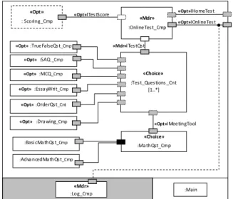
The reference architecture of the evaluation crosscutting-SPL is presented by Fig. 4. The evaluation component provides at least one obligatory interface which is test interface that allow handling online tests functionality. It may provide other optional interfaces for homework, report cards and certification functionalities. Fig. 5 shows the internal structure of the component 'test'. An OnlineTest_Cmp instance may include one or more questions of various kinds. The question components themselves may have various implementations according to the context as in the case of mathQst_Cmp. The model presents a set of questions components, more questions kinds can be introduced, as we can go in more detail for
each question type. For example, drawing tools may provide curves and tables tools for mathematic applications, modeling tools for computer science applications, and graphs for statistics applications and so on.
The partial derivation of the evaluation crosscutting-SPL architecture to be reused by the e-Primary crosscutting-SPL results in the same reference architecture as in Fig. 4. However, the internal structure of components is altered. For instance, the partial derivation of the test component for e-Primary SPL results in the model reported in Fig. 6.
:Main
«Mdr»
:Log_Cmp
«Mdr»
:OnlineTes t_Cmp «Opt»IOnlineTes t
«Opt»
: Scoring_Cmp
«Choice»
:Tes t_Ques tions _Cnt [1..*]
«Choice»
:Ma thQst_Cmp «Opt»ITes tScore
«Mdr»ITes tQs t :Basi cMa thQs t_Cmp :Adva ncedMa thQs t_Cmp «Opt»IMeetingTool s «Opt»IHomeTes t «Opt» :TrueFalseQs t_Cmp «Opt» :OrderQs t_Cnt
«Opt» :Dra wing_Cmp
«Opt» :SAQ _Cmp
«Opt» :MCQ_Cmp
«Opt» :Essa yWri t_Cmp
Fig.5. The internal structure of the component 'test'.
:Main
«Mdr»
:Log_Cmp
«Mdr»
:OnlineTes t_Cmp «Opt»IOnlineTes t
«Opt»
: Scoring_Cmp
«Choice»
:Tes t_Ques tions _Cnt [1..*]
«Opt»ITes tScore
«Mdr»ITestQst
«Mdr» :BasicMa thQst_Cmp
«Opt»IHomeTes t
«Opt» :TrueFalseQs t_Cmp
«Mdr» :OrderQs t_Cnt
«Opt» :Dra wing_Cmp
«Mdr» :SAQ _Cmp
«Opt» :MCQ_Cmp
Fig.6. Partially derived test component.
E-Primary applications usually need some basic questions such as: Short Answer Questions (SAQ) and Order questions, therefore the corresponding components takes mandatory type instead of optional. Only basic mathematic questions are required then the MathQst_cmp component is replaced by BasicMathQst_cmp component. Furthermore, new components can be added to the application such as: match the items, fill with the correct word, conjugation questions and others. Differently, if we derive partially the evaluation SPL to be reused in e-Coaching SPL the HomeWork_Cmp is omitted. In the case of partially deriving the evaluation SPL for an e-Math SPL which produces specialized applications in providing mathematic courses, the resulted partially
derived SPL do not need essayWrite_cmp and order_cmp components, yet it requires choosing AdvancedMathQst_cmp implementation for MathQst_cmp.
The composition model of e-University SPL with its crosscutting SPLs corresponds to its reference architecture as shown by the Fig. 7. All of DownloadOfficialDocs, AddModule, DataValidation and Communication components are annotated by CC_cmp and will be replaced by the relative partially derived crosscutting SPLs respectively Official Documents, Additional Module, Data Validation and Communication crosscutting SPLs. Official Documents SPL provides functionalities for documents authentication, download, archiving and so on. Additional modules encompasses SPLs producing components that do not represent the core of e-Learning applications but that can be added to those applications when needed, such as: research, poll, statistics SPLs. Data Validation SPL aims for developing validation components that will be integrated in e-learning applications to ensure the correctness and reliability of the provided information. Communication SPL should provide e-Learning institutions by communication components that fit their different needs such as: supporting several data formats, communication protocols, and basically to provide efficient security means. Those crosscutting SPLs are partially derived according to the reusing SPL requirements (in this case e-University SPL) and are composed with the other SPL components according to the reference architecture.
«Mdr» :UserManagement Cmp «Mdr»ICompteEvent : Main «Mdr» :Log_cmp «Opt»IUserDeclar ation «Mdr»IReques tDoc «Mdr» :RequestDoc_Cmp «Opt»IModifi ca tion «Opt» :DocModification Cmp «Opt» :DataValidation CC_cmp «Opt»IValidatio n «Mdr»IDocManage «Mdr» :DocManagement Cmp «Opt» :DeclarationEvent Cmp
«Opt»IDecla ra tion
«Opt»IAddModul e
«Mdr»IConfi gura tion
Even «Mdr» :Configuration_Cmp «Opt» :AddModule CC_cmp «Opt»IDownloadDoc «Opt» :DownloadOfficialDocs CC_cmp
«Opt»ICommuni ca tion
Even «Opt» :Communication CC_Cmp «Mdr»IUserConfi g «Opt»IDocDownload
Fig.7. The reference architecture of e-University SPL.
VI. RESULTS AND DISCUSSION
The validation case study shows a small part from the project on which we are working (section 2.C). The proposed approach brings several benefits to the project. On the one hand, the separation of concerns allows us to organize the e-Gov MPL, to differentiate between the
reusable SPLs (crosscutting SPLs) and the e-Gov MPL SPLs and to better structure the MPL model for simplifying the SPLs integration thereafter. The separation of concerns provides in fact a good method for systematizing reuse within an MPL by isolating the reusable components in specialized SPLs (crosscutting SPLs). On the other hand, the partial derivation helps us to avoid delaying the SPLs composition until getting the application level, where it is likely to have incompatible instances derived from separate SPLs. The early integration of partially derived SPLs avoids this problem, and the resulted composed SPLs will be derived as ordinary SPLs. In contrast to reusing instances, the SPLs partial derivation provides better means for reusing SPLs in a wider way. In the rest of this section, we discuss some crucial points related to our approach.
In conventional SPLs environments, the derivation of a final application implies usually a single user working on the derivation of a single variability model. Otherwise, MPLs environments include several sub-systems and multiple users are involved to derive the various variability models. Thus, multiple derivation processes are handled simultaneously for the various MPL sub-SPLs and this activity is known as distributed derivation. In such a case the communication is needed between the involved users in order to guarantee awareness about the decisions made in the deferent sub-SPLs [22]. If final applications should be integrated in order to produce a complete system, compatibility is needed among the components to be integrated, otherwise adaptation challenges will be encountered. Furthermore, competitive SPLs producing similar products may delay the derivation processes of an SPL reusing their outputs. If components needed by an SPL are provided by several other MPL SPLs, choosing the right component for reuse requires a whole decision process that results in lengthening the production operation. In our approach we act differently, instead of waiting until the derivation phase and facing up the afore-mentioned challenges we suggest the early integration of MPL SPLs. SPLs to be reused are partially derive according to the reusing SPL and are composed during the domain engineering of the reusing SPL. The matter is to move from distributed derivation to traditional derivation since at derivation time reused components belong already to the reusing SPL.
For composing the various SPLs artefacts (requirements models, architecture model, code, etc.) we assumed that our approach is applied in an homogeneous environment, such as the same modeling languages and implementation techniques are used. Having the same language will help widely in the well performance of the composition activity. Moreover, it allows reaching final results in shorter development time and avoids long procedure of adaptation, transformation into common language and communication between stakeholders. On the other side, in the case of heterogeneous SPLs environments adaptations must be performed to carry out the composition phase. This can be done by transforming all SPLs models into a unified language or choosing the
language that have been adopted by most of the SPLs. Some propositions have been suggested in this area (section 4.C); yet considerable research work is still needed in order to provide SPLs developers by standardized languages and technologies.
The key step of our contribution is the partial derivation. This activity allows the early and full integration of SPLs artefacts. A major task to perform would be the automation of the partial derivation step. The partial derivation automation relies on two concepts: transformation rules and traceability. Transformation rules correspond to the various partial derivation techniques defined beforehand (section 4.B). Those techniques can be formalized for each SPL artefact. Moreover, traceability must be kept among artefacts to automate the passage through the various abstraction levels. For instance, when features are mapped to the architecture the feature model partial derivation results in a configuration that can be used for automating the architecture model partial derivation. Nevertheless, this task cannot be fully automated since there are some partial derivation activities requiring the involvement of users. Those activities stand mainly in the expansion partial derivation techniques. When adding a new element to the architecture, developer must interfere to define the properties of the new element and its dependencies with respect to the architecture.
Our approach seems spending more time at the MPL domain engineering. That is true because planning for reuse; analyzing crosscutting common features and building the set of crosscutting SPLs requires more time than it is the case for traditional MPLs (direct development of MPL sub-SPLs). However, the aim of our approach is to avoid longer and hard decision and adaptation procedures during the application engineering phase. The matter is that the SPLs base (crosscutting SPLs and sub-SPLs) once built will allow the fast production of final applications, while in the conventional case time is wasted for each new application derivation.
Finally, we note that both of separation of concerns and partial derivation activities are autonomous from each other, i.e. each of them can be used independently. For instance, separation of concerns can be used in an MPL environment for structuring the MPL model. It can be also adapted for decomposing a single SPL into a set of sub-SPLs and thus moving from single SPL to MPL approach. On the other side, partial derivation can be adopted for the merging of two separated SPLs aiming inter-SPLs reuse even if they do not belong necessarily to the same MPL.
VII. CONCLUSION AND FUTURE WORK
In this paper we have presented an approach that helps managing reuse across SPLs, avoids distributed derivation challenges and eases the composition of SPLs within an MPL. The key idea is to plan for reuse from the very beginning avoiding thus several problems encountered during MPLs derivation. At first step, the MPL is organized into two SPLs kinds: sub-SPLs and
crosscutting SPLs that produce reusable components for the sub-SPLs. Then, the crosscutting SPLs are partially-derived according to the reusing SPLs requirements. Finally, the partially-derived SPLs are merged with the reusing SPLs. The aim is to systematize reuse across MPL SPLs, prevent late derivation challenges by composing SPLs at early development stages, and thus gain in terms of time, cost, and effort of development. The approach is validated in the context of a MPL for e-Learning applications, and a discussion is presented in lights of the approach evaluation.
The presented approach steps are in fact uncoupled techniques i.e. they may be used separately in other contexts. For instance, separation of concerns may be used to structure the MPLs models or to transform a single SPL into an MPL. On the other side, if developers prevent reusing an SPL (an SPLs set) by another SPL, and that this latter is under development, partial derivation technique can be used to ease the SPLs integration and to avoid the derivation challenges.
Our approach tackles some MPLs development issues; nevertheless more research work is still needed in this area. In the future we aim to: define the partial derivation techniques for the various SPL core assets, and to formulate the proposed activities in order to allow the automation of the partial derivation process. It would be also important to test our approach in other MPLs environments than e-Government to reach further improvements.
ACKNOWLEDGMENT
This work is done in the context of the project “Towards a Software Product Line for E-Government Applications” conducted at LIMPAF Laboratory at Bouira University (Bouira, Algeria), with grant number: LIMPAF/CNEPRU/C00L07UN100120140008.
REFERENCES
[1] L.M. Northrop and C.C. Clements, “A Framework for Software Product Line Practice,” SEI, Version 5.0, http://www.sei.cmu.edu/, 30-05-2017
[2] P. Klaus, G. Böckle, and F. van der Linden, Software
Product Line Engineering: Foundations, Principles, and Techniques, Springer, 2005.
[3] F. Van der Linden, K. Schmid, and E. Rommes, Software
Product Lines in Action, The Best Industrial Practice in Product Line Engineering, Springer, 2007.
[4] H. Gerald, P. Grünbacher, and R. Rabiser, “A systematic review and an expert survey on capabilities supporting multi product lines,” Information and Software Technology, vol. 54, no. 8, 2012, pp. 828-852.
DOI:10.1016/j.infsof.2012.02.002.
[5] J. Savolainen, M. Mannion, and J. Kuusela, “Developing platforms for multiple software product lines,” Proc.
Software Product Line Conf. (CBPL 12), 2012, pp.
220-228.
[6] J. Bosch, “The challenges of broadening the scope of software product families,” Communications of the ACM, vol. 49, no. 12, 2006, pp. 41-44.
[7] A. Guendouz, and D. Bennouar, “Component-Based Specification of Software Product Line Architecture,”
Proc. Int. Conference on Advanced Aspects of Software Engineering (ICAASE 14), 2014, pp. 100-107
[8] S. Kaliraj, N. Premkumar, A. Bharathi, "The Novel Life Cycle Model for Component Based Software System Based on Architecture Quality Using KCW Framework", International Journal of Information Technology and Computer Science(IJITCS), vol.6, no.9, pp.74-79, 2014. DOI: 10.5815/ijitcs.2014.09.10.
[9] M. Rizwan Jameel Qureshi, Ahmed Barnawi, "Evaluation of the Extended CBD Model: A Case Study using IMS Application", International Journal of Information Technology and Computer Science (IJITCS), vol.5, no.7, pp.36-42, 2013. DOI: 10.5815/ijitcs.2013.07.04.
[10] A. Colin, B. Joachim, and M. Dirk, “Component-Based Product Line Development: The KobrA Approach,” Proc.
Software Product Line Conf. (SPLC), 2000.
[11] O. Rob van, “The Koala component model for consumer electronics software,” Philips Research Eindhoven, IEEE
Computer, vol. 33, no. 3, 2000.
[12] A. Timo, S. Timo, and M. Tomi, “A Koala-Based Approach for Modelling and Deploying Configurable Software Product Families,” PFE-5, 2004.
[13] D. Bennouar, “The Integrated Approach to Software Architecture,” ” PhD dissertation, high school of Computer Science, Oued Smar, Algiers, 2009.
[14] D. Bennouar, and A. Saadi, “The Design of an eGovernment Application Using an Aspect Oriented Software Architecture Approach,” AOSA conf., 2009. [15] D. Bennouar, A. Henni, and A. Saadi, “The Design of A
Complex Software System Using A Software Architecture Approach,” The International Arab Conference on
Information Technology (ACIT 08), 2008.
[16] D. Bennouar, T. Khammaci, and A. Henni, “A new approach for component’s port modeling in software architecture,” Journal of System and Software Elsevier, vol. 83, no. 8, 2010. DOI:10.1016/j.jss.2010.03.005. [17] M. Rosenmüller, N. Siegmund, C. Kästner, and S. ur R.
Syed, Modeling dependent software product lines, Pro. of
the GPCE Workshop on Modularization, Composition and Generative Techniques for Product Line Engineering (McGPLE), 2008, pp. 13-18.
[18] M. Rosenmüller, and N. Siegmund, “Automating the Configuration of Multi Software Product Lines,” VaMoS
10, 2010, pp. 123-130.
[19] R. Schröter, “Using Multi-Level Interfaces to Improve Analyses of Multi Product Lines,” Technical report, Otto-von-Guericke University Magdeburg, Germany, 2014. [20] R. Schröter, N. Siegmund, and T. Thüm, “Towards
modular analysis of multi product lines,” Pro. of the 17th
Int. Software Product Line Conference co-located workshops, ACM, 2013, pp. 96-99.
[21] H. Hartmann, and T. Trew, “Using feature diagrams with context variability to model multiple product lines for software supply chains,” Pro. Software Product Line
Conference, IEEE, 2008, pp. 12-21.
[22] R. Rabiser, P. Grünbacher, and G. Holl, “Improving awareness during product derivation in multi-user multi product line environments,” Proc. of the 1st
Int. Workshop on Automated Configuration and Tailoring of Applications (ACoTA 10), in Conjunction with 25th IEEE/ACM
International Conference on Automated Software
Engineering (ASE’10), CEUR-WS, 2010, pp. 1–5. [23] D. Dhungana, P. Grünbacher, R. Rabiser, and T.
Neumayer, “Structuring the modeling space and supporting evolution in software product line engineering,” Journal of Systems and Software, vol. 83, no. 7, 2010, pp. 1108–1122.
[24] K. Czarnecki, S. Helsen and U. Eisenecker, “Staged configuration using feature models,” Proc. of Software
Product Lines Conference (SPLC’04), Springer Berlin Heidelberg, 2004 pp. 266-283.
[25] K. Czarnecki, S. Helsen and U. Eisenecker, “Staged configuration through specialization and multilevel configuration of feature models,” Software Process: Improvement and Practice, vol. 10, no. 2, 2005, pp.
143-169. DOI: 10.1002/spip.225.
[26] B. Morin, G. Vanwormhoudt, P. Lahire, A. Gaignard, O. Barais, and J. M. Jézéquel, “Managing variability complexity in aspect-oriented modeling,” Model Driven
Engineering Languages and Systems, Springer Berlin Heidelberg, 2008, pp. 797-812.
[27] B. Morin, J. Klein, O. Barais, and J. M. Jézéquel, “A generic weaver for supporting product lines,” Pro. of 13th
int. workshop on Early Aspects, ACM, 2008, pp. 11-18. [28] A. Abele, Y. Papadopoulos, D. Servat, M. Törngren, and
M. Weber, “The CVM Framework-A Prototype Tool for Compositional Variability Management,” VaMoS 10, 2010, pp. 101-105.
[29] M. Alférez, J. Santos, A. Moreira, A. Garcia, U. Kulesza, J. Araújo, and V. Amaral, “Multi-view composition language for software product line requirements,”
Software Language Engineering, Springer Berlin
Heidelberg, 2010, pp. 103-122.
[30] D. Dhungana, D. Seichter, G. Botterweck, R. Rabiser, P. Grunbacher, D. Benavides, and J. A. Galindo, “Configuration of multi product lines by bridging heterogeneous variability modeling approaches,” Software
Product Line Conference (SPLC) IEEE, 2011, pp.
120-129.
Authors’ Profiles
Amina Guendouz is a PhD candidate in
computer systems engineering at the Saad Dahlab University of Blida, Algeria, an Associate Researcher in the LIMPAF laboratory (Software System and Sensor Networks for Agriculture and Forestry) at the University of Bouira, Algeria, and a member of the LRDSI Lab at the Saad Dahlab University of Blida, Algeria. She obtained her BS (2009) and MSc (2011) degrees in Software Engineering from Blida University, Algeria. Her research interests include Software Architecture, Aspect Oriented Systems, E-Government, software reuse and Software Product Lines.
Djamal Bennouar is a Professor at the
University of Bouira, Algeria, an Associate Researcher in the National Center for the Development of Advanced Technologies (CDTA), Algiers, the Director of the LIMPAF laboratory (Software System and Sensor Networks for Agriculture and Forestry) and a member of the LRDSI Lab at the Saad Dahlab University of Blida, Algeria. He obtained the Magister degree from the National Institute for Computer Science (INI), Algeria, in 1993 and the PhD degree from the Ecole Superieure d’Informatique (ESI), Algeria, in 2009. His main research interests include Software
Architecture, Hardware Software Co-Design, Aspect Oriented Systems, E-Government and Software Product Lines. In the CDTA, D. Bennouar conducted various research related to VLSI CAD Frameworks (HDL, Inter tools communication, Engineering Databases), Computer Networking and Software Product Lines for E-Government. He is supervising a number of PhD students preparing their thesis in Software Architecture, Software Architecture Approach for System on Chip Design and Software Product Lines.
How to cite this paper: Amina Guendouz, Djamal Bennouar,
"Software Product Lines Composition through Partial Derivation", International Journal of Information Technology and Computer Science(IJITCS), Vol.9, No.10, pp.47-58, 2017. DOI: 10.5815/ijitcs.2017.10.05