3D Weak-Dispersion Reverse-Time Migration with a StereoModeling Method
Jingshuang Li*, Tsinghua University , Mike Fehler, Massachusetts Institute of Technology, Dinghui Yang, Xueyuan Huang, Tsinghua University
Summary
The finite difference method has been widely used in seismic modeling and reverse time migration. However, it generally has two issues: large computational cost and numerical dispersion. Recently, a nearly-analytic discrete operator was developed to approximate the partial differential operators. Based on this spatial discretization, many weak-dispersion and efficient StereoModeling methods have been developed, which are found to be superior to conventional algorithms in suppressing numerical dispersion. In this paper, we generalize one StereoModeling method, the nearly-analytic central difference method (NACD), from 2D to 3D and apply it to 3D reverse-time migration. Numerical results show that the NACD can be used effectively as a new tool for seismic modeling and migration. The reverse time migration (RTM) results for the 3D SEG/EAGE Phase A classic dataset 1 show that the NACD can get a much better image than the Lax-Wendroff correction (LWC) method particularly when using a coarse grid size.
Introduction
Subsurface geologic properties are very complex. To obtain the correct subsurface seismic images, we need two steps. One is to estimate accurate parameters, such as velocity, azimuth, and so on. The other step is to use migration algorithms that reliably express wave phenomena. Reverse time migration (Baysal et al, 1983; Whitmore, 1983) is drawing a lot of attention as the most powerful depth imaging method because of its ability to handle complex velocity models without dip limitations. The kernel of RTM is a method for modeling the two-way wavefield by solving the full wave equation. The finite difference (FD) method is a popular and easy way to implement RTM due to its efficiency and flexibility. A large number of FD schemes have been developed to solve acoustic and elastic wave equations (Alford et al., 1974; Kelly et al., 1976; Dablain, 1986; Takeuchi and Geller, 2000), and also applied to anisotropic and viscoelastic problems (Robertsson et al., 1994; Blanch and Robertsson, 1997; Zhang et al., 1999; Takeuchi and Geller, 2000). While high performance computing (HPC) has developed rapidly, RTM still has efficiency and memory problems and classical FD methods often suffer from serious numerical dispersion when models have strong velocity contrasts or too few samples per wavelength are used (Yang et al., 2006). Using high-order schemes or finer spatial grids are two ways to suppress the
numerical dispersion. Unfortunately, the suppression of numerical dispersion is a trade off with efficiency, because finer spatial grids bring shorter temporal step sizes, resulting in large storage space requirements and increased computational cost.
To effectively suppress the numerical dispersion caused by the discretization of the wave equation, a so called nearly-analytic discrete operator was introduced to approximate the partial differential operators (Yang et al., 2003; and Yang et
al., 2004; Yang et al., 2006). Combined with different time
schemes, several methods have been developed (Wang et al., 2009; Chen et al., 2010; Ma et al., 2010) based on this spatial scheme, and each has been found to be better than conventional algorithms at suppressing numerical dispersion. The approach was initially proposed by Konddoh (1991) and applied to solve parabolic equations (Konddoh et al., 1994). We call these new modeling methods StereoModeling methods.
Method
The StereoModeling Method borrows its name from an analogy to the StereoTomography (Billette and Lambaré, 1998) for ray-based seismic velocity. As is well known, travel time tomography uses only picked travel times in velocity inversion. StereoTomography uses not only picked travel times, but also picked slopes which include local coherence information. Joint inversion of travel times and slopes greatly increases the resolution of inverted model parameters. Analogously, conventional FD modeling uses only wave field in computing higher spatial derivatives. Correspondingly StereoModeling uses not only wave field, but also its gradient or first order spatial derivatives when constructing high order spatial derivatives. During the wave propagation, both wave field and its gradient are propagated simultaneously. Including wave gradient information greatly increases the representation accuracy of high order spatial derivatives, thus improving the wave simulation quality because of less numerical dispersion, less numerical anisotropy and increased efficiency. The main difference between the StereoModeling method and conventional FD is the evaluation of high order spatial derivatives. Taking the 1D case for example, the conventional representation of spatial derivatives can be given by the following formula (Fornberg, 1988):
( )
( )
) 1 ( , , , 1 , , 1 , 0 N m m M;n , m n j j x f m n,j α x m d x f m d x x ∑ = ⋅⋅⋅ = + ⋅ ⋅⋅ = ≈ =3D Weak-dispersion RTM method with StereoModeling
where M is the order of the highest derivatives to be approximated, 𝛼𝑛,𝑗𝑚 is the coefficient for the mth-order derivative of function f(x) at grid point j when n+1 points are used. Inspection of this formula leads us to conclude that conventional FD has an expanded computational stencil, which means the number of grid points is no less than the order of the derivative to be calculated. For example, for a 4th-order derivative, at least four grid points are needed and the higher order derivative computed, the more grid points are needed. What’s more, when used in a wave equation solver, only grid points along axis-directions may be used which makes a linear computational stencil structure. This results in the numerical anisotropy because the information about off-axis points is missing. Correspondingly, the representation of high order spatial derivatives for StereoModeling is formulated as bellow (Yang, 2003, 2004, 2006):
In this formulation, function values in addition to their first order derivative are used in the construction of higher order derivatives. Secondly the computational stencil is compact. To achieve fourth-order accuracy in space, only three grid points are used for all high-order derivatives. To achieve higher order accuracy, the grid points needed will increase, but will remain the same for all. Last when used in a wave equation solver, the computational stencil has an areal structure for 2D and cubic structure for 3D. These 9-point (3x3) or 27-point (3x3x3) stencils use off-axis points, which result in much less numerical anisotropy than a conventional linear stencil. What’s more, for StereoModeling the gradient information would be useful for angle gather computation in RTM, filtering, some new imaging conditions (Fleury et al., 2010) and some new acquisitions including wavefield gradients.
Here we apply the 3D case of NACD, one of the StereoModeling methods to 3D RTM. We briefly illustrate the theory of 3D NACD. With the StereoModeling definition 𝑈 = (𝑢, 𝜕𝑢 𝜕𝜕⁄ , 𝜕𝑢 𝜕𝜕⁄ , 𝜕𝑢 𝜕𝜕⁄ ) , and the acoustic wave equation, following the 2D case of NACD (Yang et al., 2012), we can obtain the following finite-difference scheme, which is both fourth-order accuracy in time and space:
Then the key of this scheme is how to solve the high order spatial derivatives, which also is the main difference with conventional FD method. Following the directional derivatives approach, which is introduced by Yang et al. in 2012, we could get the StereoModeling type expressions of all the spatial derivatives needed. This scheme has symmetric structure which guarantees a great stability and all the beneficial characteristics of StereoModeling methods that enable effective wave propagation modeling on a large-scale.
Numerical results
In order to demonstrate the numerical dispersion of the methods in the 3D case, we consider the following 3D scalar wave equation:
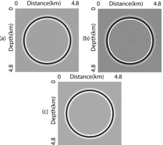
We first test a simple homogenous case, choosing the acoustic velocity to be 4 km/sec and the Courant number to be 0.2. The computational domain is 0 ≤ x ≤4.8 km, 0 ≤ y ≤ 4.8 km and 0 ≤ z ≤ 4.8 km. A 15 Hz center frequency Ricker wavelet explosive source is located at the center of the computational domain. Figure 1a and b show wavefield snapshots at t = 0.54 sec on the vertical plane containing the source when using a coarse computational grid (Δx = Δy = Δz= 40 m) generated by the NACD (a) and the fourth-order LWC (b), respectively. To compare their computational cost for producing a comparable quality of images, we compute the same wavefield by the LWC in finer spatial increments. Figure 1c shows the wavefield snapshot at t = 0.54 sec on a finer grid (Δx = Δy = Δz = 20 m), generated by the fourth-order LWC using the same Courant number. We can see that the wavefronts of seismic waves shown in Figure 1a and c, simulated by the NACD and the LWC respectively, are similar. Comparing Figure 1a and b, we can see that the NACD has no obvious numerical dispersion even though the space increment is 40 m. However, when the LWC and the NACD have the similar accuracy, their computational costs are quite different. It took the NACD about 140 sec to generate Figure 1a on a HPC cluster, whereas the LWC method took about 480 sec to generate Figure 1c under the same condition. For this simple simulation, the computational speed of the NACD is roughly 3.4 times faster than that of ) 2 ( . 5 , 4 , 3 , 2 , ) ( ) ( ) ( 3 1 = + ≈
∑
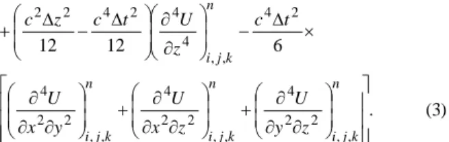
= = m dx x df x f dx x f d j j m j j m j x x m m β α n k j i n k j i n k j i n k j i n k j i n k j i n k j i n k j i n k j i n k j i n k j i n k j i n k j i n k j i y U t c y c x U t c x c z U U U y U U U x U U U t U U U , , 4 4 2 4 2 2 , , 4 4 2 4 2 2 2 1 , , , , 1 , , 2 , 1 , , , , 1 , 2 , , 1 , , , , 1 2 1 , , , , 1 , , 12 12 12 12 2 2 2 2 ∂ ∂ ∆ − ∆ + ∂ ∂ ∆ − ∆ + ∆ + − + ∆ + − + ∆ + − = ∆ + − − + − + − + − +( ) (
, ,)
. (4) 2 2 2 2 2 2 2 0 2 2 s s s y z x t f z u y u x u c t u = δ ∂ ∂ + ∂ ∂ + ∂ ∂ − ∂ ∂ ) 3 ( . 6 12 12 , , 2 2 4 , , 2 2 4 , , 2 2 4 2 4 , , 4 4 2 4 2 2 ∂ ∂ ∂ + ∂ ∂ ∂ + ∂ ∂ ∂ × ∆ − ∂ ∂ ∆ − ∆ + n k j i n k j i n k j i n k j i z y U z x U y x U t c z U t c z c3D Weak-dispersion RTM method with StereoModeling
the fourth order LWC. Furthermore, their memory requirements are different. The NACD needs nine arrays to store the wave displacement and gradients at each spatial grid point, and the number of grid points is 120×120×120 on the coarse grid (40m). The fourth-order LWC needs only three arrays to store the wave displacement at each grid point, but the number of grid points on the fine grid (20m) goes up to 240×240×240. It indicates that the NACD requires only roughly 1/8 of the storage space for the fourth-order LWC for comparable reliability.
Figure 1. Snapshots obtained with (a) NACD (Δx = Δy = Δz = 40 m), (b) fourth-order LWC (Δx = Δy = Δz = 40 m), (c) fourth-order LWC (Δx = Δy = Δz =20 m).
3D SEG/EAGE Phase A Classic Dataset 1
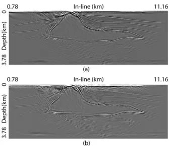
We present results of a test RTM using the NACD method with 3D SEG/EAGE Phase A classic dataset 1 and compare the results with the LWC method.In Phase A, two 138 shot 3D shot lines that are oriented perpendicular to each other with their intersection at the crest of the salt were acquired. The Phase A classic dataset 1 is extracted from the acquisition along line 1. For this dataset, each shot has a 6 streamer marine acquisition with a maximum of 65 groups per streamer. Group interval is 40 m, near offset is 160 m, far offset is 2720 m. Sample interval is 8 ms, recording time is 5 sec. The shot and receiver layout is shown in Figure 2. In this experiment, we choose a Ricker wavelet with a peak frequency of 18 Hz as the source wavelet. The grid sizes are 40 m and 20 m in the horizontal and vertical directions, respectively. The vertical plane of the velocity model, right below the source line, is shown in Figure 3. Figure 4a and b show the reverse time migration results of the Phase A classic dataset 1 computed using the NACD and the LWC, respectively. The two images in Figure 4 demonstrate that the NACD has better performance than the LWC method when
the same grid spacing is used, especially in the regions above the left and right salt flanks.In Figure 4a, the whole image is very clear and each interface above the salt is well imaged, but in the corresponding regions in Figure 4b, the interface closed to salt can hardly be distinguished. Moreover, the salt is correctly positioned in Figure 4a, but in Figure 4b the salt is a little shifted. In addition, comparison between Figure 4a and b indicates that most structure of the model can be well imaged by the NACD method even using a coarse grid size.
Figure 2. The Phase A Classic 1 acquisition over the SEG/EAGE salt model. In Figure 2a, the black stars indicate the zone containing the shot positions, and the black box indicates the position of the migrated volume. Figure 2b shows the layout of receivers for one shot. This dataset consists of one line with 138 shots. There are 6 streamers per shot, with a maximum of 65 receivers per streamer. The spacing of the shot positions is 80 m and the spacing of receivers is 40 m in the in-line and 80 m in cross-line direction.
Figure 3. A vertical plane of the SEG/EAGE velocity model taken right below the source line for Phase A classic dataset 1.
3D Weak-dispersion RTM method with StereoModeling
Figure 4. The reverse time migration results using (a) the NACD method and (b) the LWC method for the SEG/EAGE Phase A classic dataset 1.
Numerical dispersion
As shown in Figure 4, most differences of the images are focused in the shallow part and one of the reasons might be the smaller grid size in vertical direction. To better understand the reason why the NACD method behaves better than the LWC methods when using a coarse grid size and provides a better image under the same condition than does LWC, we do a simple numerical dispersion analysis. Numerical dispersion causes the phase velocity to vary with both the spatial and temporal frequencies. The computational merit of most numerical schemes always hinges on their ability to minimize this effect. Following the analysis presented by Moczo et al. in 2000, in this section, we investigate the numerical dispersion of the 3D NACD method and LWC method. A simple spectrum analysis shows that the spectrum of the data mainly ranges from about 9 Hz to 36 Hz as shown in Figure 5a. According to the migration above, we choose Courant number α=0.2 and spatial grid size to be 40 m. The dispersion relation, which is as a function of the sampling rate, is transformed into a function of frequency. Figure 5b and c show representative dispersion relation curves correspond to different propagation directions. These curves show that the maximum phase-velocity error of NACD is less than 8%, whereas the maximum error of the LWC is about as high as 28% over the frequency range of the data, which helps to explain the migration results.
Conclusions
We apply the 3D StereoModeling method to RTM, and get a weak-dispersion pre-stack depth migration method that
allows large extrapolation grid size to be used. Numerical results illustrate that the StereoModeling method, which uses both the wave displacement and its gradients, can greatly increase the computational efficiency and save computer memory through using the large spatial increments and the resulting large time steps. StereoModeling methods are also quite effective in suppressing the numerical dispersion both in modeling and imaging even when coarse grids are used, compared with conventional numerical methods such as fourth-order LWC. These results imply StereoModeling methods have a promising future in 3D imaging.
Acknowledgement
This work was supported by the ERL Founding Members Consortium. Jingshuang Li was supported by China Scholarship Council. We thank SEG/EAGE to make the 3D SEG/EAGE classic dataset 1 available.
Figure 5. (a) The spectrum of the dataset, of which the amplitude is normalized. The ratio R of the numerical wave velocity to the phase velocity versus the frequency for (b) the NACD method and (c) LWC method with Courant number
α=0.2, in which φ is the wave propagating angle to the
z-axis, and θ is the propagating angle of the wave projection in the xy plane to the x-axis.