3 GHz Yb-Fiber Laser Based
Femtosecond Sources and Frequency Comb
by
Hung-Wen Chen
B.S., Physics, National Taiwan University, 2004
M.S., Electro-Optical Engineering, National Taiwan University, 2006 Submitted to the Department of Electrical Engineering and Computer Science
in partial fulfillment of the requirements for the degree of
Doctor of Philosophy in Electrical Engineering and Computer Science
AiRCHNES
at the MASSACHUSETTSIINS J
OF TECHNOLOGY
MASSACHUSETTS INSTITUTE OF TECHNOLOGY
JUN 3
0
2014
June 2014 f
© 2014 Massachusetts Institute of Technology. All rights reserved. .-
LIBRARES
Author
...
S ignature redacted
Hung-Wen Chen
Department of Electrical Engineering and Computer Science
April 29th, 2014
Certified by...Signature
redacted
Franz X. KArtner
Professor of Electrical Engineering Thesis Supervisor
Signature redacted
Certified by... . ... Erich P. Ippen
Elihu Thomson Professor of Electrical Engineering, Professor of Physics Thesis Supervisor
Accepted by...
Signature redacted
eslie A. Kolodziejski
ProfessoYo aectrical Engineering Chair, Department Committee on Graduate Theses
3 GHz Yb-Fiber Laser Based
Femtosecond Sources and Frequency Comb
by
Hung-Wen Chen
Submitted to the Department of Electrical Engineering and Computer Science on April 29th, 2014,
in partial fulfillment of the requirements for the degree of Doctor of Philosophy in Electrical Engineering and Computer Science
Abstract
Many applications require femtosecond lasers of high repetition rate. In the time domain, a higher repetition rate means more pulses in a fixed time period. For nonlinear bio-optical imaging in which photoinduced damage is caused by pulse energy rather than average power, increasing pulse repetition-rate will improve signal-to-noise ratio and reduce data acquisition time. In the frequency domain, a higher repetition rate means the comb line spacing is larger. This permits access to and manipulation of each individual comb line. Such capabilities have opened numerous frequency-domain applications including optical arbitrary waveform generation, high-speed photonic analog-to-digital conversion, and high-resolution spectroscopy.
Femtosecond optical sources in the wavelength range between 0.7 jim and 1.55 pm have found many applications such as optical coherence tomography, high speed optical sampling, photonic analog-to-digital conversion, and multi-photon spectroscopy. To date, femtosecond solid-state lasers are mainly employed in these applications. Take two most common femtosecond solid-state lasers for example: a Ti:sapphire laser can cover 0.7-1.1 jIm and is useful for optical coherence tomography and multi-photon biological imaging. A Cr:forsterite laser can operate in the wavelength range 1.15-1.35 jim, an important wavelength range for multi-photon microscopy because light in this wavelength range experiences lower scattering loss and higher penetration depth for most biology samples. Nonetheless, solid-state lasers are usually expensive, bulky, and prone to misalignment. The gain crystals often requires water cooling. These disadvantages hamper their wide usage outside the lab environment. The mentioned versatile applications can be even more widespread used if we are able to make the femtosecond laser sources less expensive, flexible, and easy to maintain.
In this dissertation, 3-GHz femtosecond laser sources are demonstrated. These sources are useful for applications in optical coherence tomography, optical frequency metrology, multi-photon biological imaging, photonic analog-to-digital conversion, etc. First, a 3-GHz fundamentally mode-locked Yb-fiber laser is demonstrated with the highest rep-rate among all femtosecond Yb-fiber lasers to date. We then numerically and experimentally study the optimization of femtosecond YDFAs in order to achieve both high-quality and high-power compressed pulses in the
3 GHz high power fiber laser system. Using the 3 GHz high power femtosecond Yb-fiber laser system,
a few-cycle ultrafast source at the Ti:sapphire laser wavelength is demonstrated as a promising substitute of multi-GHz mode-locked Ti:sapphire lasers. In addition, a watt-level, femtosecond
Raman soliton source wavelength-tunable from 1.15 prm to 1.35 [rm is implemented. Such a Raman soliton source exhibits both the highest repetition rate and highest average power to the best of our knowledge. Finally, preliminary work on a 3 GHz passive frequency comb via difference frequency generation at 1.5 [m is demonstrated. This is currently the highest rep-rate frequency comb in the telecommunication wavelength range.
Thesis Supervisor: Franz X. Kartner Title: Professor of Electrical Engineering
Thesis Supervisor: Erich P. Ippen
Acknowledgements
First of all, I would like to express my profound gratitude to my advisor Prof. Franz Kartner for offering me the golden opportunity to be in OQE group. During my PhD career, he gave me a lot of freedom in research and was open-minded to my ideas and opinions. Whenever I faced challenges of any kind, he always provided invaluable suggestions. His exemplary guidance and encouragement constantly supported me so that I could accomplish many which I once thought impossible. I believe that his words will carry me a long way in my journey of life.
Also, I would like to thank Prof. Erich Ippen and Prof. Fujimoto for their precious time and all the advice, especially Prof. Fujimoto from whom I learned a lot as the 6.634 teaching assistant in my last semester. On his own feet, he showed me the importance of making contribution to the society and his respectable attitude toward education. While working with him, I had seen him spending enormous amount of time on the students and the course, which I truly admire.
I received so much help from many people, particularly those in OQE group. Every OQE member was
always friendly and helpful when I encountered problems either in my research or daily life. I sincerely appreciate their assistance. Largely I would like to thank Dr. Guoqing Noah Chang who led
me into the field of fiber laser technology. He played a very important role in my PhD life. He was not only a mentor to me but also a best friend of mine. His office door was always open for me. I could drop by his office and interrupt at any time when I had anything that I wanted to discuss with him. He was always willing to spare his time for me and to generously share his experiences and knowledge in any aspects. His mentoring and friendship made my PhD life pleasant and stress-free. The enjoyable moments we created together in his office will permanently exist in my heart. Moreover, I would like to thank for Jinkang Lim's help while we worked on the 3 GHz Yb-fiber laser system, and Duo Li's help while we worked closely on my last project, EPHI. Special thanks to the astro-comb team at Harvard University for letting me participate in one of the coolest projects in the world.
I also want to thank all the members in Republic of China (Taiwan) student association, mainly those
in OQE group (Li-Jin Chen, Tsung-Han Tsai, Shu-Wei Huang, Chien-Jen Lai, Hsiang-Chieh Lee, and Jonathan Liu). Life in Boston was even more colorful with their company. Deeply I would like to convey my thankfulness to Li-Jin Chen who has helped me tremendously since the first day I got to know him. Many thanks to Prof. Chi-Kuang Sun, my former advisor at National Taiwan University, for the training and support before I came to the US.
Last but not least, I would like to greatly thank my dear family-my parents, Fu-Tien Chen and Nien-Yun Lin, my siblings, Yu-Chen Chen and Chiu-Ling Chen, and my wife, Ya-Hui Chang. Without their substantial backing up, I would not have gotten as far as I have. Mostly I'd like to thank my dearest wife, my soul mate, Ya-Hui. No matter what difficulties I face, she is always by my side. When
I got the MIT admission, she was willing to give up her high salary and life in Taiwan and came to the US with me. I would say at least half of my PhD degree should belong to her. My appreciation toward
my family is way beyond words. For that reason, I would like to dedicate this thesis to them and also to our incoming baby girl, Evelyn Chen.
Publication List
Referred Journal Publications
[1] J. Lim, H.-W. Chen, S. Xu, Z. Yang, F. X. Kartner, and G. Chang, "3 GHz, Watt-level femtosecond Raman soliton source," Opt. Lett. 39, 2060-2063, 2014.
[2] H.-W. Chen, H. Zia, J. Lim, S. Xu, Z. Yang, F. X. Kartner, and G. Chang, "3 GHz, Yb-fiber laser based, few-cycle ultrafast source at the Ti:sapphire laser wavelength," Opt. Lett. 38, 4927-4930, 2013. (Top of Downloads in November 2013)
[3] J. Lim, H.-W. Chen, G. Chang, and F. X. Kartner, "Frequency comb based on a narrowband
Yb-fiber oscillator: pre-chirp management for self-referenced carrier envelope offset frequency stabilization," Opt. Express 21, 4531-4538, 2013.
[4] H.-W. Chen, J. Lim, S.-W. Huang, D. N. Schimpf, F. X. K5rtner, and G. Chang, "Optimization of femtosecond Yb-doped fiber amplifiers for high-quality pulse compression," Opt. Express 20, 28672-28682, 2012.
[5] H.-W. Chen, G. Chang, S. Xu, Z. Yang, and F. X. Kartner, "3 GHz, fundamentally mode-locked, femtosecond Yb-fiber laser," Opt. Lett. 37, 3522-3524, 2012.
[6] H.-W. Chen, T. Sosnowski, C.-H. Liu, L.-J. Chen, J. Birge, A. Galvanauskas, F. X. Kartner, and G. Q. Chang, "Chirally-coupled-core Yb-fiber laser delivering 80-fs pulses with diffraction-limited beam quality warranted by a high-dispersion-mirror based compressor," Opt. Express 18,
24699, 2010.
[7] C.-M. Chiu, H.-W. Chen, Y.-R. Huang, Y.-J. Hwang, W.-J. Lee, H.-Y. Huang, and C.-K. Sun, "All-THz fiber-scanning near-field microscopy," Opt. Lett. 34, pp. 1084-1086, 2009.
[8] H.-W. Chen, C.-M. Chiu, J.-L. Kuo, P.-J. Chiang, H.-C. Chang, and C.-K. Sun, "Subwavelength dielectric-fiber-based terahertz coupler," J. Light. Technol. 27, 1489-1495, 2009.
[9] C.-H. Lai, Y.-C. Hsueh, H.-W. Chen, Y.-J. Huang, H.-C. Chang and C.-K. Sun, "Low-Index Terahertz
Pipe Waveguides," Opt. Lett. 34, 3457-3459, 2009.
[10] J.-Y. Lu, C.-C. Kuo, C.-M. Chiu, H.-W. Chen, Y.-J. Hwang, C.-L. Pan, and C.-K. Sun, "THz interferomertric imaging using subwavelength plastic fiber based THz endoscope," Opt.
Express 16, 2494-2501, 2008.
[11] J.-Y. Lu, C.-P. Yu, H.-C. Chang, H.-W. Chen, Y.-T. Li, C.-L. Pan, and C.-K. Sun, "THz Air-core Microstructure Fiber," Appl. Phys. Lett. 92, 064105, 2008.
[12] H.-W. Chen, Y.-T. Li, J.-L. Kuo, J.-Y. Lu, L.-J. Chen, C.-L. Pan, and C.-K. Sun, "Investigation on Spectral Loss Characteristics of Subwavelength Terahertz Fibers," Optics Lett. 32, 1017-1019, 2007.
[13] L.-J. Chen, H.-W. Chen, T.-F. Kao, J.-Y. Lu, and C.-K. Sun, "Low-loss Subwavelength Plastic Fiber
for Terahertz Wave Guiding," Opt. Lett. 31, 308-310, 2006.
[14] Y. Lu, L.-J. Chen, T.-F. Kao, H.-H. Chang, H.-W. Chen, A.-S. Liu, Y.-C. Chen, R.-B. Wu, W.-S. Liu, J.-1. Chyi, and C.-K. Sun, "Terahertz microchip for illicit drug detection," IEEE Photon. Technol. Lett. 18, 2254-2256, 2006.
Referred Conference Proceedings
[1] H.-W. Chen, J. Lim, S. Xu, Z. Yang, F. X. Kartner, Guoqing Chang, "3-GHz, ultrafast Yb-fiber laser sources: filling spectral gap," SPIE Optical Engineering and Applications, manuscript in preparation. (Invited)
[2] H.-W. Chen, H. Zia, J. Lim, S. Xu, Z. Yang, and F. X. Kartner, "3 GHz few-cycle ultrafast source at
850nm," in Frontiers in Optics 2013/Laser Science XXIX, OSA Technical Digest (CD) (Optical Society of America, 2013), FW6B.2. (Postdeadline)
[3] H.-W. Chen, J. Lim, S. Xu, Z. Yang, and F. X. Kartner, "Yb-Fiber Oscillator Based, Few-Cycle Ultrafast Source At 850nm," in the 10th Conference on Lasers and Electro-Optics Pacific Rim and the 18th OptoElectronics and Communications Conference/Photonics in Switching 2013
(CLEO-PR & OECC/PS2013), CM2I.4. (Best Paper Award).
[4] H.-W. Chen, G. Chang, C. Zhu, X. Ma, A. Galvanauskas, and F. X. Kartner, "Air-clad chirally-coupled-core Yb-fiber femtosecond oscillator with >10W average power," EPJ Web Conf. 41, 10006 (2013).
[5] H.-W. Chen, G. Chang, S.-W. Huang, D. N. Schimpf, and F. X. Kartner, "High-quality pulse-compression of pre-chirped pulses in fiber-amplifiers," in 2012 Conference on Lasers and Electro-Optics (CLEO) (2012), CM4N.3.
[6] H.-W. Chen, T. Sosnowski, C.-H. Liu, L.-J Chen, J. R. Birge, A. Galvanauskas, F. X. Kartner, and G. Q. Chang, "High-energy chirally-coupled-core Yb-fiber laser with high dispersion mirror compressor to achieve 1W-level, sub-100fs pulses with diffraction-limited beam quality," paper ATuC5, Advanced Solid-State Photonics (ASSP), Istanbul, Turkey, 2011.
[7] H.-W. Chen, C.-M. Chiu, Y.-R. Huang, C.-C. Kuo, Y.-J. Huang, W.-J. Lee, C.-K. Sun, "THz
Subwavelength-Fiber-based Near-Field Microscope," CLEO/IQEC, paper CWM2, Baltimore, MD, U.S.A, 2009.
[8] H.-W. Chen, C.-M. Chiu, Y.-R. Huang, C.-C. Kuo, Y.-J. Huang, and C.-K. Sun, "Identifying Breast
Cancer Section using a Fiber-Scanning Near-Field THz Microscope," in Conference Proceedings of International Conference on Optics and Photonics in Taiwan (OPT'08), paper Fri-P1-198,
Taipei, Taiwan, 2008.
[9] H.-W. Chen, J.-Y. Lu, L.-J. Chen, P.-J. Chiang, H.-C. Chang, Y.-T. Li, C.-L. Pan, and C.-K. Sun, "THz Fiber Directional Coupler," Conference on Lasers and Electro-Optics/Quantum Electronics and Laser Science Conference/Conference on Photonic Applications, paper CThLL7, Baltimore, MD, USA, 2007.
[10] H.-W. Chen, J.-Y. Lu, L.-J. Chen, Y.-T. Li, C.-L. Pan, and C.-K. Sun, "Spectral Loss Characteristics of
Subwavelength THz Fibers," Conference on Lasers and Electro-Optics/Quantum Electronics and Laser Science Conference/Conference on Photonic Applications, paper CJWA107,
Baltimore, MD, US, 2007.
[11] H.-W. Chen, J.-Y. Lu, J.-L. Kuo, Y.-T. Li, C.-L. Pan, L.-J. Chen, and C.-K. Sun, "Study on attenuation
spectrum of subwavelength-diameter THz fiber," The 1st Asian-Pacific Workshop on THz Photonics, pp. 27-28, Hsinchu, Taiwan, 2006.
[12] H.-W. Chen, J.-Y. Lu, J.-L. Kuo, Y.-T. Li, C.-L. Pan, L.-J. Chen, P.-J. Chiang, H.-C. Chang, and C.-K. Sun, "THz fiber-based coupler," The 1st Asian-Pacific Workshop on THz Photonics, pp. 23-24, Hsinchu, Taiwan, 2006.
[13] D. Li, M. Peng, H.-W. Chen, J. Lim, M. Watts, and F. X. Kartner, "Fiber-Optic Demonstration of Optical Frequency Division for Erbium Silicon Photonics Integrated Oscillator," in 2014 Conference on Lasers and Electro-Optics (CLEO) (2014), SF11.3.
[14] G. Zhou, L. Wei, J. Lim, H.-W. Chen, F. X. Kartner, and G. Chang, "Relative intensity noise of Raman solitons" submitted to 6th EPS-QEOD EUROPHOTON CONFERENCE 2014.
[15] L. Wei, G. Zhou, J. Lim, H.-W. Chen, F. X. Kartner, and G. Chang, "Relative intensity noise of Raman solitons: which one is more noisy? " in 2014 Conference on Lasers and Electro-Optics
(CLEO) (2014), SM4N.7.
[16] N. Langellier, C.-H. Li, A. Glenday, G. Furesz, G. Chang, H.-W. Chen, J. Lim, A. Szentgyorgyi, D. Sasselov, D. Phillips, F. X. Kartner, and R. L. Walsworth "Broadband astrocomb at the HARPS-N spectrograph for Earth-like exoplanet searches," SPIE Astronomical Telescopes and Instrumentation Proceedings SPIE, 9147-326, 2014.
[17] G. Chang, H.-W. Chen, J. Lim, S. Xu, Z. Yang, and F. X. Kartner, "3 GHz, femtosecond Raman soliton source," in 2013 Conference on Lasers and Electro-Optics (CLEO) (2013), CM21.4.
[18] J. Lim, H.-W. Chen, G. Change, and F. X. Kartner, "Stable frequency comb derived from a narrowband Yb-fiber laser: pre-chirp management for self-referenced fCEO stabilization," in
2013 Conference on Lasers and Electro-Optics (CLEO) (2013), CM2I.7.
[19] J. Lim, H.-W. Chen, A.-L. Calendron, G. Chang, and F. X. Kartner, "Optimization of ultrafast Yb-doped fiber amplifiers to achieve high-quality compressed pulses," EPJ Web Conf. 41, 10020 (2013).
[20] A. Glenday, C.-H. Li, N. Langellier, G. Furesz, G. Chang, H.-W. Chen, J. Lim, F. Kartner, D. Phillips,
A. Szentgyorgyi, and R. Walsworth, "A high accuracy FTS for laser frequency combs, lamps and
other sources," in Bulletin of the American Physical Society (American Physical Society, 2013), Volume 58, Number 6.
[21] N. Langellier, A. Glenday, C.-H. Li, G. Furesz, G. Chang, H.-W. Chen, J. Lim, F. Kartner, D. Phillips, A. Szentgyorgyi, and R. Walsworth, "Green Astro-comb for exoplanet searches," in Bulletin of
the American Physical Society (American Physical Society, 2013), Volume 58, Number 6.
[22] D. Phillips, C.-H. Li, A. Glenday, N. Langellier, G. Furesz, G. Chang, H.-W. Chen, J. Lim, F. Kartner,
A. Szentgyorgyi, and R. Walsworth, "Green Astro-comb for exoplanet searches at HARPS-N," in
Bulletin of the American Physical Society (American Physical Society, 2013), Volume 58, Number 6.
[23] G. Chang, C.-H. Li, A. Glenday, G. Furesz, N. Langellier, L.-J. Chen, M. W. Webber, J. Lim, H.-W.
Chen, D. F. Phillips, A. Szentgyorgyi, R. L. Walsworth, and F. X. Kartner, "Spectrally flat,
broadband visible-wavelength astro-comb," in 2012 Conference on Lasers and Electro-Optics (CLEO) (2012), CF2C.4.
[24] Y. Zhou, G. Chang, H.-W. Chen, P. C. Chui, K. K.-Y. Wong, and F. X. Kartner, "Nonlinear-polarization-evolution mode-locking in a hybrid cavity: A route toward low repetition-rate fiber lasers," in 2012 Conference on Lasers and Electro-Optics (CLEO) (2012), CF3L.3.
[25] G. Chang, H.-W. Chen, S. Xu, Z. Yang, and F. X. Kartner, "2.46-GHz, fundamentally mode-locked, femtosecond Yb-fiber oscillator," in 5th EPS-QEOD EUROPHOTON CONFERENCE 2012, WeC.3.
[26] C.-H. Li, A. Glenday, N. Langellier, G. Furesz, M. Webber, G. Chang, L.-J. Chen, H.-W. Chen, J. Lim, F. K5rtner, D. Phillips, A. Szentgyorgyi, and R. Walsworth, "Green astro-comb for exoplanet searches," in Bulletin of the American Physical Society (American Physical Society, 2012), Volume 57, Number 5.
[27] D. Phillips, A. Glenday, C.-H. Li, G. Furesz, N. Langellier, M. Webber, G. Chang, L.-J. Chen, H.-W. Chen, J. Lim, F. Kartner, A. Szentgyorgyi, and R. Walsworth, "Generation of a green astro-comb using tapered photonic crystal fibers," in Bulletin of the American Physical Society (American
Physical Society, 2012), Volume 57, Number 5.
[28] A. Glenday, C.-H. Li, M. Webber, N. Langellier, G. Furesz, G. Chang, L.-J. Chen, H.-W. Chen, J. Lim, F. Kartner, D. Phillips, A. Szentgyorgyi, and R. Walsworth, "Characterization of a green astro-comb using a Fourier Transform Spectrometer," in Bulletin of the American Physical Society (American Physical Society, 2012), Volume 57, Number 5.
[29] A. Szentgyorgyi, A. J. Benedick, G. Q. Chang, H.-W. Chen, L.-J. Chen, G. Furesz, A. Glenday, F. X. Kartner, S. Korzennik, C.-H. Li, D. Phillips, R. L. Walsworth "Progress Toward Laser Calibration of Ultra-Precise Radial Velocity Measurements," Conf. on Astronomy of Exoplanets with Precise Radial Velocities, Penn State University, University Park, PA, USA, 2010.
[30] G. Chang, H.-W. Chen, T. Sosnowski, C.-H. Liu, L.- J. Chen, J. Birge, A. Galvanauskas, and F. Kartner, "High-energy Chirally-coupled-core Yb-fiber Oscillator with High-dispersion-mirror Compressor: Generation Of -1w, 80-fs Pulses With Diffraction-limited Beam Quality," in Frontiers in Optics 2010/Laser Science XXVI, OSA Technical Digest (CD) (Optical Society of America, 2010), PDPC3.
[31] A. J. Benedick, G. Q. Chang, H.-W. Chen, L.-J. Chen, G. Furesz, A. Glenday, F. X. Kurtner, S. Korzennik, C.-H. Li, A. Szentgyorgyi, D. Phillips, R. Walsworth, "Astro-comb calibration of the TRES spectrograph at visible wavelengths," Conf. on Astronomy of Exoplanets with Precise Radial Velocities, Penn State University, University Park, PA, USA, 2010.
[32] H. Chen, C.-C. Kuo, C.-Y. Chen, Y.-W. Hwang, H.-W. Chen, Y.-J. Hwang, and C.-K. Sun, "Attenuation
Measurement of Breast Cancer in Nude Mice in Terahertz Frequency Range," 6th Asian Conference on Ultrafast Phenomena, paper P60, pp. 166-167, Taipei, Taiwan, 2010.
[33] Y.-C. Hsueh, C.-H. Lai, H.-W. Chen, Y-J Huang, C.-C. Chang, and C.-K. Sun, "THz Anti-Resonant
Reflecting Tube Waveguide," CLEO/IQEC, paper CThQ5, Baltimore, MD, U.S.A, 2009.
[34] H. Chen, C.-C. Kuo, C.-Y. Chen, Y.-W. Hwang, H.-W. Chen, Y.-J. Hwang, and C.-K. Sun, "Attenuation
measurement of breast cancer in nude mice in the terahertz frequency range," Proceeding of Optics and Photonics in Taiwan, paper FP022, Taipei, Taiwan, 2009.
[35] J.-Y. Lu, C.-C. Kuo, C.-M. Chiu, H.-W. Chen, C.-L. Pan, and C.-K. Sun, "THz interferometric imaging using subwavelength plastic fiber based THz endoscopes," Conference on Lasers and Electro-Optics/Quantum Electronics and Laser Science Conference/Conference on Photonic
Applications, paper CThN5, San Jose, CA, USA, May 2008.
[36] C.-C. Kuo, C.-Y. Chen, Y.-W. Hwang, H.-W. Chen, Y.-J. Hwang, F.-H. Chang, and C.-K. Sun, "In-vivo measurement of THz absorption constants of the skin and xenografted colon cancer on nude
mice," in Conference Proceedings of International Conference on Optics and Photonics in Taiwan (OPT'08), paper Fri-P1-210, Taipei, Taiwan, 2008.
[37] J.-Y. Lu, H.-W. Chen, L.-J. Chen, and C.-K. Sun, "Sub-Wavelength THz Plastic Fibers," Photonics West, paper 6472-7, San Jose, CA, USA, 2007.
[38] J.-Y. Lu, C.-P. Yu, H.-C. Chang, H.-W. Chen, Y.-T. Li, C.-L. Pan, and C.-K. Sun, "Air-core microstructure fiber for terahertz radiation waveguiding," Conference on Lasers and Electro-Optics/Quantum Electronics and Laser Science Conference/Conference on Photonic Applications, paper CThLL5, Baltimore, MD, USA, 2007.
[39] C.-K. Sun, L.-J. Chen, H.-W. Chen, and J.-Y. Lu, "Subwavelength plastic fiber for terahertz wave
guiding," Optics East/ Conference on Terahertz Physics, Devices, and Systems, paper 6373-12, Boston, MA, Oct. 2006.
[40] L.-J. Chen, H.-W. Chen, T.-F. Kao, J.-Y. Lu, and C.-K. Sun, "Low-loss subwavelength THz plastic fibers," Conference on Lasers and Electro-Optics/Quantum Electronics and Laser Science Conference/Conference on Photonic Applications, paper CMS1, Long Beach, CA, USA, 2006.
[41] C.-K. Sun, Y. Lu, L.-J. Chen, T.-F. Kao, H.-W. Chen, A.-S. Liu, Y.-C. Yu, R.-B. Wu, W.-S. Liu, and
J.-I. Chyi, "THz microchip for instant illicit drug identification," The 1st Asian-Pacific Workshop
on THz Photonics, pp. 17-18, Hsinchu, Taiwan, 2006.
[42] J.-Y. Lu, Y.-T. Li, C.-L. Pan, C.-P. Yu, H.-C. Chang, H.-W. Chen, and C.-K. Sun, "Air-core microstructure fiber for terahertz radiation waveguiding," The 1st Asian-Pacific Workshop on THz Photonics, pp. 25-26, Hsinchu, Taiwan, 2006.
Patents
[1] C.-K. Sun, L.-J. Chen, and H.-W. Chen, "Plastic waveguide for terahertz wave," USA patent US7,409,132 B2, Aug. 2008.
[2] Y.-H. Chang and H.-W. Chen, "Necktie and Stickpin," Taiwan Patent D134917, May 21, 2010.
[3] Y.-C. Chen and H.-W. Chen, "Direction Pointer," Taiwan Patent M318168, Sep 1, 2007.
Other Publications
[1] H.-W. Chen, and C.-K. Sun, "Terahertz technology- fiber scanning imaging system," Physics
Bimonthly, vol. 31, 2009. (Invited Paper)
[2] H.-W. Chen, J.-Y. Lu, P.-J. Chiang, L.-J. Chen, H.-C. Chang, Y.-T. Li, C.-L. Pan, J.-L. Kuo, C.-K. Sun,
"Loss spectrum of sub-wavelength THz fiber and its application," Journal of Optical
Contents
Publication List ... 7
Chapter 1 Introduction...17
1.1 . B ack g ro u n d ... 17
1.2. Overview of the Thesis ... 20
Chapter 2 3-GHz M odelocked Yb-Fiber Oscillator...23
2.1. Background of High Repetition Rate Lasers ... 23
2.2. Key Components in Building a High Rep-rate Oscillator... 25
2.2.1 Heavily Yb-doped Phosphate Glass Fiber... 26
2.2.2 High-Dispersion Output Coupler ... 27
2.3. Experimental Setup...29
2.4. Laser Characterization ... 30
2 .5 . S u m m ary ... 3 3 Chapter 3 Optimization of Femtosecond Nonlinear Yb-Fiber Amplifiers based on a Narrowband Oscillator...35
3 .1. M o tiv atio n ... 3 5 3.2. M odeling Nonlinear Amplification of Femtosecond Pulses in YDFAs ... 36
3.3. Optimization of Different Amplifier Parameters ... 41
3.3.1 Optimization of the Input Pulse Pre-Chirp ... 41
3.3.2 Optimization of the Input Power and Optical Bandwidth ... 44
3.3.3 Optimization of the Yb-ion Doping Concentration ... 45
3 .4 . S u m m ary ... 4 7 Chapter 4 Frequency Comb based on a 280-MHz Narrowband Yb-fiber Oscillator...49
4 .1. M otiv atio n ... 4 9 4.2. Background of High Rep-rate Frequency Comb ... 49
4.3. Narrowband 280 M Hz Yb-Fiber Oscillator ... 52
4.4. Experimental Results on Pre-Chirp Management for Optimizing Compressed Pulse Quality ... 54
4.5. Frequency Comb based on the narrowband Yb-fiber oscillator ... 58
4.5.1 Pre-chirp M anagement for Spectral Broadening and Pulse Compression... 59
4.5.2 Supercontinuum Generation andfCEo Detection... 61
4.5.3 Stabilization offrep andfCEO ... 62
4 .6 . S u m m ary ... 64
5 .1. Intro d u ction ... 6 5
5.2. Experimental Setup ... 65
5.2.1 Pre-Chirp M anagement on High Power Yb-Fiber Amplifier ... 66
5.2.2 Optimized 3-GHz High Power Laser System ... 68
5.3. Noise Performance...69
5.3.1 Relative Intensity Noise ... 69
5.3.2 Timing Jitter andfiep Locking ... 70
5 .4 . S u m m ary ... 73
Chapter 6 Application I: 3 GHz Yb-fiber Laser Based Few-Cycle Source at the Ti:sapphire W avelength...75
6 .1. M otiv ation ... 7 5 6.2. Frequency Up-Conversion using Fiber-Optic Cherenkov Radiation... 76
6.3. Proof-of-Principle Experiment with a 29 M Hz Yb-Fiber Laser ... 79
6.4. Experiment with the 3-GHz Yb-Fiber Laser System ... 84
6 .5 . S u m m ary ... 89
Chapter 7 Application 11: 3 GHz, Watt-Level Femtosecond Raman Soliton Source ... 91
7 .1. M otiv atio n ... 9 1 7.2. 3 GHz Raman Soliton Femtosecond Source Generation ... 92
7.2.1 Experimental Setup ... 92
7.2.2 Simulation of Raman soliton in Three Different PCFs ... 93
7.2.3 Experimental Results... 95
7.2.4 Relative Intensity Noise of Different Order Raman Solitons ... 98
7 .3 . S u m m ary ... 9 8 Chapter 8 3 GHz Passive Frequency Comb via Difference Frequency Generation ... 101
8 .1. M otiv atio n ... 10 1 8.2. Investigation of Supercontinuum Coherence ... 103
8.3. Passive Frequency Comb based on Difference Frequency Generation ... 107
8.3.1 Passive Frequency Comb (fCEO = 0) ... ... ...----... 1 07 8.3.2 Experimental Setup and Results ... 108
8.3.3 Optical Linewidth of the 3 GHz passive comb... 111
8 .4 . S u m m ary ... 1 12 Chapter 9 Conclusion and Future Work: Towards a 3-GHz Yb-Fiber Astro-Comb...113
9 .1. C o n c lu sio n ... 1 13 9.2. Current Issues... 114
9.3. Future W ork ... 115
9.3.2 A Simpler W ay to Build the 3 GHz Frequency Comb ... 116
9.3.3 Blue and Green Astro-Comb ... 116
9.3.4 All-fiber 1O-GHz Yb-fiber Oscillator... 116
Appendix A Chirally-Coupled-Core M odelocked Yb-Fiber Oscillator...119
A .1 . Intro d u ction ... 1 19 A.2. Key elements: 3C LM A fiber and HDM s... 121
A.3. Experimental Setup and Results ... 123
A .4 . D iscu ssio n ... 12 8 A.5. Further Power Scaling with Air-clad CCC Fiber... 129
Appendix B M odeling of Femtosecond Yb-Fiber Oscillators ... 133
B .1. Intro d u ctio n ... 13 3 B.2. Numerical Solution to the NLSE ... 134
B.2.1 Fourth-order Runge-Kutta M ethod in the Interaction Picture ... 135
B.2.2 Adaptive M ethod ... 136
B.3. M odeling of a Yb-fiber Oscillator Configured in a Ring Cavity ... 137
B.4. Simulation of an Yb-fiber Oscillator in Three Different Regimes ... 139
B.4.1 Stretched-pulse Regime (GDDnei = -0.025 ps2)... 140
B.4.2 Self-similar Regime (GDDne, = +0.025 ps2) ... 143 B.4.3 All-normal Dispersion Regime (GDDe, =+0.06 ps2) ... 144 B .5 . C o n clu sio n ... 14 8 Bibliography ... 149
Chapter 1
Introduction
1.1. Background
Many applications require femtosecond lasers with high repetition rate. A higher repetition
rate means a shorter laser cavity. As illustrated in Fig. 1-1, in the time domain, a higher repetition
rate means more pulses in a fixed time period. For nonlinear bio-optical imaging [1]
(e.g., two-photon fluorescence excitation microscopy) in which photoinduced damage is caused
by pulse energy rather than average power, increasing pulse repetition-rate will improve
signal-to-noise ratio and reduce data acquisition time [2,3]. In the frequency domain, a higher
repetition rate means the comb line spacing is larger. This permits access to and manipulation of
each individual comb line. Such capabilities have opened numerous frequency-domain
applications including optical arbitrary waveform generation [4-6], and high-resolution
spectroscopy [7].
On the other hand, femtosecond optical sources in the optical spectrum range between
0.7 pm and 1.55 pm have found many applications such as optical coherence tomography [8-10],
high speed optical sampling [11,12], photonic analog-to-digital conversion [13], and multi-photon
spectroscopy [14], to name a few. To date, femtosecond solid-state lasers are mainly employed in
the wavelength range required for various applications. Take the two most common femtosecond
solid-state lasers for example: a Ti:sapphire laser [15-17] can cover 0.7-1.1 prm and is useful for
optical coherence tomography and multi-photon biological imaging. A Cr:forsterite laser [18-20]
can operate in the wavelength range from 1.15 to 1.35 gm, an important wavelength regime for
multi-photon microscopy because light in this wavelength range experiences lower scattering loss
and higher penetration depth for most biology samples. The generated two-photon and
three-photon signals in the visible range facilitate the signal detection. Nonetheless, solid state lasers are
usually expensive, bulky, and prone to misalignment. The gain crystals often requires water
cooling. These disadvantages hamper their wide usage outside the lab environment. The mentioned
versatile applications can be even more practical if we are able to make the overall system less
expensive, flexible, and easy to maintain.
(a)
AA
AAA AAAAAAAA
AA>A)I
(b)
Fig. 1-1. Comparison of a low rep-rate laser (blue) and a higher rep-rate laser (red, 3 times higher rep-rate) in (a) the time domain and (b) the frequency domain.
300 400 500 600 700 800 900 1000 1100 1200 1300 1400 1500 1600 Wavelength (nm)
Fig. 1-2. The femtosecond sources and applications with their corresponding optical spectral range.
To solve the issues of cost, portability, and the cooling of the gain crystal in the wavelength range of 0.7 gm to 1.35 pm, we resort to fiber laser technology. Due to the large surface-to-volume ratio of the gain fiber, the intrinsically efficient heat dissipation requires no extra cooling. Among well-developed active fibers (e.g., Yb-fiber, Er-fiber, Tm-fiber, Ho-fiber, etc.), Yb-fiber excels for its excellent power scalability. Compared with other active fibers, the pump wavelength (915 nm or 976 nm) of the Yb-fiber is close to the gain wavelength (1030 nm) such that quantum efficiency is high and therefore greatly reduces the accumulated heat in a high-power Yb-fiber laser. In addition, Yb-fiber lasers provide wavelength coverage of 1.01-1.08 jm (Fig. 1-2) making them good candidates to perform broadband frequency upconversion to generate a femtosecond source at Ti:sapphire wavelengths or perform frequency down-conversion to the wavelength range from
difference frequency generation to develop an alternative source to Er:fiber laser. Note that if we
choose an Er-fiber laser instead, whose wavelength coverage is around 1.55 ptm, the frequency
upconversion to the Ti:sapphire wavelength range would be unrealistic and challenging.
1.2. Overview of the Thesis
In this dissertation, we start with the demonstration of a 3 GHz high power Yb-fiber laser
system and develop alternative femtosecond sources to Ti:sapphire laser, Cr:forsterite laser, and
Er:fiber laser. These high repetition-rate sources will be versatile for different applications shown
in Fig. 1-2. Our ultimate goal is to achieve a 3-GHz source comb to implement next-generation
astro-combs.
The thesis is organized as follows. In Chapter 2, a 3-GHz fundamentally mode-locked,
femtosecond Yb-fiber laser is demonstrated [21]. In Chapter 3, we numerically study the
optimization of femtosecond Yb-doped fiber amplifiers (YDFAs) in order to achieve both
high-quality and high-power compressed pulses [22]. In Chapter 4, we apply the proposed
optimization method to a narrowband 280-MHz oscillator, validate the feasibility of pre-chirp
management, and construct the 280 MHz frequency comb through conventionalfCEo detection and
stabilization [23]. In Chapter 5, we then apply the optimization method to the 3 GHz Yb-fiber
oscillator to achieve a 3 GHz high power femtosecond Yb-fiber laser system. On top of this system,
in Chapter 6 we demonstrate a few-cycle ultrafast source at the Ti:sapphire laser wavelength as a
promising substitute of multi-GHz mode-locked Ti:sapphire lasers [24] and in Chapter 7 we
demonstrate a watt-level, femtosecond Raman soliton source wavelength-tunable from 1.15 pm to
1.35 pm [25]. These sources will be useful for applications in optical frequency metrology and
multi-photon coherent microscopy. In Chapter 8, a preliminary 3 GHz passive fiber laser frequency
the thesis is concluded by discussing current issues and possible solutions are suggested. In
Appendix A, other research results on high power Chirally-Coupled-Core Yb-doped modelocked
lasers are introduced [26,27]. In Appendix B, the pulse dynamics of the modelocked Yb-fiber
Chapter 2
3-GHz Modelocked Yb-Fiber Oscillator
2.1. Background of High Repetition Rate Lasers
High repetition rate (>1 GHz) lasers with femtosecond pulse duration are required
in many applications. For nonlinear bio-optical imaging (e.g., two-photon fluorescence excitation
microscopy) in which photoinduced damage is caused by pulse energy rather than average power,
increasing pulse repetition rate will improve signal-to-noise ratio and reduce data acquisition
time [2,3]. Frequency combs - achieved by fully stabilizing both the repetition rate and the
carrier-envelope offset frequency of multi-GHz lasers - exhibit large line spacing (equal to the
laser's repetition rate) that may permit access to and manipulation of each individual comb line.
Such capabilities have opened numerous frequency-domain applications including optical
arbitrary waveform generation [4], high-speed analog-to-digital conversion [13], and
high-resolution spectroscopy [7]. Of particular importance is precision calibration of astronomical
spectrographs to search for Earth-like exoplanets, which normally requires femtosecond laser
frequency combs with >15-GHz line spacing ("astro-comb") [28-33]. Current implementation of
an astro-comb relies on using multiple Fabry-Perot (FP) filtering cavities to multiply the line
spacing of a frequency comb based on low repetition rate lasers. For example, the astro-comb
FP filtering cavities for line-space multiplication. Stabilizing these FP cavities, locking them to
the frequency comb, and preventing parasitic cavities between two FP cavities constitute the major
challenge in constructing a practical astro-comb. Such an issue can be alleviated by employing a
frequency comb based on a femtosecond laser operating at much higher repetition rate
(e.g., 3-10 GHz). The significantly simplified astro-comb requires only one FP cavity and becomes
more reliable.
Several types of femtosecond mode-locked lasers have demonstrated operation with
>1 GHz repetition rate [34-39]. Up to date, however, fully-stabilized frequency combs with
>1 GHz comb-spacing are only implemented based on Ti:Sapphire lasers (10 GHz) [34], Yb-fiber
lasers (1 GHz) [39], and most recently Er-fiber lasers (1 GHz) [40]. Among them, Yb-fiber laser
frequency combs possess superior power scalability thanks to the rapid development
of double-clad Yb-fibers and high-brightness pump diodes as well as the Yb-fiber's high
pump-to-signal conversion efficiency (~80%). For example, Yb-fiber laser frequency combs with
80-W average power has been demonstrated, albeit at lower repetition rate of 154 MHz [41]. Such
power scalability is critical for multi-GHz frequency combs involved in nonlinear optical
applications (e.g., wavelength conversion into the visible-wavelength range) where pulse energies
of several nano-joules are nominally required.
We have developed a green astro-comb composed of >7000 lines spaced by 16 GHz from
500-620 nm with homogeneous line power (variation <8 dB). The green astro-comb is generated
from a 1 GHz Ti:sapphire octave-spanning comb laser, a tapered PCF that coherently blue-shifts
comb lines to 500 nm, and two broadband Fabry-Perot cavities (FPCs) that increase the line
spacing to 16 GHz. This green astro-comb has been deployed as a wavelength calibrator for the
astro-comb constitute major technical challenges for this green astro-comb. Such issues can be
lessened by employing a frequency comb based on a femtosecond laser operating at much higher
repetition rate (e.g., 3-10 GHz). In this work, we demonstrate the most critical component for
constructing 3 GHz source comb-a fundamentally mode-locked Yb-fiber oscillator with 3-GHz
repetition rate [21].
2.2. Key Components in Building a High Rep-rate Oscillator
Constructing fundamentally mode-locked Yb-fiber lasers with >1-GHz repetition rate and
femtosecond pulse duration demands two crucial elements: (1) a short (<10 cm), highly doped
Yb-fiber to provide enough round-trip gain and self-phase modulation, and (2) a dispersion
compensating device to provide enough negative group-delay dispersion (GDD) to compensate
for the positive GDD from the Yb-fiber and other intra-cavity components (e.g., lens). A laser
cavity with net negative GDD is necessary to ensure soliton-like pulse formation that serves as the
main pulse shortening mechanism for high repetition rate fiber lasers to generate femtosecond
pulses [42]. Recently, Ingmar Hartl et al. demonstrated 1.04-GHz Yb-fiber lasers (fully stabilized)
using 6-cm gain fiber spliced to a fiber Bragg grating for dispersion compensation [39]. By further
shortening the gain fiber (down to 4 cm) and employing a Martinez compressor for dispersion
compensation, the same group has increased the repetition rate up to 1.6-GHz [43]. Further
repetition rate scaling apparently demands shrinking the laser cavity by shortening the gain fiber
and avoiding bulky free-space devices (e.g., diffraction gratings) for dispersion compensation.
Here, we present a 3-GHz femtosecond Yb-fiber laser incorporating two key technologies:
(1) a 1-cm, heavily Yb-doped phosphate glass fiber as the gain medium and (2) a high-dispersion
2.2.1 Heavily Yb-doped Phosphate Glass Fiber
Fig. 2-1. The photo of 1-cm long Yb-doped phosphate fiber encapsulated in a ceramic ferrule.
The highly doped gain fiber is provided by our collaborator, Prof. Zhongmin Yang's group at South China University of Technology. The Yb-doped phosphate glass fiber has the highest reported Yb1+ concentration of 15.2 wt% and exhibits 46-dB/cm absorption at 976 nm. The net gain coefficient of the phosphate glass fiber was measured to be 5.7 dB/cm [44]. Other important parameters are 1.84-ms upper-state lifetime, 5-pm core diameter, and numerical aperture of 0.14. The 1-cm long fiber is encapsulated in a ceramic ferrule as shown in Fig. 2-1. A penny is placed below to compare with the size of the fiber. Due to the large surface-to-volume ratio for the fiber, the resulting intrinsically efficient heat dissipation requires no extra cooling. During the experiments, thermal damage of the fiber is absent. The polished end of the fiber is directly attached to an output coupler.
2.2.2 High-Dispersion Output Coupler
The specification of the specially designed coating on the output coupler is shown in
Fig. 2-2. It is customized to compensate the normal dispersion from a 7-cm long fused silica fiber
and allows >97% pump transmission at 976 nm and 10% ± 2% signal transmission at
1010-1050 nm. The calculated reflectivity and dispersion are shown in Fig. 2-2 as the solid blue
line and the green line, respectively. It is designed to provide -1000 fs2 g 200 fs2 GDD at 1010-1050 nm, when attached to fused silica (i.e. input medium: fused silica), in order to render a
negative-dispersion laser cavity for soliton pulse formation. The thickness of the coating is
~10 um with alternating layers of Ta20 and SiO2.
100 95 0
90
o
0
0C-
-500
o 1000
4P c. -15000
950
1000
1050
1100
Wavelength, nm
Fig. 2-2. Reflectivity and dispersion of the specially designed coating on the output coupler when attached to fused silica. Theoretical curves of reflectivity and dispersion are solid blue line and green line, respectively. Target value for compensating dispersion from a 7-cm fused silica fiber: dashed dotted grey line.
Because the output coupler is designed for fused silica as the input medium, the measurement
of the reflectivity and the dispersion curve with the output coupler attached to the fused silica is
challenging. To test the fabrication quality, we measure the transmission of the output coupler with
air as the input medium. Figure 2-3 plots the measured transmission spectra of
30 one-inch output couplers. The transmission at 976 nm pump wavelength varies dramatically
from 44% to 98% and the transmission at 1030 nm signal wavelength varies from 4% to 13%,
which indicates there are considerable fabrication errors. Also, the overall spectrum can drastically
shift by as much as ~15 nm. 100 80 -0 ~ 0
40
\
Simulated reflectivity
III
if
with input medium air
976nm
0
960 90 1000 102) 1040
Wavelength (nm)
Fig. 2-3. Transmission measurement of 30 one-inch output couplers. The dotted blue line shows the simulated reflectivity with input medium air of the designed
As a matter of fact, such a coating design is inevitably prone to fabrication errors because
the pump window is so close to the signal window. The fabricated output couplers deviate a lot
from the theoretical design, which leads to difficulties when building the first 3-GHz
Yb-fiber oscillator.
2.3. Experimental Setup
DM OC SBR
PBC
OUTPUT CAVITY
Fig. 2-4. (Top) schematic setup of the 3-GHz Yb-fiber oscillator. PBC: polarization beam combiner, DM: dichroic mirror, OC: output coupler, and SBR: saturable Bragg
reflector. (Bottom) Photos of the oscillator cavity.
As shown in Fig. 2-4, the laser is configured as a linear cavity (indicated by the blue dotted
circle) with a total length of -4.2 cm. Two fiber-coupled pump diodes are power combined using
a fiber-based polarization beam combiner, providing up to 1.2-W average power centered at
976 nm. A 22.50 incident angle dichroic mirror inserted between the combiner and the laser cavity
strain-relief clamp. During the experiment, thermal damage of the fiber is absent. Due to the large
surface-to-volume ratio of the fiber, the resulting intrinsically efficient heat dissipation requires no
extra cooling. The polished end of the fiber is directly attached to an output coupler. The pump
beam after the dichroic mirror will be focused first, propagate through the output coupler, and then
coupled into the polished end of the fiber. The other end of the Yb-fiber is angle polished
(-8 degree) to avoid back reflection. Two aspheric lenses are used to re-image the fiber output
onto a saturable absorber reflector (SBR) in order to initiate the mode-locking. The commercially
available SBR (from BATOP, model: SAM-1040-8-lps) has a non-saturable loss of 3%,
a modulation depth of 5%, a saturation fluence of 40 pJ/cm2, and recovery time 1 ps. The spot size
on the SBR is -13 pim in diameter.
2.4. Laser
L. 0 0Characterization
55 Continuous 45-30 25 20 -15 500 600 7 800 900 1000Input Pump Power (mW)
1100 1200
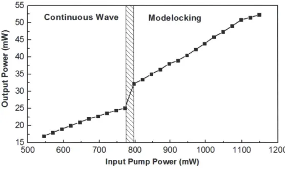
Fig. 2-5. Output power vs. input pump power. Mode-locking self-starts as the input pump power exceeds 800 mW.
The dependence of output power on the input pump power is illustrated in Fig. 2-5 for different operation regimes. At relatively low pump power, the oscillator operates at continuous
Modelocking e 0 0 '---U I-.--. Wave I I I X0
wave (CW) mode. Mode-locking self-starts as the pump power reaches -800 mW. With increasing
pump power from 800 mW to 1.15 W, the modelocked output power grows accordingly from
32 mW to 53 mW.
We characterized the laser at 1073-mW input pump power, corresponding to a laser power
of 49 mW. The measured optical spectrum, shown in Fig. 2-6(a), has 5.5-nm bandwidth at full
width at half maximum (FWHM). The RF spectrum recorded in Fig. 2-6(b) indicates a 3-GHz
repetition rate with signal to background ratio >60 dB. The output pulse duration is also measured
by a background free autocorrelator; the resulting autocorrelation trace plotted in Fig. 2-7(a) shows
a 319-fs FWHM duration (black line). As a comparison, the autocorrelation trace of the transform
limited pulse calculated from the optical spectrum in Fig. 2-6(a) is plotted in Fig. 2-7(a) as the red
dashed line. With a de-convolution factor of 1.54 (assuming a hyperbolic secant pulse profile),
the pulse duration is estimated to be -206 fs. It is about 56-fs longer than the calculated
transform-limited duration shown in Fig. 2-7(b) (i.e. 150 fs), showing that the optical pulses are
slightly chirped. . -20
a)
(b) I-0 0L 0.8 4 041 0.6-60
0.4--80 0.2 -100 0 1.005 1.015 1.025 1.035 1.045 3.008 3.0085Wavelength (urn) RF Frequency (GHz)
Fig. 2-6. (a) Optical spectrum of the output pulse with 1073-mW pump power.
(b) The RF spectrum with a resolution bandwidth of 3 kHz.
Without any enclosure of the laser or any other means to prevent ambient disturbances
(e.g., air current, vibration, temperature fluctuation, etc.), we measured the relative intensity noise
(RIN) of the 3-GHz laser running at the input pump power of 1073 mW. It is shown as the blue
curve in Fig. 2-8. Also plotted in the same figure (green dashed curve) is the integrated RIN.
Integration between 10 Hz to 10 MHz results in an integrated RIN of 0.14%.
(a)
(b)
0.8 0.8 7 0.6- 0.6-0 0 0.4 0.4- -0.2 0.2r--000-750 -500 -250 0 250 500 750 1000 -,woo -500 0 500 1000 Time (fs) Time (fs)Fig. 2-7. (a) The measured autocorrelation trace of the output pulse (black line) and the calculated autocorrelation trace of the transform-limited pulse
(red dashed line). (b) The transform limited pulse.
1E-9 0.150 1E--.0 - 0.125 E 1E-10 -1E.-11 0.075V N -E-12 L 1E-13 . 1E-14... - ' ' 0.000 id 102 id 10' 1d 12 1d Frequency (Hz)
Fig. 2-8. Relative intensity noise (RIN) (blue curve) of the mode-locked
Without any polarizing element in the cavity, the output pulses might exhibit polarization
evolution or the laser might emit stable elliptically polarized-solitons, called polarization-locked
vector solitons (PLVS's) [45-51] due to the slight birefringence in the fiber. To produce the
linearly polarized output pulses, we insert a thin-film Polarcor polarizer (0.5 mm thick) between
two aspheric lenses in the cavity.
2.5. Summary
Fig. 2-9. The photo of the third 3-GHz Yb-fiber oscillator setup built in 49D in Center
for Free-Electron Laser Science, DESY, Germany in January 2014.
We have demonstrated a fundamentally mode-locked, femtosecond (-206 fs) Yb-fiber laser with, to the best of our knowledge, the highest repetition rate of 3 GHz among reported femtosecond Yb-fiber lasers. With a 1-cm heavily Yb-doped phosphate glass fiber as the gain medium and a high-dispersion output coupler for dispersion compensation, the laser self-starts and produces up to 53-mW average power. The mode-locking usually lasts for about three days to one
week until the focusing spot on the SBR is damaged. Shifting to a different spot immediately
recovers the mode-locking. Use of a back-thinned SBR facilitates heat dissipation and helps
prevent thermal damage. With this method, the modelocking can last for more than 30 days. The
current intra-cavity loss is estimated to be ~50%, which allows us using an output coupler with
larger output coupling ratio (e.g., 10%) to increase the output power (and thus the power efficiency)
of the laser without losing the mode-locking. We have built three 3 GHz Yb-fiber oscillators in
total. Figure 2-9 shows the photo of the third 3-GHz Yb-fiber oscillator setup built in the Center
for Free-Electron Laser Science, DESY, Germany in January 2014. Ongoing work includes further
repetition rate scaling up to 10 GHz by directly sandwiching the 1-cm Yb-fiber between the output
Chapter 3
Optimization of Femtosecond Nonlinear
Yb-Fiber Amplifiers based on a
Narrowband Oscillator
3.1. Motivation
Yb-doped fiber amplifiers (YDFAs) feature superior power scalability, large single-pass gain
(~30 dB), high electrical-to-optical conversion efficiency, excellent beam quality, as well as
compactness and robustness. To avoid detrimental effects from fiber nonlinearities (e.g., self-phase
modulation (SPM), stimulated Raman scattering etc.) when amplifying ultrashort pulses, YDFAs
normally operate in a low-nonlinearity regime using chirped pulse amplification (CPA) [52,53],
in which the spectral bandwidth of the amplified pulse only changes slightly during the
amplification.
For some applications, strong nonlinear effects are preferred in YDFAs such that the
amplified pulse acquires substantial extra bandwidth, and therefore can be compressed to be much
shorter than the pulse prior to the amplification. This operation regime is of particular importance
for implementing high repetition-rate (>1 GHz) master-oscillator-power-amplification (MOPA)
systems with applications including optical arbitrary waveform generation, high-resolution
astronomical spectrographs to search for earth-like extra-solar planets [7], to name a few. The ideal
front-end of such a MOPA laser system is a fundamentally mode-locked fiber oscillator with
multi-GHz repetition rate. Primarily limited by the available pump power (~IW) from single-mode
laser diodes and low intra-cavity pulse energy, these multi-GHz fiber oscillators typically produce
sub-picosecond/picosecond pulses with <100 mW average power. The poor performance on pulse
duration and average power prevents multi-GHz fiber oscillators from most nonlinear optical
applications that usually demand femtosecond (~100 fs) pulses of several nano-joules for pulse
energy. Such a limitation can be overcome by nonlinear amplification in YDFAs which broadens
the input pulse spectrum. The spectrally-broadened, power amplified pulses are then de-chirped
by a subsequent optical compressor to much shorter pulse duration. However, relatively narrow
gain bandwidth (~40 nm) of Yb-doped fibers and the gain narrowing effect during the power
amplification usually generate compressed pulses >100-fs with considerable pedestal. In this
chapter we both numerically and experimentally study the dependence of the compressed pulse
quality on the parameters of the fiber amplifier (e.g., doping concentration and length of the gain
fiber) and the input pulse (e.g., pre-chirp, duration, and power) from the fiber oscillator. The results
from detailed numerical modeling are presented in Section 3.2 and 3.3. We find that the input pulse
pre-chirp-a quantity that can be easily tuned in experiments-is critical for optimizing the system
to achieve high-quality compressed pulses. Section 3.4 presents the experimental results
confirming the existence of an optimum negative pre-chirp that leads to the best-quality
compressed pulses, as predicted by numerical modeling. Finally Section 3.5 concludes the chapter.
3.2. Modeling Nonlinear Amplification of Femtosecond Pulses in YDFAs
Amplification of femtosecond pulses in an YDFA involves nonlinear interaction among the
modeled by coupling two sets of eqs. [54-56]: (1) the steady-state propagation rate eqs. that treat
the Yb-fiber as a two-level system and (2) the generalized nonlinear Schr6dinger equation
(GNLSE) that describes the evolution of the amplified pulses. Such a model, with all the modeling
parameters experimentally determined, enables us to study and therefore optimize a femtosecond
MOPA system.
The YDFA can be pumped in the co-propagating scheme (i.e., pump and signal propagate
in the same direction.), counter-propagating scheme (i.e., pump and seed propagate in the opposite
direction.), or both. In this chapter, we focus on the co-propagating pumping scheme which is
normally adopted in monolithic femtosecond nonlinear fiber amplifiers. Under this scenario and
with amplified spontaneous emission (ASE) neglected, the model includes the following
steady-state-propagation rate eqs. [57-59] and the GNLSE [60]:
aN
2 (tZ) = [R12 (A, z)+ W12(A,
z)]N,(t,
z) -[R 21 (A, z)+ W21 (A, z)+1 / r 21]N 2 (t, z)
at
aN, (t, z)
at = [R21 (", Z) + W21 (A, Z) +1 / T21]N2 (t, z) -[R12 (A, Z) + W2 (A, z)] N, (t, z)
P (,z) , (
az =, (A) [a, (A)N2(z) - u(A) N1 (z)]pPp (A, z) a ( =,Z) F, (A)[a, (A)N2 (z) - ua (A)N, (z)]pP (A, z).
az
a= g(')A()e dco - 8 i A+fl aA
az f 0 2 aT2 6
aT3
i a 12(2
+iy(1 + --- )(A(z,T) R(t'))A(z,T -t') dt')
wo aT fo
In Eq. (1), the amplifier is treated as a homogeneously broadened two-level system.
p accounts for the ion density per unit volume. N2 and N,, satisfying N2(tz)+N(t,z)=1, denote the
ion fraction for the upper state and the ground state. P,(,z)and P, (2,z) represent the signal and
between the pump (signal) mode and the ion distribution [61]. ae and a, denote the emission and
absorption cross-sections. The spontaneous decay rate from level 2 to 1 is ]/T21; T21 is the
characteristic fluorescence lifetime. The stimulated absorption/emission rate and pumping rate for
a fiber core-area A are Wy=T1s()aeaPs/hvsA and Ry=TFp(A)ae,aPp/hvpA, respectively. For the steady-state solution, by setting aN2(t,z)/at =0 , we then obtain N2(z) =[R12(A,z) + W12(A,,z)]/[R]2(A,z) +R21(A,z) + W12(A,z) + W21(A,z) + /T21]. (3) When writing Eq. (3), we assume that the inverse of the pulse's repetition-rate is much shorter
than the relaxation time of the upper level (~I ms), which holds for our devices.
The nonlinear propagation of the signal pulse is governed by the standard GNLSE
(i.e., Eq. (2)), taking into account the gain, dispersion, self-phase modulation, self-steepening, and
stimulated Raman scattering. A(z,t),
pn,
y, and Wo are the amplitude of the slowly varying envelopeof the pulse, n-th order fiber dispersion, fiber nonlinearity, and central frequency of the pulse,
respectively. R(t) denotes both the instantaneous electronic and delayed molecular responses of
silica molecules, and is defined as R(t)=(1-fR3(t) + fR(ri2 + T22)/(TiT22)exp(-t/T2)sin(tTJ) where
fR, ri, and T2 are 0.18, 12.2 fs, and 32 fs, respectively [60]. The GNLSE is solved by the split-step Fourier method implemented using the fourth-order Runge-Kutta method in the interaction
picture [62] with adaptive step-size control [63].
Rate___________
A(o z) -- P,:(o, z.)
>
Equation P S(o, 4+Az). A(o, zo+Az)
<-FGNLE
-
g(o), Z0) = 1/(2 Az) log [PS(O, z0+Az)P(o, z0)
Flow chart in Fig. 3-1 illustrates the iteration in numerically solving Eq. (1) and (2). In each step, the signal power spectrum Ps(w,zo) is first calculated from A(w,zo) and then substituted into the rate equation Eq. (1) to obtain the signal power Ps(o),zo+Az) at the next position. The gain spectrum g(w,zo) is derived from Ps(o , zo+Az) and Ps(w,zo), and fed into Eq. (2) to derive
A(6o, zol+Az) from A(w,zo). Repeating this iteration generates the longitudinal distribution of pump power and population inversion as well as the nonlinear evolution of the seed-pulse along the gain fiber.
Table 3-1. Amplifier parameters used in the simulation
Core Core Fluorescence
Pump Diameter Numerical
Lifetime fl2 f.3 y Wavelength () Aperture
K
(a) (N.A.) 976 nm 5 m 0.13 1.4 ms 23 30 0.0047 fs2/mm fs3/mm (Wm)Table 3-1 lists the key simulation parameters. For a single-mode step-index fiber with its fundamental mode approximated by a Gaussian, the overlap of the optical mode and ion distribution becomes F=-exp(-2a2 2
). a is the ion dopant radius or core radius and w the mode field radius at l/e2
power intensity approximated by the Whitely model: w=a(O. 616+1.66/ V'.5
+0.987/) [41], where V is the normalized frequency. The wavelength dependent emission cross-section ue and absorption cross-sections ua are adapted from Fig. 2 in Ref. 30.


![[PDF] Cours de base d’introduction au logiciel Ciel Gestion Commerciale | Cours informatique](data:image/gif;base64,R0lGODlhAQABAIAAAP///wAAACH5BAEAAAAALAAAAAABAAEAAAICRAEAOw==)