Biogas robust processing with combined
catalytic reformer and trap:
BioRobur Project
Y. S. Montenegro Camacho
1, S. Bensaid
1, D. Fino
1, D. Trimis
2,
A. Herrmann
2, N. Guilhaume
3, Y. Schuurman
3,
A. G. Konsatndopoulos
4, S. Lorentzou
4, S. Gianella
5, M. Antonini
6,
L. Marchisio
6, A. Ortona
7& A. Khinsky
8 1Politecnico di Torino, DISAT, Torino, Italy 2TU Bergakademie Freiberg, ITE, Germany 3Université Lyon 1, IRCE, France4APT, CERTH-CPERI, Greece 5Erbicol, Switzerland
6Hysytech, Italy
7ICIMSI-SUPSI, Switzerland 8Amiagus, Lithuania
Abstract
The present work summarizes experimental results obtained up to a lab scale level within the framework of the SP1-JTI-FCH.2-Collaborative Project ‘BIOROBUR’. The main objective of the project is the development and testing of a robust and efficient fuel processor based on direct autothermal reforming (ATR) of biogas, and demonstration at a scale equivalent of 50 Nm3/h hydrogen production. Modelling and simulation (CFD and FEM) were carried out to select the catalyst support with promising results for the BioRobur fuel processor and, furthermore, 2D CFD analysis also were used to examine flow uniformity issues due to soot trap integration provided immediately downstream the reformer. Catalysts for the ATR reformer and soot trap were synthesized and tested. The results achieved so far are highly promising. Besides, safety studies and life cycle analysis (LCA) of the overall process are also being conducted. The partners involved in the
BioRobur project bring together a sufficient number of important European actors on a scientific, research and industry level.
Keywords: robust and efficient fuel processor, biogas, hydrogen, ATR reformer, catalysts, soot trap, gasification, modelling, simulation, catalyst support.
1 Introduction
Hydrogen produced from renewable sources, such as biogas; looks like a highly promising energy carrier in the near future in a new sustainable energetic scenario of reduced emissions. Within this context, the integration of biogas reforming processes and the activation of fuel cell using H2 represent an important way for generating clean energy, with added high-energy efficiency [1, 2].
The project is focused on hydrogen production by direct biogas reforming (not from purified biomethane), with no preliminary CO2 separation, aimed at covering a wide span of potential applications, from fuel cells feed (both high temperature SOFC or MCFC fuel cells and low temperature PEM ones, requiring a significantly lower inlet CO concentration) up to the production of pure, PEM-grade hydrogen. To reform this gas stream identifying suitable catalytic systems is needed, so to that over time lower susceptibility to degradation due to carbonaceous material fouling or sulphur poisoning is achieved. In addition to enhanced catalytic and reactor systems, improvement of control strategies are needed for independent and robust operation. The control strategies should ensure the operation independent of feedstock composition variations in time. The control strategies and processes layout should avoid carbon deposition formation. To avoid particulate emissions leading to environmental problems as well as the need to prevent an undesirable deposition on the catalysts of the fuel cell, contributing a fast degradation of the component, a wall-flow soot trap has been placed downstream the reformer to retain most of the soot produced by the reactor [3]. The nominal production rate of pure hydrogen of the BioRobur fuel processor will be 50 Nm3/h with an overall efficiency of the conversion of biogas to green hydrogen of 65%.
2 Optimization of the process efficiency
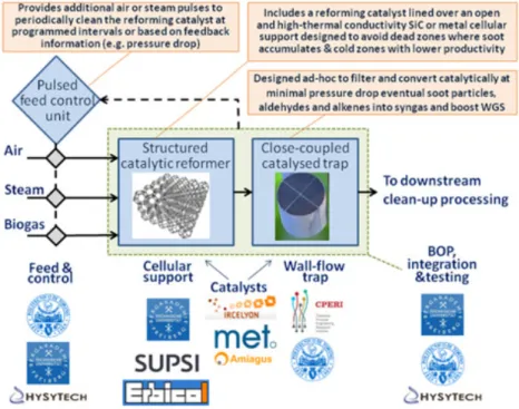
The concept and its key features are schematically represented in Figure 1, where the main roles of the eight partners involved are also defined. The overall originality of the project is the use of structured catalyst for the ATR reaction, which is based on high thermal conductivity cellular materials to disperse the heat axially in the reactor, and the adoption of a novel approach to retain particulate matter emissions in a catalytic wall-flow trap based on transition metal catalysts, downstream from a biogas ATR, which could entail effective filtration and gasification of soot particles eventually generated in the inlet part of the reformer during steady or transient operation, or due to the decomposition of traces of incomplete reforming products [4]. The main scope of work comprises research and technological development activities on materials, catalysts and processes for
Figure 1: Scheme of the BioRobur reformer core innovations and partners’ roles.
chemical conversion, as well as their integration and prototyping in an efficient, thermally optimized system.
Figure 2 shows an overview of the project. As is possible to see, the overall system is split up into three main sections, the first process step is composed by compression, pre-heating and mixing of air, steam and biogas. After the mixing of steam with air biogas is supported by a steam ejector, which operates with the superheated steam-air mixture. The second process step is made up of the catalytic conversion of the mixture to syngas (H2- and CO-rich mixture) in the ATR unit close coupled to a wall flow filter to retain the soot produced. The third section consists in the gas purification with high-temperature (HT-WGS) and low-temperature water gas shift (LT-WGS) reactors as well as a downstream pressure swing adsorption (PSA) unit. The last section will be not realized within BioRobur project due to the huge availability of equipment for syngas purification, however, it is considered for process optimization and fuel processor efficiency calculations. Instead of, a flare will be located after the soot trap to burn the syngas produced in the process. In order to design the BioRobur processor, heat and mass balance for the overall system has been generated using Aspen simulation. The efficiency of the process depends on the biogas reforming route (catalytic partial oxidation, steam reforming or autothermal reforming), the level of heat integration, the preheating temperature of the mixed reactants, the steam-to-carbon (S/C) and
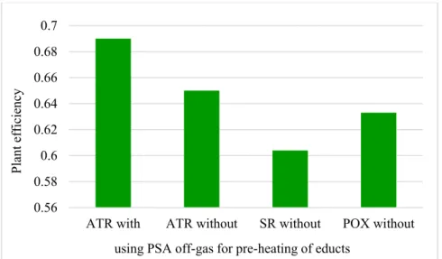
oxygen-to-carbon (O/C) ratio as well as the usage of the off-gas from pressure swing adsorption (PSA). The results (Figure 3) show that the highest efficiency equal to 65% (using S/C=1.5 and O/C=1.02) is achieved with an ATR. Furthermore, other advantages of ATR concern the presence of water, which increases hydrogen yield and reduces the soot production, the speed with which the reactor can be stopped and restarted, and the capacity to produce higher amounts of H2 with lower O2 consumption [1].
Figure 2: Block flow diagram of BioRobur process (without heat integration).
Figure 3: Maximum plant efficiency for different process types of biogas reforming with maximum heat integration.
0.56 0.58 0.6 0.62 0.64 0.66 0.68 0.7
ATR with ATR without SR without POX without
Plant efficiency
Through the energetic usage of the PSA off-gas for steam generation and superheating, a system efficiency up to nearly 70% is realizable, due to higher hydrogen yields in the synthetic gas resulting from an enhanced S/C ratio [5].
3 Experimental condition and first results
3.1 Simulation of the structured catalyst supports to ATR reactor
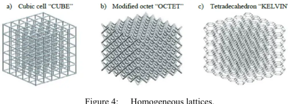
In order to identify a suitable support structure, which meets the desired demands, i.e. high effective thermal conductivity, open structure to avoid dead zones and plugging by soot build up, strong mixing and high contact time of the fluid with the catalytic surface, high mechanical strength and low pressure drop; numerical simulations of fluid flow, heat transfer and mechanical behavior numerical simulations based on CFD and FEM models have been performed on three different geometries (Figure 4) which are assessed by different effective properties. While conventional catalyst supports like honeycombs and solid bulk material suffer from certain shortcomings such as poor transverse mixing in case of honeycombs or high pressure loss and poor heat transfer in case of packed beds [6], the 3D printing method employed in the BioRobur project offers the opportunity to produce almost arbitrary designs of catalyst supports.
Figure 4: Homogeneous lattices.
In order to obtain the isothermal transient flow field, the governing equations for mass and momentum are numerically solved using a CFD code based on the Lattice-Boltzmann method (LBM).
For evaluating the effective thermal conductivity of the structures, the heat transfer was solved by using the finite volume method (FVM) under the assumption of a non-conducting fluid phase.
To test the mechanical behavior of the supports made of SiSiC lattice structures, an analysis on the basis of the finite element method (FEM) was performed employing the commercial software COMSOL V4.4. For generation of the lattice structures each strut has been modeled by two vertices and a connection between them using MATLAB.
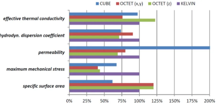
The results suggest a lattice composed of Kelvin cells as the most suitable catalyst support structure. The Kelvin cell structure features the highest turbulent kinetic energy over the entire range of Reynolds numbers at a moderate pressure
loss if compared to the modified octet cell. Furthermore, the Kelvin cells are characterized by a high effective thermal conductivity in all directions as well as a relatively high specific surface area. Although the Kelvin cell is mechanically weaker than the other two cell types, it is expected that it can handle the loads exerted on the support structure [5].
3.2 ATR catalysts
Different catalysts were synthesized and tested along with some commercial catalysts in order to select the most appropriate for the BioRobur context. The catalysts must guarantee some important features such as less prone to coking and easier adaptability to the change of biogas composition. Nickel supported on mixed oxides, perovskites and spinels were synthesized for the ATR reaction and tested in a six parallel-flow reactor technology implemented to test simultaneously six different catalysts under a feed consisting of 42% H2O, 14% CH4, 9% CO2, 7% O2 in argon. Table 1 lists the nine catalysts screened for the reforming of biogas with the nickel loading, surface area and nickel dispersion of the tested catalysts. Tests were performed with quartz reactors at 700°C (oven setpoint) under atmospheric pressure. Reactors had a length of 180 mm and an inner diameter of 4 mm. Catalyst beds were composed of 20 mg of prepared catalyst diluted with quartz powder [7].
The biogas reforming take a place by the reaction (1):
CH ½xO yCO 1 x y H O ↔ y 1 CO 3 x y H (1) 5-0.05 wt.% Ni-Rh/ MgAl2O4 catalyst showed full methane conversion over 200 hours with a constant hydrogen production (as shown in Figure 5). The deactivation process of the catalyst could be related to some carbon deposition, but the main fast final deactivation process is likely associated to nickel oxidation. From the results id possible to conclude that the Rh promotes Ni stability.
Figure 5: Summary of the detailed numerical simulations on the catalyst support structures. Results are displayed normalized with respect to the results of Kelvin cell.
Table 1: Ni loading, surface area and Ni dispersion on prepared catalysts.
The results of catalyst screening are shown in Figure 6.
Figure 6: Methane conversion (left) and Hydrogen production (right) (μmol/min) from biogas with 60% of CH4 and 40% of CO2 at T=700°C with S/C=3, O/C=0.5.
3.3 Characterization and integration of the wall-flow catalyst trap into the ATR reactor
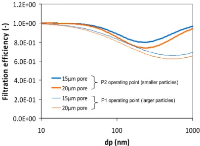
The monolithic samples (15 and 20 mean μm pore size, 46% porosity) that were acquired from CTI (Céramiques Techniques Industrielles) filter manufacturer were used to evaluate their performance with respect to i) their flow resistance (permeability), ii) filtration efficiency and iii) development of pressure drop during loading of carbonaceous materials generated from a CAST burner, and iv) the ability of regeneration of the lab-scale un catalyzed samples. Two operating points were employed during the filtration efficiency measurement experiments with the CAST. The one point (P2) corresponded to smaller particle mean size and the second point (P1) to larger particles.
The results showed that both monoliths develop similar pressure drop as a function of the filtration velocity, both filter materials filter the smaller particles more effectively and in both cases the filtration efficiency quickly increases to reach 99% as soot particles accumulate on the monoliths (Figure 7).
Figure 7: Filtration efficiency as a function of soot particle size, of CTI1 and CTI2 monoliths at two different operating points.
Figure 8: Soot oxidation rate curves as a function of temperature for the two different monoliths loaded with particles produced at the two different CAST operating points (P1 and P2).
Typical soot oxidation rate curves as a function of temperature are depicted in Figure 8. It can be observed that the monoliths loaded with the smaller particles
0.0E+00 2.0E‐01 4.0E‐01 6.0E‐01 8.0E‐01 1.0E+00 1.2E+00 10 100 1000 dp (nm) Filtra ti o n ef fi ci en cy ( ‐) 15μm pore 20μm pore 15μm pore 20μm pore
P2 operating point (smaller particles) P1 operating point (larger particles)
(P2 operating point) are more easily oxidized than the larger particles, probably due to higher exposed surface area of the deposited particles as well as to a more amorphous and easily oxidizable structure of the primary particles produced at that operating point.
To conclude this part, although the monolith with the smaller mean pore size has a slightly better performance with respect to filtration efficiency and pressure drop development during soot loading it can be deduced that the difference in the pore size is not so great and will not cause any significant differences in the performance of the two filters.
In the study related to the particle trap integration, a 2D CFD analysis with the ANSYS Fluent 15.0 software is conducted in order to examine flow uniformity issues due to the soot trap placement. The soot trap integration focused on: a) the degree of flow uniformity required in the heat exchanger, since the trap displaces the originally present flow distributor plates, b) the stagnant flow space around the trap; c) mechanical fixation of the trap including rings and flanges, d) whether there is the need to secure the trap axially, and e) the requirement for being able to install and remove the trap from the top access of the ATR. The trap monolith dimensions and placement determine the space available for including such a distributor plate. The CFD calculation results must essentially confirm that the selected particle trap dimensions and position are acceptable in that they permit, with acceptable cost in pressure drop, the provision of uniform flow entry into the heat exchanger. It is found that a distributor plate is necessary for acceptable flow pattern into the heat exchanger tubes. Satisfactory flow distribution can be obtained with relatively small pressure drop penalty (< 0.5 mbar), achievable in practice with a perforate plate of < 1 mm hole diameter and ≈19% open area. 3.4 Catalyst for the soot trap
The syngas produced by ATR reforming is constituted by carbon dioxide (CO2), carbon monoxide (CO), hydrogen (H2) and steam (H2O). The possibility to gasify soot in this specific environment can be reached according to the following reactions for the carbon [8]:
C H O → CO H ∆H° 131.4 kJ/mol (2)
C CO → 2CO ∆H° 172 kJ/mol (3)
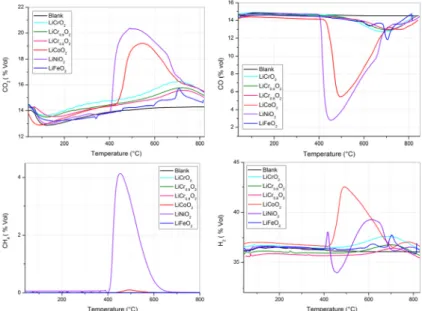
Li-delafossite based catalysts were prepared via a solution combustion synthesis (SCS) method and investigated under realistic conditions as catalysts for the gasification of particulate matter retained in a soot trap downstream from a biogas autothermal reformer (ATR). The LiFeO2 and LiCoO2 catalyst exhibited the highest activity toward the catalytic gasification of soot in a synthesis gas mixture (Figure 9).
The activity of the catalysts towards soot gasification was analyzed by temperature programmed reaction (TPRe), which was carried out in a fixed-bed micro-reactor. A flow of 100 ml/min of CO2 (10.92%), CO (10.6%), H2 (26.83%),
4 Conclusion and outlook
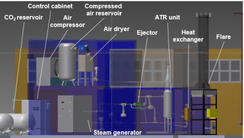
In this paper regarding the technical development in the Biogas robust processing, the project has made significant progress toward meeting its objectives. The results obtained are very promising. All major system components have been developed and are being completely characterised for single component operation mode. They will be integrated into a first prototype complete system for a pilot plant. The BioRobur plant will be tested at a scale of nearly 50 Nm³/h hydrogen generation in order to demonstrate the feasibility of producing renewable hydrogen from biogas. The 3D layout of the system is shown in Figure 10.
H2O (24.87%) and N2 (26.76%) was sent to a fixed bed of 50 mg of a mixture of carbon (Printex U) and powdered catalyst (ratio 1:9 on a mass basis) with 150 mg of inert silica (to reduce the specific pressure drop and to prevent thermal runaways). The results obtained are very promising, showing relatively fast gasification of soot. LiFeO2 and LiCoO2 present the best performance to gasification of carbon. The 98% and 99% of soot is gasified before 850°C when LiCoO2 and LiFeO2 were used as catalysts while approximately the 50% is just gasified without catalyst before 850°C. The same encouraging results were also obtained at structured level where the activities of the catalysts were almost retained.
Figure 9: Results of catalytic activity of all prepared delafossite catalysts. % Vol CO (Up-right), % Vol CO2 (Up-left), % Vol CH4 (bottom-right) and % Vol H2 (bottom-left) vs. Temperature (°C).
Figure 10: Rendering of the BioRobur pilot plant.
Acknowledgement
The authors would like to thank the European commission for the financial support of this work in the Seventh Framework Programme project BioRobur under grant agreement n° 325383.
References
[1] Alves, H.J., Junior, C.B., Niklevicz, R.R., Frigo, E.P., Frigo, M.S. & Coimbra-Araujo, C.H., Overview of hydrogen production technologies from biogas and the applications in fuel cells. International Journal of Hydrogen
Energy, 38 (13), pp. 5215–5225, 2013.
[2] Bensaid, S., Russo, N. & Fino, D., Power and Hydrogen Co-generation from Biogas. Energy Fuels, 24(9), pp. 4743–4747, 2010.
[3] Raimondi, A., Fino, D. & Saracco, G., New concept for soot removal from a syngas mixture. Journal of Power Sources, 193(1), pp. 338–341, 2009. [4] Parizotto, N.V.. Rocha, K.O., Damyanova, S., Passos, F.B., Zanchet, D.,
Marques, C.M.P. & Bueno, J.M.C., Alumina-supported Ni catalysts modified with silver for the steam reforming of methane: Effect of Ag on the control of coke formation. Applied Catalysis A: General, 330 (10), pp. 12–22, 2007. [5] Herrmann, A., Pönisch, M., Werzner, E., Laurinat, M., Rezaei, E., Ortona, A.,
Bensaid, S., Fino D. &Trimis, D., Development of an Autothermal Biogas Processor for Hydrogen Production. Proc. of the International Gas Union Research Conference (IGRC 2014). Copenhagen, Denmark, September 17-19, 2014, pp. 1257–1267.
[6] Ortona, A., D’Angelo, C., Gianella, S. & Gaia, D., Cellular ceramics produced by rapid prototyping and replicatio. Materials Letters, 80(1), pp. 95–98, 2012.
[7] Luneau, M., Guilhaume, N., Meunier, F. & Schuurman, Y., Six-flow reactor technology applied to catalyst screening for the autothermal reforming of model bioga, 3rd International Symposium on Green Chemistry, La Rochelle,
France, 2015.
[8] Raimondi, A., Loukou, A., Fino, D. & Trimis, D., Experimental analysis of soot abatement in reducing syngas for high temperature fuel cell feeding,
Chemical Engineering Journal , 176– 177(1), pp. 295–301, 2011.